December 17, 2020 Lada.Online 18 343 19
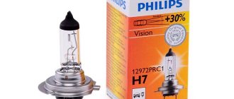
Good halogen car lamps can cost more than 1 thousand rubles. It will be a shame if they quickly burn out. To extend their service life, it is enough to implement their smooth ignition. After all, incandescent lamps most often burn out the moment they are turned on. You can modify the design yourself in two different ways.
Smooth switching on of LEDs with your own hands
Do-it-yourself smooth switching on and dimming of LEDs
I think everyone understands what smooth switching is, or otherwise the ignition of LEDs.
Let us examine in detail the smooth switching on of LEDs with our own hands.
The LEDs should not light up immediately, but after 3-4 seconds, but initially not blink or light up at all.
Device diagram:
Components:
■ Transistor IRF9540N ■ Transistor KT503 ■ Rectifier diode 1N4148 ■ Capacitor 25V100µF ■ Resistors: - R1: 4.7 kOhm 0.25 W - R2: 68 kOhm 0.25 W - R3: 51 kOhm 0.25 W - R4: 10 kOhm 0.25 W ■ Single-sided fiberglass and ferric chloride ■ Screw terminal blocks, 2 and 3 pins, 5 mm
You can change the ignition and decay time of the LEDs by selecting the value of resistance R2, as well as selecting the capacitance of the capacitor.
Using a utility knife, I made grooves along the marked lines, then sawed them out with a hacksaw and sharpened the edges with a file. I also tried using metal scissors - it turned out to be much easier, more convenient and dust-free.
Next, sand the workpiece under water with P800-1000 grit sandpaper. Then we dry and degrease the surface of the board with 646 solvent using a lint-free cloth. After this, it is not advisable to touch the surface of the board with your hands.
Next, using the SprintLayot program, open and print the diagram on a laser printer. You only need to print the layer with tracks without markings.
To do this, when printing in the program, at the top left in the “layers” section, uncheck unnecessary boxes. Also, when printing, in the printer settings we set high definition and maximum image quality.
Using masking tape, glue a glossy magazine page/glossy photo paper (if their size is smaller than A4) onto a regular A4 sheet and print our diagram on it. I tried using tracing paper, glossy magazine pages and photo paper.
Now we warm up the textolite and attach our printout. Then use an iron with good pressure to iron the board for several minutes.
Now let the board cool completely, then put it in a container of cold water for a few minutes and carefully remove the paper from the board. If it doesn’t come off completely, then roll it up slowly with your fingers.
Then we check the quality of the printed tracks, and touch up the bad places with a thin permanent marker.
The etching time depends on many parameters, so we periodically remove and check our board. We use anhydrous ferric chloride, dilute it in warm water according to the proportions indicated on the package.
To speed up the etching process, you can periodically shake the container with the solution.
After the unnecessary copper has been removed, we wash the board in water. Then, using a solvent or sandpaper, remove the toner from the tracks.
Next you need to tin the board. There are many different ways, I decided to use one of the simplest and most accessible. Using a brush, we lubricate the board with flux (for example LTI-120) and tin the tracks with a soldering iron. The main thing is not to keep the soldering iron tip in one place, otherwise the tracks may come off due to overheating. We take more solder onto the tip and move it along the path.
Now we solder the necessary elements according to the diagram. For convenience, in SprintLayot I printed out a diagram with symbols on plain paper and, when soldering, checked the correct arrangement of the elements.
After soldering, it is very important to completely wash off the flux, otherwise there may be shorts between the conductors (depending on the flux used). First, I recommend thoroughly wiping the board with 646 solvent, and then rinsing it well with a brush and soap and drying it
Result:
Protection block "Granit BZ"
The UPVL Granit soft-start device effectively performs protective functions against destructive current surges when connected to a load. The block stabilizes the supply voltage, which now does not depend on the overvoltage in the network and allows you to increase the operating time of the lamps by 4-6 times. The device provides real cost savings and reduces consumer costs for lighting.
Operating parameters of the block:
- mains voltage up to 240 V;
- maximum load up to 230 V;
- operating temperature -15 oC… +35 oC;
- "Granit BZ" is connected in series with 220 V lamps.
Operating principle
To ensure a uniform increase in the applied voltage, it is enough for the phase angle to increase in just a few seconds. The current surge is smoothed out, and the coils gradually heat up. The figure below shows one of the simplest protective circuits.
Scheme of a device for protecting against burnout of halogen and incandescent lamps on a thyristor
When turned on, the negative half-wave is supplied to the lamp through a diode (VD2), the power supply is only half the voltage. During the positive half-cycle, the capacitor (C1) is charged. When the voltage across it rises to the opening value of the thyristor (VS1), the lamp is fully supplied with mains voltage, and the start-up ends with full glow.
Diagram of a lamp burnout protection device using a triac
The circuit in the figure above operates on a triac that allows current to pass in both directions. When the lamp is turned on, negative current passes through the diode (VD1) and resistor (R1) to the control electrode of the triac. It opens and skips one half of the half-cycles. Within a few seconds, the capacitor (C1) is charged, after which the positive half-cycles open, and the lamp is fully supplied with mains voltage.
The device on the KR1182PM1 microcircuit allows you to start the lamp with a smooth increase in voltage from 5 V to 220 V.
Device diagram: starting incandescent or halogen lamps with phase control
The microcircuit (DA1) consists of two thyristors. The decoupling between the power part and the control circuit is made by a triac (VS1). The voltage in the control circuit does not exceed 12 V. The signal is supplied to its control electrode from pin 1 of the phase regulator (DA1) through a resistor (R1). The circuit starts when the contacts (SA1) open. In this case, the capacitor (C3) begins to charge. The microcircuit starts working from it, increasing the current passing to the control electrode of the triac. It begins to gradually open, increasing the voltage on the incandescent lamp (EL1). The time delay for its ignition is determined by the capacitance value of the capacitor (C3). It should not be made too large, since with frequent switching the circuit will not have time to prepare for a new start.
When you manually close the contacts (SA1), the capacitor begins to discharge into the resistor (R2) and the lamp turns off smoothly. Its switching time changes from 1 to 10 seconds with a corresponding change in capacitance (C3) from 47 μF to 470 μF. The lamp extinguishing time is determined by the resistance value (R2).
The circuit is protected from interference by a resistor (R4) and a capacitor (C4). The printed circuit board with all the parts is placed on the rear terminals of the switch and installed together with it in the box.
The lamp starts when the switch is turned off. A glow discharge lamp (HL1) is installed for illumination and voltage indication.
Installation location of the protective block
Smooth switching on of light in an apartment is achieved by choosing the right installation location. Protection for each lamp is installed depending on its location. If technically possible, it is better to place it in the cavity under the chandelier. The advantage of the device is its compactness. Therefore, it is installed in any accessible place next to the lighting fixture.
Detailed instructions are supplied with the unit. Therefore, you can install it yourself without resorting to the services of an electrician. If the power of the UPVL allows, installation for a group of several lamps is possible. In this case, the best placement location is a junction box. If the protective circuit contains a lighting transformer to reduce power, then the unit should be located first along the current flow. The 220 V voltage should be supplied to it first, and then along the circuit to the entire lighting network.
When installing a soft-light switching device, you must adhere to strict rules:
- Availability for repairs.
- It is forbidden to cover the UPVL with wallpaper, cover it with plasterboard and seal it with plaster.
How to smoothly switch on low and high beam headlights and what is this for? »
Drivers often ask how to smoothly switch on low and high beam headlights. This switching not only gives the car a more interesting appearance and has less impact on vision, but also increases the service life of halogen bulbs. To create this effect, it is necessary to achieve a smooth attenuation of the filament. This is a fairly common type of optics tuning.
At the same time, it does not cause any problems with traffic police officers, which is important in light of increasingly increasing fines. So, let's consider how this effect is achieved, and whether you need to spend your time on it
What gives?
How to smoothly switch on low and high beam headlights and why this is needed
. The main function of such a device is to protect the light bulb from burning out. To better understand the situation, let's consider it from the point of view of physics. Everyone knows Ohm's law, or guesses about its existence. Based on this rule, it follows that current strength is always inversely proportional to resistance. Formula I=U/R,
We probably saw everything at school. The filament of a car light bulb in a cold state has a resistance 10-12 times higher than when heated. When voltage and power are applied to it, the current also increases by the same amount. For a standard 55 W lamp, this figure can reach 60 Amperes.
True, this current strength does not last long, only until the coil warms up, after which the current strength decreases to normal levels. The light bulbs are designed for such an increase, and in theory nothing bad should happen. But everyone knows the ability of incandescent lamps to burn out when they are turned on. It's all about the uneven wear of the spiral. During operation, some areas evaporate faster for various reasons, the thinning spiral becomes more sensitive to increased current and burns out.
Smooth switching of the light does not provide maximum power from the very beginning, which prevents the current from increasing to dangerous levels. Thus, it is possible to significantly increase the service life of halogen lamps (see article “”). This is especially true for “white light” lamps, which have a shorter lifespan.
Ways to solve the problem
To eliminate the problem, it is enough to reduce the power that is dissipated during startup. To do this, it is necessary to reduce the current in this circuit. There are several ways to solve the problem:
- A fairly powerful field-effect transistor with a capacitor on the gate. The transistor initially passes a small amount of current. At the same time, its capacitor is gradually charged, opening the shutter. With a fully charged capacitor, the power goes entirely to the lamp, eliminating the need for a relay. The disadvantage of the scheme can be considered the need to remove a large amount of heat;
- with an NTS thermistor and relay
works similarly . In the case of a car, it is better to use a 2-5 ohm thermistor. It is connected in series to the lamp. At the same time, it dissipates part of the power. As the thermistor gradually heats up, it reduces its resistance. The power on the light bulb increases when this indicator reaches a certain level; a relay connected in parallel with the lamp disconnects the thermistor from the circuit, providing the lamp with maximum voltage; - Pulse width modulation
. Unlike those described above, this method does not limit the current, which reduces power dissipation. This reduces the need for cooling. The circuit uses a field effect transistor. Through it, voltage is not supplied to the light bulb constantly, but with pulses of several microseconds. Thanks to this, the coil heats up evenly. And the headlights gradually turn on.
Work algorithm
| Slow warm-up |
If the ignition was turned off, then when the headlights are turned on for the first time, a slow warm-up occurs:
— within 3 seconds, the PWM duty cycle smoothly increases to 30%;
— then, for 2 seconds, it remains at the same level, allowing the lamps to gradually increase temperature;
- then, within 3 seconds it increases to 80%, giving an acceptable level of illumination;
- and finally, within 4 seconds it is brought to 100%.
| Hold after shutdown |
When the headlights are turned off, the PWM duty cycle is immediately set to 50%, allowing the capacitor to charge.
— It is held at this level for 0.5 seconds;
- and then smoothly decreases to zero within 0.5 seconds.
If the ignition was not turned off, then when the headlights are turned on again, a rapid warm-up occurs:
— within 0.5 seconds the level increases to 80%;
- and then within 1 second it is brought to 100%.
| Quick warm-up |
If the headlights were turned off during slow warm-up, then:
— if the level has reached 50%, then the transition to the holding phase occurs.
— if the level is less than 50%, then the light turns off, and the next time the headlights are turned on will be considered the first, and a smooth warm-up will be performed.
If the headlights were turned off during rapid warm-up, then:
— if the level is greater than or equal to 50%, then the transition to the holding phase occurs
— if the level is less than 50%, then the transition to the holding phase is carried out to the position of the falling part that corresponds to the current level. In other words, there is a smooth attenuation without a half-second hold.
If the headlights were turned on again during the hold phase, a transition to the fast warm-up phase is carried out, to a point on the graph whose level corresponds to the current PWM duty cycle.
Tags: lighting, ceiling light, soft start
Comments 43
Tell me, is a bipolar transistor suitable here (KT837D)?
did you draw a signet in the sprint? if so, can you send it to me?
I'll look at it on my home computer in the evening, and if I have any left, I'll post it.
as a friendly criticism: 1. instead of a nickname, it would be better to leave a polygon for heat dissipation, and in general route the board so that there is no need to etch, but it would be possible to draw out isolated areas with a craft knife 2. do not solder the wires to the board , and connect it with a connector - when you want to improve the device, you could simply replace it
The heat dissipation is clearly unnecessary... The transistor is powerful, but the diodes in the lampshade consume just a little bit. It is higher than the ambient temperature and does not heat up. Regarding marking the board with a stationery knife - well, I don’t like this kind of collective farm. I’d rather spend an extra half an hour or an hour, but I’ll do everything beautifully. The connector is located, but not on the board itself, but on a five-centimeter piece of wire. This makes it more convenient to place the device under the ceiling - first stick it in place as it should, and then connect the wires.
and how did you etch the board? How did you apply it to the textile?
The tracks were applied using photoresist. Etched in a solution of hydrogen peroxide, salt and citric acid.
I remember, I used to paint paths with varnish... I etched them in ferric chloride))) don’t they do that anymore?))) Psst I’m behind...
Well, probably no one paints with varnish now, it’s easier to do it with the same LUT. But I myself used ferric chloride until recently, until I learned about the method with hydrogen peroxide - it’s easier to get, and cheaper, and it doesn’t stain everything around)))
and how did you etch the board? How did you apply it to the textile?
TextOlit. Actually, it’s fiberglass.
ok, that’s it, I was being clever...
If you like being illiterate, stay...
Do you often use textolite? since there was fiberglass here... I think it’s already clear what kind of material it is... there’s a mistake in the name - yes, I remember it correctly. But. I don’t think it’s a mistake to simply call the material for boards PCB. I think many people say this so as not to lengthen an already understandable word. It's like always adding a lead-acid battery to a car. I don't think you're adding either. fiberglass = textolite. the essence of what we are talking about does not change at all.
The fact is that PCB is a fabric impregnated with glue. It is brown in color. www.ru.all.biz/img/ru/catalog/2068698.jpeg It is not metallized and is not used for the production of printed circuit boards.
And fiberglass is fiberglass impregnated with epoxy resin; it is light yellow in color. And the properties of the materials are very different.
Getinax is also used as a dielectric for printed circuit boards - this is paper impregnated with glue. Also, by the way, brown.
Getinax is often used in household appliances (previously, only getinax was used). Fiberglass began to replace it a couple of decades ago.
Yes, I’ve been doing electronics for a long time, 40 years already. I designed and manufactured my first printed circuit board at the age of 12, i.e. in 1982...
Thyristor circuit
This scheme can be recommended for repetition. It consists of common elements that gather dust in attics and closets.
In the circuit of the rectifier bridge VD1, VD2, VD3, VD4 there is an incandescent lamp EL1 as a load and current limiter. The rectifier arms contain thyristor VS1 and a shifting chain R1 and R2, C1. The installation of a diode bridge is determined by the specific operation of the thyristor.
After applying voltage to the circuit, current flows through the filament and enters the rectifier bridge, then the electrolyte capacity is charged through the resistor. When the voltage reaches the opening threshold of the thyristor, it opens and passes the incandescent light bulb current through itself. This results in a gradual, smooth heating of the tungsten coil. The warm-up time depends on the capacitance of the capacitor and resistor.
Design Features
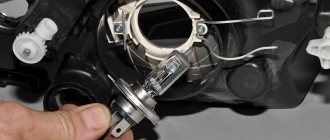
Lamps
. Cars use pod lights that combine passing and leading lights (single thread bulbs) and turn indicators. In addition, the headlights have parking light bulbs. The low and high headlight beams are activated using auxiliary relays K4 and K5 located in the mounting block. The control voltage to the relay coils is supplied from the headlight switch when the headlight switch switch is fully pressed. When the low beam is turned on, the low beam lamp comes on, and when the high
, all lamps (passage and movement) are illuminated.
turn on
in no time by pulling the light switch lever towards you.
In this case, the voltage at contact “30” of the switch is supplied directly from the power sources. In the wiring harness of wiring harness B for connecting the wires when installing headlights with low beam lamps with double hood. In this case, the gray wire with a red stripe in connector B must be connected to the same color wire as the switch's "56b" connector. Then, when the low
, the low beam bulb in the double brake lamps comes on, and when the high beam beam is switched on, the high beam bulbs in the double brake lamps and the headlight come on.
Fog lights
. On VAZ 2110 vehicles, in the optional version, fog lights can be installed on the front bumpers. The headlights are switched on by switch 27 (see Instrument panel) using an additional relay type 113.3747 installed in a shoe attached to the rear side of the mounting block. The fog lights can only be turned on if the exterior light
26.
Accelerated self-training course for novice drivers: Sign up for lessons.
https://youtube.com/watch?v=6XsMfAPBhtw
HOW TO CONNECT AUTOMATIC LOW BEAM
, THERE IS CONTROL OF LIGHT OPERATION AND.
Outdoor Lighting
. The ambient light is turned on by the external lighting switch 26 (in positions “I” and “II”). The parking light and brake light lamps are supplied via lamp control relay K1. If any lamp is on, the relay is activated by the corresponding LED indicator in block 5 (see Instrument panel) of the on-board monitoring system.
Direction indicators
. The direction indicators for the starboard or port side are activated using the switch lever. In emergency mode, switch 42 turns on all direction indicators. The flashing of the lamps is ensured by the KZ relay switch in the mounting block.
Background
LED lamps, which are now appearing in almost every home and institution, promise us environmental friendliness and a very long service life, as well as great savings. That is, if the good old incandescent lamps served us, or were supposed to last 1000 hours, then LED lamps should work for at least 20 thousand hours - 20 times more (hence their high cost).
But humanity was in vain to become disillusioned with incandescent lamps. It is not the technology that is to blame for their short service life, but the conspiracy of their manufacturers. As we know from history, the first conspiracy between incandescent lamp manufacturers took place in 1924. They decided that lamps that were too good were bad. The lamp will burn for a long time, and new ones will be purchased less often. Therefore, it was decided to artificially reduce their service life during the manufacturing process. We reduced the length of the spiral, reduced the diameter of the supply copper conductors inside the lamp bulb, which go from the spiral holders to the socket contacts. That's it, the lamps began to work with overheating, often burning out from a small voltage drop, especially when they were turned on. Very often, the thin copper conductor inside the lamp even burned out, and the spiral itself managed to remain intact. This conspiracy, in turn, not only allowed businessmen to sell an inferior product in order to make more money, but also became the basis of the entire modern consumer economy. Therefore, I very much doubt that LED lamps will last their 20,000 hours as expected. They also “fly” no less often than their incandescent counterparts, and if the ecology is still clear, then there is no smell of any savings here. But let's return to incandescent lamps and halogen lamps.
It is well known that halogen and incandescent lamps mainly burn out the moment they are turned on, when the nichrome spiral is in a cold state and has the lowest active resistance. At this moment, maximum current will flow through it, especially when the lamp is turned on at the peak of an alternating voltage sine wave. But the service life of such a lamp can be significantly extended if the filament is heated gradually, over several seconds.
A simple scheme for extending the life of incandescent lamps
This is a simple device for smooth starting of lamps that allows you to significantly reduce the risk of lamp burnout and extend their life.
In most cases, incandescent lamps burn out the moment they are turned on. This happens because the cold filament has less resistance than the hot filament. Therefore, at the moment of switching on, the current passing through the lamp is tens of times higher than the rated one. This only lasts a short moment, but it is enough to destroy the lamp.
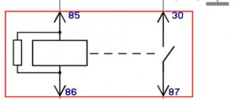
To extend the life of lamps in industrial environments, soft start systems are used. The presented scheme is the simplest. Here a relay and a resistor are placed in the gap of the existing lamp power supply circuit. The relay winding is powered in parallel with the lamp. How it works: after turning on the headlights, they light up dimly, like headlights, and after about half a second they turn on at full power. In this ignition mode, the lamps will last much longer, especially overheating (+50, +90, etc.).
Required:
- Relay (for each lamp) - You can use any 12-volt relay for a current of more than 5A, you can also use car relays.
- Resistor (nominal value 0.1-0.5 Ohm) - selected individually for the characteristics of the relay, so that the relay operates at the highest possible resistance value. You need to use a powerful ceramic resistor of about 5 Watts.
Placement: two relays can be installed anywhere (for example, under the hood near the headlights or in the fuse box).
Light sensor failure
As a rule, such devices rarely break down on their own. Provided that you have chosen a quality product from a well-known brand. When it comes to safety while driving, there is no need to skimp. Breakdowns are usually caused by factory defects, improper installation or improper use. It often happens that it takes many hours to find a fault, but the repair itself takes only a few minutes.
Many manufacturers indicate some restrictions for their products, so you should carefully read the instructions
As a rule, these are standard precautions: make sure that no moisture gets inside the device elements, protect them from mechanical and other influences. There are also sometimes recommendations not to use gas-discharge lamps on cars.
Kinds
So, let's move on to the types. In total there are 3 of them, depending on the power, as well as the type of light source. It should be noted right away that the disadvantage of a dimmer is its narrow relevance in a given situation.
But let's take a closer look at the main types:
- Devices for incandescent lamps and halogen lamps with a power of 220V. In this group, the most important thing is the power supply.
- Devices for low voltage halogen lamps.
- Devices for LED lamps. The main difference here is the structure of the dimmer itself.
Thus, it can be argued that you should not rush into a purchase, because initially you need to find out all the details regarding the use of certain light sources, their power, brightness and other characteristics.
Only after determining all the parameters should you proceed to the choice. To do this, it is best to consult with specialists who can suggest the best option in a given situation.
Now let's move on to another classification, depending on the control method. Species, as in the previous classification 3:
- sensory;
- push;
- rotary;
The manufacturing company also plays an important role. Prices for foreign models are often higher, but the quality is also high. But if you need a simple regulator, then you shouldn’t overpay more, because the device is in fact elementary, which means it will last well and for a long time.
Do-it-yourself automatic low-beam headlight switching
July 27, 2016. Category: Automotive equipment.
As you know, low beams must be turned on when driving a vehicle, not only in the evening and at night, but also during the day. In a situation where the running lights do not work, the traffic police officer has the right to issue a fine to the driver.
Of course, this is a small amount, but it creates a headache.
In this regard, most motorists have encountered a number of inconveniences due to the fact that many simply forget to turn on the low beams when getting into the car, or do not turn off the lights when leaving the car, which is why they find the battery completely discharged in the morning.
In order to get rid of such problems, many decide to modify the process of turning on and off the headlights. Thanks to the simplest circuits, the headlights can turn on simultaneously with the ignition or when the engine starts. In this case, during the daytime the low beam headlights will light up, but not the headlights, and at night everything will work as usual. Let's consider both options.
Automatic switching on of headlights upon ignition
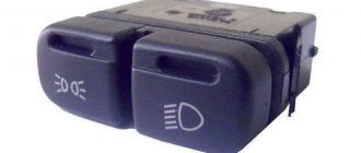
In order to organize such operation of the lighting elements, it is necessary to connect them to the ignition power source, and as many know, some devices can be connected at any position of the ignition switch, while others begin to function only when the ignition is already on. Based on this, the most convenient place to connect the headlights is the heater switch button (the rightmost switch block).
For this scheme you will need:
- any standard five-pin relay;
- diode;
- wires.
Next, we need:
- Remove the size switch (switch block on the leftmost side).
- Disconnect the positive wire from the key block responsible for the low beam operation (usually this is a green double wire) and connect it to the relay.
- You need to insert an additional wire into the positive wire that goes to the heater switch and also connect it to the relay.
- Connect the wire that powers the headlights to the relay.
- Throw the wiring to minus (to the body).
The connections can be soldered, but for full-fledged work, an ordinary insulated twist will suffice. As a result, automatic low beam headlights will work as soon as you turn on the ignition.
However, this method is considered not the most economical, since the headlights start working immediately, which is not very important in winter, when the engine needs to be warmed up or when repairing a car.
To avoid such inconveniences, you can complicate the circuit a little so that the low beam turns off while parked, regardless of whether the ignition is working or not.
Automatic switching on of headlights after engine start
To organize such a work scheme, you can go in two directions: connect to the oil pressure sensor or to the handbrake.
Method 1: Connecting to the oil pressure sensor
To make this connection you will need:
- relay;
- transistor (2 pieces);
- wires;
- microcircuit K561TP1.
All parts are placed in a small relay housing, after which the device must be connected to an oil pressure sensor. When the pressure in the engine lubrication system normalizes, that is, when the engine is turned on, the sensor will open, and the power from it will go to the capacitor.
Ultimately, the voltage to the relay will be supplied through the transistors included in the headlight power supply. When the engine is turned off, power from the sensor is supplied to the desired lamp located on the dashboard.
At this time, the capacitor that is included in the headlight control unit begins to discharge and the power supply to the relay stops.
True, not everyone likes this method, since this scheme is much more complicated (you need to pull wires and make 3-4 connections).
Method 2: Connecting to the handbrake
This method is much simpler, since in this case it is enough to just slightly modify the headlight connection diagram for ignition, which we talked about at the very beginning. To do this, just add another relay and a short wire (about 25 cm) to the standard contact of the handbrake button.
Thanks to this method, the headlights will turn off as soon as you pull the handbrake, and light up when you release it.
In custody
All these methods take a minimum of time and financial investment, and the result eliminates many troubles. Automating the process of turning on headlights does not require any special electrical skills, so you can handle this connection yourself without any problems.
Prospects for the use of lamps
Traditional light bulbs, which are now banned in many countries, could be making a comeback thanks to a technological breakthrough. Incandescent light bulbs, developed by Thomas Edison, produce light by heating a thin tungsten filament to a temperature of 2,700 degrees Celsius. This hot wire emits energy known as black body radiation, which represents a very wide spectrum of light, providing not just a warm light, but also the most accurate reproduction of all known colors of the universe. However, they have always suffered from one serious problem: more than 95% of the energy that goes into them is wasted as thermal energy.
Now, researchers from MIT and Purdue University have found a way to restore their former popularity and promise to create new MIT lamps with the efficiency of LEDs. It will work by placing nano-mirrors around a conventional element, which will return wasted heat back to produce light in the efficiency range of LED and fluorescent lamps.
The lamp element is surrounded by a system of nano-photonic mirrors on the cold side, which transmit visible light. But they reflect heat from infrared radiation. This heat is then absorbed by its element, causing it to emit more light. This original trick is very simple and viable. The tungsten element has also been changed - MIT uses tape instead of filament, which is better for absorbing reflected heat. The experiment, carried out by physicists Ognin Ilik, Marin Soljacic and John Joannopoulos, has already managed to triple its efficiency to 6.6%.
Scientists are confident that they can achieve 40% efficiency, which is at the upper limit of what is possible for any light source. Modern LEDs still reach the level of 15%.
And if scientists fulfill their ambitious promises, traditional lamps will deservedly rise from oblivion. Then smooth switching on and off of the light will be ensured by their design.
Overview of the main options and their features
We will look at how to automatically turn on the low beam in two ways, each of them has its own characteristics, and the choice ultimately depends on you.
Domestic manufacturers suggest using a special relay as a solution to the problem, its marking is 719.3777-01, with its help you can automatically turn on the low beam and side lights.
The following can be said about this option:
- The system is suitable for VAZs from the 4th to the 15th model, for example, the relay is installed for fog and regular headlights in the VAZ 2110, GAZ, UAZ and others, in which the low beam winding of the relay has a permanent connection to ground;
- The headlights light up approximately 5 seconds after the engine starts, which is very convenient, since, firstly, it makes it easier to start the engine, secondly, the load on the battery is significantly reduced, and thirdly, the life of the lamps increases;
- The lights turn off when the ignition is turned off, which is also very convenient, because now you won’t leave the car with the headlights on;
- If necessary, you can always turn off the light manually; to do this, the switch is flipped to the “low beam” position, and then placed in the “off” position.
Now let’s look at how to implement automatic switching on of low beam headlights with your own hands; the work is carried out in the following sequence:
First, you need to install a new unit instead of the low beam relay, and if you use mini-relays, you will need a special adapter, which should also be included in the kit, the whole process is as simple as possible and will not take much time;
By going through this process, you will get a convenient and reliable system that will prevent many problems.
Driver repair
First of all, check the fuse, if there is one. The device should show zero resistance. This can be done without removing the fuse from the board. Did the device show infinitely high resistance? Replace the fuse and plug in the lamp to test. Is it glowing? The renovation is complete. If the fuse is OK, we continue the repair. Check the diode bridge. You can find out in detail how to do this here.
Is the diode bridge working? Then unsolder the smoothing electrolytic capacitor and ring it. If the capacitor is working properly, then at the initial moment of continuity the multimeter will show a small resistance, which will grow before our eyes until it goes to infinity.
If the driver is simple, as often happens, then all these manipulations will certainly lead to success and completion of the repair. If the driver is more complex, then all you can do is ring the remaining electrolytic capacitors and diodes. It is easier to completely unsolder capacitors; only one terminal of a diode can be unsoldered. To make it lose contact with the board, it is enough to lift the device with a needle or tweezers.
If everything is in order here, then, alas, for further more complex repairs you will have to use the help of a qualified electronics engineer.