VAZ 2113, 2114, 2115 cars considered
Attention! The location of fuses and relays in the blocks may differ depending on the year of manufacture and vehicle equipment. You can see earlier modifications of fuse blocks on this page.
Fuses for the VAZ 2114 injector and VAZ 2115 injector are also described on this page.
Where are the fuses and relays located?
The main part of the fuses and relays is located in the mounting block of the engine compartment.
To get to the block you need to press two latches and remove the cover
Using pliers installed in the block, remove the fuses
On the inside of the cover there is a diagram of the location of fuses and relays.
Click on the image to enlarge.
Fuse mounting block 2114-3722010-60
leon1193 › Blog › Decoding the fuse box VAZ 2109-2114
Decoding the fuse block VAZ 2109 F9 (7.5 A)
Right fog light and fog light warning lamp
F8 (7.5 A
) Left fog light fuse
F1 (10 A)
Headlight wiper motors (at the moment of switching on), headlight wiper switch relay (contacts) and headlight washer switch valve
F7 (30 A)
Electric motors headlight cleaners (in operating mode).
Relay for turning on headlight wipers (winding). Electric motor for heater fan, washer pump, rear window wiper. Rear window washer timing relay. Rear window washer activation valve. Relay for the electric radiator cooling fan (winding) and for turning on the rear window heating. Indicator lamp for turning on the heated rear window and glove compartment lighting F16 (15 A)
Turn indicators, relay-breaker for turn indicators and hazard warning lights (in turn indicator mode).
Indicator lamp for turning on the turn signal. Rear lights (high-speed running lights). Windshield wiper motor and relay. Generator excitation winding (when starting the engine) and brake fluid level warning lamp F16 (15 A)
Fuse VAZ 2109 warning lamps: emergency oil pressure, closing the carburetor air damper, turning on the handbrake.
“STOP” display. Coolant temperature and fuel level indicators. Indicator lamp for reserve fuel remaining. Voltmeter. “CHECK ENGINE” indicator light. “TEST” board. Warning lamps for the on-board monitoring system, seat belts not fastened and doors not closed. Power circuit for inertial door lock switch F3 (10 A)
Rear lights (brake signal lamps).
Interior lighting F6 (30 A)
Electric window motor, power window relay
F10 (7.5 A)
License plate lights.
Engine compartment lamp. Instrument lighting lamps. Indicator lamp for turning on the side light. Heater lever illumination display. Cigarette lighter lamp Left headlight (side light). Left rear light - side light F5 (20 A)
Radiator cooling fan electric motor and its activation relay (contacts).
Sound signal and relay for its activation F11 (7.5 A)
Right headlight (side light).
Right rear light (side light) F2 (10 A)
Direction indicators, relay-breaker for direction indicators and hazard warning lights (in hazard warning mode).
Hazard warning light F4 (20 A)
Rear window heating element.
Relay for turning on the heated rear window (contacts). Socket for connecting a portable lamp. Cigarette lighter F15 (7.5 A)
Right headlight (high beam)
F14 (7.5 A)
Left headlight (high beam).
Indicator lamp for high beam headlights F13 (7.5 A)
Left headlight (low beam)
F12 (7.5 A)
Right headlight (low beam)
1 (8 A)
Reserve fuse in the VAZ 2109 block
2 (8 A)
Reserve
3 (8 A)
Electric motors of headlight wipers at the moment of switching on).
Relay for turning on headlight wipers (contacts). Headlight washer activation valve 4 (16 A)
Headlight wiper motors (in operating mode).
Relay for turning on headlight wipers (winding). Heater fan motor. Electric motors for the rear window washer and wiper pump. Rear window washer timing relay. Valve for turning on the windshield and rear window washer. Relay for the electric radiator cooling fan (winding) and for turning on the rear window heating. Indicator lamp for turning on the heated rear window and glove compartment lighting 5 (8 A)
Turn indicators, relay-breaker for turn indicators and hazard warning lights (in turn indicator mode).
Indicator lamp for turning on the turn signal. Rear lights (high-speed running lights). Windshield wiper motor and relay. Generator excitation winding (when starting the engine). Brake fluid level warning lamp. Indicator lamp for emergency oil pressure. Indicator lamp for covering the carburetor air damper. Indicator lamp for turning on the hand brake. “STOP” display. Coolant temperature gauge. Fuel level indicator. Indicator lamp for reserve fuel remaining. Voltmeter 6 (8 A)
Fuse for rear lights (brake signal lamps) in block 2109. Interior lighting
7 (8 A)
License plate lights.
Engine compartment lamp. Instrument lighting lamps. Indicator lamp for external lighting. Heater lever illumination display. Cigarette lighter lamp 8 (16 A)
Radiator cooling fan electric motor and its activation relay (contacts).
Sound signal and relay for its activation 9 (8 A)
Left headlight (side light).
Left rear light (side light) 10 (8 A)
Right headlight (side light).
Right rear light (side light) 11 (8 A)
Direction indicators, hazard warning relay-breaker (in hazard warning mode).
Hazard warning light 12 (16 A)
Rear window heating element.
Relay for turning on the heated rear window (contacts). Cartridge for connecting a portable lamp. Cigarette lighter 13 (8 A)
Right headlight (high beam)
14 (8 A)
Left headlight (high beam).
Indicator lamp for high beam headlights 15 (8 A)
Left headlight (low beam)
16 (8 A)
Right headlight (low beam)
Find out the radiator pipes from VAZ 2108 to VAZ 2115
Radiator pipes VAZ 2108, 2109, 21099, 2113, 2114, 2115…
Hello dear reader of the RtiIvaz.ru blog. Let's find out today and talk to you about which radiator pipes are installed on Lada VAZ 2108, 2109, 21099, 2113, 2114, 2115 cars.
Many car owners do not know what rubber radiator hoses for the cooling system are needed for and how they work. Here I’m trying to explain in simple language about RTI auto repair kits for vases, and also show on video what goes where.
Forgive me if I'm wrong somewhere, since the rubber pipes of the cooling system are very difficult to understand. As a car enthusiast, I will try to explain to you about the radiator pipes for the cooling system, which ones fit where.
Look at the photo and also at the video of the inlet, outlet, and bypass pipes. In general, you need to at least somehow understand the hoses on your Lada VAZ cars for a fulcrum under the hood.
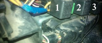
Next, see a photo of the pipes of the Lada VAZ 2108, 2109, 21099, 2113 for cars with a carburetor engine:
For VAZ cars with carburetor engines
Number 1 is the “upper” pipe that “supplies” coolant from the engine to the radiator, the so-called “wave”, has the shape of a wave.
And number 2 is the lower “angular” rubber pipe, which drains coolant from the radiator to the engine.
At numbers 3 and 4, there is one “short” one, a bypass connects the engine head to the thermostat, and the second connects the thermostat to the water pump. Expansion barrel pipe for carburetor engines number 5. Design numbers:
- 2108-1303025 radiator supply hose number -1
- 2108-1303010 outlet hose -2
- 2108 -1303092Р thermostat coupling numbered -3; 4
- 2108-1303080 cooling system filling hose with extension number -5
You are a car enthusiast, you probably know that the upper supply hose supplies hot liquid from the engine for cooling in the radiator. And the lower outlet hose carries the already cooled liquid to the engine. This is the unusual role played by the rubber hoses of the cooling system. Next, see a photo of the pipes of the Lada VAZ 2108, 2109, 21099, 2113, 2114, 2115 for cars with an injection engine:
For VAZ cars with injection engines
Number 1 is the “upper” pipe “supplying” coolant from the engine to the radiator, “angular wave”, has the shape of an angular wave. And number 2 is the “lower” coolant discharge pipe.
At number 3 is the “angle” bypass connected from the engine head to the thermostat and further to the water pump through the “short” coupling 4. At number 5 in the photo is the hose of the expansion barrel for injection engines.
Design numbers:
- 21082-1303025 radiator hose, supply number -1
- 21082-1303010 outlet hose - 2
- 2109-1303093-01 connecting hose for thermostat and water pump -3
- 2108 -1303092Р thermostat connecting coupling -4
- 21082-1303080 cooling system filling hose number -5
Video:
That an injection engine and a carburetor engine also have a “antifreeze” hose of the same length and thickness for removing steam from the radiator to the expansion tank (see video).
The steam exhaust hose “antifreeze” VAZ 2108-2115 differs from the steam exhaust hose VAZ 2110-2112 only in length.
What is the difference between auto repair kits for radiator pipes of injection and carburetor engines, I will not describe in this auto article, look friends, you can clearly see it in the photo and video.
- You might also be interested in:
- Adjusting valve clearances 2101
- Radiator pipes used on Lada
- Maintenance of the cooling system on a car
Operating principle, design and characteristics of fuses
A protective device of this type consists of a housing, which is usually made of high-strength ceramics or special glass, and a fusible insert made of a conductive metal or alloy.
The body performs several functions:
- a fuse-link is built into it in a special way so that when the rated current of the insert is exceeded, it melts or breaks;
- the working thread is inserted into the chamber to extinguish the electric arc that occurs when the circuit breaks; this chamber is equipped in the housing;
- on the body, in those places and in the form as provided for by the fuse design, there are working contacts through which it must be connected to the general network.
Information about the characteristics of this protective device is printed on the housing. This is the rated current of the fuse link and the rated current of the fuse body at which it breaks.
According to their performance characteristics, these protective elements are divided into:
- fast-acting;
- low voltage;
- designed for medium voltage;
- manufactured for high voltages.
In automotive networks, the first two types are used.
The defining point showing the purpose of a particular protective device with a fuse link is its current characteristics. It is she who speaks about the range in which this element is ready to work.
- To protect electric motors, fuses are installed whose inserts can withstand the rated current and its excess for a sufficiently long time necessary to start the main mechanism and reach its operating range. As a rule, such chargers (protective devices) are marked - g - as devices ready for protection from both overload and short circuit.
- There are protective devices that operate effectively during short circuits and protect all equipment from very high voltage currents. Such chargers are marked - a - for protection only against short circuits.
Fuses for cars have several versions:
- low-current inserts, in networks up to 20 A, made of glass with a thin wire insert, there are ceramic cases, the ends are made of metal;
- fork inserts, most commonly used in vehicles, come in miniature and regular types.
According to GOST, a painting system for fusible chargers has been adopted depending on the rated current of the insert. 2 A - gray, 4 A - pink, 5 A - orange-yellow, 7.5 A - brown, 10 A - red, 15 A - blue, 20 A - yellow, 25 A - white, 30 A - green.
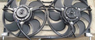
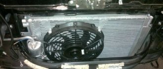
Selecting additional fans.
Before purchasing and installing additional fans, carefully examine your computer. Open the case cover, count and find out the dimensions of the mounting locations for additional case coolers. Look carefully at the motherboard to see what connectors it has for connecting additional fans. Fans should be selected in the largest size that suits you. For standard cases this size is 80x80mm. But quite often (especially recently) fans of sizes 92x92 and 120x120 mm can be installed in cases. With the same electrical characteristics, a large fan will operate much quieter.
Try to buy fans with more blades - they are also quieter. Pay attention to the stickers - they indicate the noise level. If the motherboard has 4-pin connectors for powering coolers, then buy four-wire fans. They are very quiet, and their automatic speed control range is quite wide.
Between fans receiving power from the power supply via a Molex connector
and running from the motherboard, definitely choose the second option. There are fans on sale with real ball bearings - this is the best option in terms of durability.
( 2 ratings, average 4 out of 5 )
VAZ 2114 fuse box
On cars of the Samara 2 series, which include the VAZ 2114, there is a mounting block that is installed in the engine compartment under the windshield on the left side.
Location of the fuse box on the VAZ 2114
It houses various relays and fuses. Because of this, it is often called the fuse box. The cover of the mounting block is secured with clips made of plastic; they snap off quite easily and it is removed. On its inner side there is a diagram of the VAZ 2114 fuses. The rated current strength that is allowed in the circuit for each protective device is indicated there.
You cannot install a charger with a current exceeding the rated values indicated in the diagram. In this case, damage to the electrical device located in the circuit is possible.
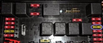
On injection machines, the relays and chargers are located as follows.
Fuse box VAZ 2114
In the upper right corner you can see a small yellow tweezer; it is specially attached there for replacing the charger.
In total, this block contains 17 active memory units from F1 to F16 and 4 reserve ones - F17, F18, F19 and F20.
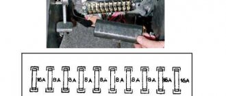
In addition, the car has another block where the fuses are located; it is located in the car interior under the glove compartment and an open shelf.
The interior is equipped with:
- Charger for the fuel pump, with a rated insert current of 15 A;
- protection (7.5 A) on the fan relay, speed sensor, oxygen sensor, mass air flow sensor;
- fuse with a current of 7.5 A to protect the ECU and ignition unit.
Fuses under the right screen of the VAZ 2114 console
In order to competently operate the electrical equipment of a car and promptly respond to emerging malfunctions or failures, you need to have a good understanding of which circuits include a particular protective device.
Forced fan start via BIOS
To make your laptop cooler work more efficiently, you can change its speed and set the CPU temperature it needs to maintain. To do this you need to do the following:
- Enter BIOS. When booting the laptop, press the Del, F8 or F12 key. It all depends on the motherboard model. If your PC uses the quick startup function of the OS, then to launch the BIOS you will first need to go to the “Power Options” section and in the “Actions of the Power Buttons” tab, uncheck the box next to the “Enable quick startup” line.
- Open the “Power” menu and go to the Hardware Monitor tab.
- Specify at what power the cooler should operate (set as a percentage of the maximum value), or activate the intelligent mode of operation of the cooling system.
- Leave the BIOS after saving the changes you made.
The software shell of the Hardware Monitor tab may differ in different BIOS builds. However, if you know what parameters need to be changed, you can easily switch the fan to the required operating mode:
- in the CPU FAN speed line it is written at what speed the cooler will rotate;
- CPU Temperature controls the CPU temperature that the fan will maintain;
- CPU Q-Fan Control starts the intelligent operation mode of the laptop cooling unit (you need to put Enable opposite this line).
In intelligent mode, the cooler can operate with the following parameters:
- Silent – the emphasis is on silent operation of the system and saving battery power;
- Standard – the fan will operate at half its capacity;
- Performance and Turbo – the fan is overclocked to its maximum (in this case, the battery life of the laptop will be slightly reduced, since the cooler will consume a lot of energy).
Purpose of fuses
What fuses are on the VAZ 2114? The electrical circuit of this car is designed in such a way that in front of all the main electrical units there are chargers located in the fuse box.
VAZ 2114 fuse diagram
The connection diagram of these protective devices is shown in the figure.
- F1 - rated insert current 10 A - protects the fog lamps located at the rear.
- F2 - with a current of 10 A - these are left and right turn lights, an emergency warning light, a relay-breaker for turn lights and emergency lights.
- F3 - with a current of 7.5 A - protection of light bulbs in the cabin and trunk, trip computer circuits, ignition and brake lights, "Check engine" warning light.
- F4 - with a current of 20 A - protects switches located in the heating circuit of the trunk door glass and heating elements of this glass, “carrying” contacts.
- F5 - with a current of 20 A - protects the horn circuit and its switch, as well as the electric motor of the cooling system fan.
- F6 - with a current of 30 A - this is a circuit of electric windows and their switches with contacts.
- F7 - with a current of 30 A - a protective device for three electrical units - a heater, a windshield washer and a headlight cleaner. In addition, there is also a cigarette lighter, glove compartment lighting and winding for the heating switch for the trunk door glass.
- F8 - with a current of 7.5 A - is protection for the right fog light bulb located in front.
- F9 - with a current of 7.5 A - this is protection for the left fog light bulb located in front.
- F10 - with a current of 7.5 A - protects the indicator lights on the left side, the license plate number, the engine compartment light, the dashboard lights and switches with heating levers, as well as the indicator lights for the size.
- F11 - with a current of 7.5 A - protects the right-side headlight bulbs.
- F12 - with a current of 7.5 A - a protective device for the right low beam headlight bulb.
- F13 - with a current of 7.5 A - a protective device for the left low beam headlight bulb.
- F14 - with a current of 7.5 A - protects the left high beam headlight and the blue high beam warning light.
- F15 - with a current of 7.5 A - protects the right high beam headlight.
- F16 - with a current of 15 A - protects the light bulbs and the turn switch and hazard warning lights, the white reverse light, the power supply of the instrument cluster, the trip computer, the generator winding (at startup), the lights indicating low oil pressure, brake fluid and parking brake, battery discharge.
Cooling System Maintenance
In order for the cooling system to function properly, it must be maintained and its condition periodically checked. The most important of these operations is the timely replacement of coolant. It is due to the fact that during circulation through the coolant system it undergoes repeated heating and cooling, as a result of which its chemical composition changes and the cooling properties sharply decrease.
In order to replace the coolant on time, you need to focus on the following important rules:
- Antifreeze should be completely changed every 2 years, and antifreeze - every 5 years;
- with high mileage, replacing antifreeze is required after approximately 15,000 km, and antifreeze after 40,000 km (these figures may be slightly more or less, depending on external conditions);
- If there is a significant change in the color of the coolant, it must be replaced, regardless of the time of use and mileage.
As you can see from the above rules, the use of antifreeze is more profitable, and preference should be given to it.
Coolant replacement
In order to avoid serious mistakes, correct coolant replacement should be done as follows:
- Completely drain all old coolant from the system.
- Tighten all plugs tightly.
- Fill the system with purified (distilled) water up to the maximum mark.
- Start the engine and let the system warm up well (overheating of the engine should be avoided, and the idle speed should be maintained around 3000).
- Turn off the engine and leave the car to stand for about 7-10 minutes.
- Drain all distilled water from the system.
- If the water flows out dirty, repeat the entire operation again.
- After clean water begins to flow out, pour coolant into the system.
If during the operation of the car the coolant level drops, then it can be periodically topped up, but after the allotted time (the timing was indicated above), it is still necessary to completely replace it.
Possible breakdowns
As for breakdowns in the cooling system, the most common occurrences are:
- problems with the radiator (leakage or blockage);
- thermostat failure;
- destruction of the water pump (most often the bearings fail or the impeller breaks off);
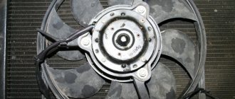
- fan failure;
- leakage in the pipe system.
Cooling system pipes
While problems with the radiator and other components of the system cannot be solved in one minute, problems with pipes can be quite easily eliminated - if they have lost their elasticity and began to crack, then they should simply be replaced with new ones. And in most cases, simply tightening the clamps will be enough to solve the problem of coolant leaks from the cooling system.
Replacing fuses on a VAZ 2114
When any problems are detected in the operation of the car’s electrical network and engine, be it the burnout of light bulbs or the failure of some electrical devices, the driver must first check the functionality of the fuses. The procedure is as follows:
- determine where the fuses are located on the VAZ 2114, which may have failed. To do this, look in the machine’s operating manual for a diagram of the location of the protective devices and determine whether they are located in the mounting block or under the dashboard in the area where the front passenger’s feet are located;
- when working with the car's electrical system, the negative contact of the battery must be disconnected;
- open the plastic latches holding the mounting block cover;
- remove the plastic tweezers from the mount in the upper right part of the block; they can be red, transparent or yellow;
- take the protective device, the circuit of which is supposed to be broken, by the body with tweezers and pull out the fuse;
- There are rules, developed by operating experience, on how to check the fuse. First of all, it is necessary to visually determine whether the fuse-link inside the case has burned out or whether the charger is in good condition;
- if the destruction of the insert cannot be visually determined, it is necessary to check the protective device using a device;
- If confirmation is received that the fuse has blown, it must be replaced with a functional one. The price for a VAZ 2114 fuse box on the automotive market is about 2,000 rubles, and a set of separate chargers of this type will cost 150 -250 rubles.
It is strictly forbidden to install home-made devices or jumpers in place of failed chargers, as well as fuses with a different rated insert current. A short circuit or fire may occur.
When working with the mounting block, do not use metal screwdrivers or other metal tools, this can lead to a short circuit and failure of the mounting tracks of the block.
We invite you to watch this useful video:
Ways to control the operation of a cooler on a laptop
In laptop computers, the BIOS is responsible for the normal functioning of the cooling system. At the same time, the factory settings provide for the fan to operate at only 50% of its maximum power . This is done so that during operation the cooler does not buzz too much and does not consume a lot of electricity.
Almost all motherboards provide the ability to programmatically control the performance of the cooling system. There are several ways to force the fan on your laptop:
- Via BIOS.
- Using special software.
Changing the cooler settings can lead to unpleasant noise during its operation, as well as accelerated battery drain. Therefore, before taking radical measures, you should disassemble the laptop, and then clean the fan and motherboard from dust, because it reduces heat transfer and, accordingly, leads to an increase in the temperature of the PC.
https://youtu.be/https://youtu.be/wdpTUvxVWFU
_
Fuse box diagram and location on VAZ-2114, 2115 and 2113
Remember one important thing, before you start disassembling the stove, wiper, headlight or anything else - make sure that the fuse responsible for this circuit has not blown