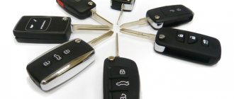
Combining safety and convenience. Varieties of control methods
The advantages and benefits of remote locking systems are now known even to the inexperienced car owner.
Although there are still many cars that are not equipped with such systems, their popularity has affected even the most conservative driver. You should see it once and try it - there will be no more questions.
The most persistent of drivers deciding whether to install this system, and those who want to have maximum convenience at a minimum cost, can be recommended to install electric locks only on the front (most frequently used) doors. The amenities are almost the same, but the level of security is lower due to the fact that the owner may still sometimes forget to lock the rear doors manually.
The combination of vehicle safety and user convenience will be most complete when the remote locking system is “linked” to the car alarm. This will provide the following benefits:
- the level of vehicle security increases, since simultaneously with the remote activation of the security mode, all doors are automatically locked;
- the reliability of vehicle protection increases, since after the driver exits the vehicle, automatic door locking can be activated (passive activation with door locking);
- The personal safety of the driver and passengers increases when the doors are locked when the ignition is turned on.
The information material below not only introduces an almost complete set of connection diagram options, but, most importantly, in our opinion, helps solve the three main problems that arise when implementing any remote locking system:
- determine what type of central locking is installed on the car;
- “match” the central locking with the car alarm;
- connect door lock control buttons.
GENERAL INFORMATION
The main elements of remote locking systems are door lock drives (actuators) and controllers - special control devices.
The most common door lock drives are electric drives, which we will consider in more detail.
Special control devices, often called central locking controllers, usually installed by the car manufacturer, provide simultaneous unlocking and locking of all car doors (possibly, at first, only the driver's door) using a central button or a regular car key. (We will also include some elements built into the car alarm and used to remotely control the locks as a central locking controller).
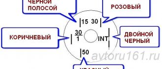
During installation, special attention should be paid to the method of connecting the buttons (either newly installed or already installed in the car). The given diagrams of two types of buttons can help solve this problem. When one side of the double button is pressed, only one moving contact switches to the position indicated by the dotted line.
The second moving contact remains in its original position and will switch to the dotted position when the second side of the button is pressed.
When one side of the single button is pressed, the moving contact switches to the dotted position and, when released, returns to its original position.
Electric door lock drives (actuators)
Electric drives (electric motors) for door locks are available in several design options, differing in the value of traction force (from 2.5 to 6 kg).
All of them use DC electric motors and plastic (or metal) gearboxes built into a plastic housing, converting rotational motion into linear motion. The direction of translational movement of the motor output rod is changed by reversing the polarity of the supply voltage, which is how the door lock is unlocked or locked. The most common electric motors are T-shaped (“pistol”) and square types.
The electric motors of the locks are controlled by a pulse voltage lasting 1 s. Electric motors differ in the presence or absence of a contact microswitch, mechanically connected to a retractable rod. The three wires of this microswitch are led out and, together with the two supply wires of the engine itself, form the so-called five-wire “master motor”, usually installed in the front doors. The microswitch built into them, together with the control unit, ensures that the rear door electric drives are activated when the front door lock is manually unlocked/locked using a regular car door key or door button.
A type of lock is a “master lock”, which has a locking mechanism that prevents the lock from being unlocked using the door button (lever). This type of lock can only be unlocked electrically.
A complete door motor kit includes 2 5-wire master motors, 2 or more 2-wire conventional motors (without switch), and a control controller (module).
A type of electric lock drive has appeared, which has an electromechanical fixation of the output rod in a locked state, preventing the thief from opening the door using any mechanical device. The normal opening of such a lock is carried out by two successive impulses (the so-called “two-stage unlocking”). This type of unlocking is provided in the central locking controllers built into car alarm systems for both Top Line (Cel, Ireland) and Internet (Internet Auto Security, USA) systems.
Typical characteristics
Traction force, kg - 2.5-3.5; Stroke of the output rod, mm - 19; Force for manual unlocking/locking, kg - 0.25-0.14; Current consumption, A - 2-3; Control pulse duration, s - 0.7-1.5; Dimensions, mm - 134x60x30.
Central locking controllers
Purpose and types of controllers
Central locking controllers provide:
- automatic door locking when the car alarm is armed;
- automatic unlocking of door locks when the vehicle is disarmed.
Additional functions of the central locking controller can perform:
- locking/unlocking the rear door lock when locking/unlocking the front door with a car key or door lever (button);
- locking/unlocking door locks when turning the ignition on/off.
The controllers are interfaced with electric lock drives directly or through microswitches of electric door drives. Car manufacturers produce a number of cars with central locks (controllers) installed on them. The most universal controllers provide the setting of different locking and unlocking times. The main task for obtaining automatic control of door locks when installing a car alarm is the selection of the appropriate car alarm, as well as the correct way to connect it to the central locking of the car (if it is already installed).
It is necessary to distinguish between three types of car alarms with built-in central locking functions according to the capabilities they provide for controlling door locks.
First view. Car alarm with built-in full-featured central locking controller.
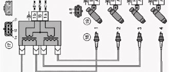
Such a built-in controller has two powerful relays (each with switching contacts) with a permissible current load of 10-20 A. To ensure automatic unlocking/locking of the rear door lock when opening (locking) the front door with a car key or lever (button), as a rule, two negative synchronizing inputs for connection to the “master electric drive” (Fig. 1). The total number of lock wires is 8. The car alarms SIRIO 777, CLIPPER 80/4, 80/6, MICROCAR ALARM 052. 1, SERPI STAR GR-44, SERPI STAR GR-440 and others have a fully functional controller.
Second view. Car alarms with built-in central locking have the same functions as the first type, but they do not have synchronizing inputs. The total number of lock wires is 6. This type of central lock is available in car alarms PYTHON System 80, Puranha PRM 18, Clifford XL100, Flash Point 600, Enforcer 600, Mongoose, Mega 3000, Ungo.
Third type. This type of car alarm controller has an electronic circuit with low-power outputs with a permissible current load of 200-300 mA, sufficient to connect to them, if necessary, standard relays or car central locking inputs. The number of outputs is 2. The outputs, in most cases, have negative signal polarity, but there are also bipolar ones. Low-power locking controller outputs are provided in car alarms VIPER Code Plus, Enforcer 100A5, 200A5, 300V, FORCE 7002 and others.
Standalone lock controllers
Autonomous lock controllers include devices that are interfaced with car alarms and perform the functions of a central lock. Such controllers have two main versions:
- with one control input;
- with two control inputs.
Controller with one control input
Converts the negative output of the car alarm blocking into pulse signals from the contacts of two powerful relays, one of which occurs at the moment the security mode is turned on, and the other at the moment it is disarmed. These pulses provide control of the lock motors.
The controller often has additional negative clock inputs connected to the "master" motor. This controller is used with car alarms that do not have standard outputs for central locking.
The M3 controller, which has both potential and pulse outputs, is produced by Spal, and the MC 2050 controller is produced by Autotecnica.
Controller with two control inputs
The controller is used to convert two pulsed low-power control signals into pulsed high-power relay signals. Essentially contains two standard relays with switching contacts, the windings of which are connected to the control inputs. Used to increase the power of central locking outputs for car alarms of the third type, discussed above. Controllers of this type are produced by many companies (for example, the M4 controller from Spal).
Typical characteristics
Pulse duration
- — for electric drive control: 0.7 — 7 s.;
- — for “vacuum”) control: 3.5 — 6 s.;
- — for “comfort” type control (closing windows and sunroof) — 30 s.
Current load - 15 A. Current consumption - 10 mA.
Options for central locking connection diagrams
There are seven main options for central locking connection diagrams. These options are formed depending on the polarity of control signals and the type of switches (buttons) of the central locking system. For ease of use with any type of car alarm, the diagrams of these options have, where necessary, contact designations for standard car relays. All electric drives are usually connected in parallel to each other. The only exceptions are systems that have the ability to initially unlock only the driver's door.
Selection of car alarms and connection diagrams
When choosing a door lock control option, the following sequence is recommended:
- Determine the type and polarity of control of the central lock installed on the car;
- Determine the type and polarity of the central locking switch (button);
- Determine whether a lock motor is installed in the driver's door;
- Choose the most suitable type of car alarm: with a full-featured central locking controller, with a central locking without synchronizing inputs or with low-power outputs for the central locking;
- Select the appropriate connection diagram from the options presented or modify it for your specific application.
Let's point out two simple options that may be useful.
A. The car does not have central locking. It is recommended to choose a car alarm with a built-in central locking controller that has powerful outputs from relay contacts.
B. The car is equipped with a central locking system with negative control, but it is required to control it from the car alarm. We recommend choosing a car alarm with low-power negative outputs for the central locking.
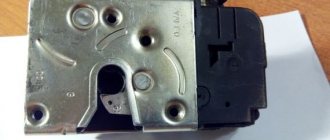
When to change the lock
So, the need to replace the standard factory lock with a modified one arises in the following cases:
If you suspect that someone tried to steal your car. As a rule, inexperienced car thieves can only damage the lock, as evidenced by the following signs: • The front door lock began to dangle, which was not the case before; • The key turns with difficulty, naturally, the doors are not easy to open; • There is visually noticeable damage in the lock area and/or near it; • You cannot open the front door at all with your own key;
You have lost your keys. Even if you have a spare set, this fact should alert you. Maybe the keys were not lost at all, but stolen, and now car theft is a real danger. In this situation (as well as in the case of the “inexplicable” loss of house keys), for most, a replacement is an indispensable condition for sleeping peacefully. By the way, in such a situation, perhaps only the larva will be replaced, which is cheaper and less work. The cylinder is the internal door mechanism, which is actually turned with a key. It is as individual and unique as the key itself. Thus, without disassembling the entire mechanism (which is discussed below), you can carry out this small repair in order to have a completely new lock for opening the front door;
Accidentally, mechanically, you broke something in the front door lock mechanism
For example, changing the upholstery, making careless adjustments, etc. After all, the design of the lock is such that it is not limited to only the visible part, but has locking parts directly under the door trim; You want to make the lock more reliable by increasing its protective properties, for which you carry out repairs and modifications.
TYPE A. Positive Control
This type of control is characterized by the positive polarity of control pulses. In Fig. 2 and 4 show diagrams for a car in which a central locking controller is already installed by the manufacturer, and pairing with the car alarm is carried out through relays built into it. In Fig. Figure 3 shows an option for pairing with a car alarm system that has low-power negative outputs that are connected to additional relays.
This type of control is typical for cars from General Motors Corp., Renault, Chrysler, VW Passat and some Ford models.
If you look at the switch installed in the driver's door that controls the locks, there will be three wires coming from it: a lock wire, an unlock wire, and a positive wire that is permanently connected to +12 V.
The unlocking and locking wires will have a potential of +12 V during locking and unlocking. When these wires are connected to a car alarm, a short-term positive potential (pulse) will appear on them.
Problem in the operation of the central locking electrical circuit on VAZ cars
The first possible problem follows smoothly from those mentioned in the previous section. Overload in the operation of activators leads to an increase in the operating current in the supply circuit above the rated value. As a result, the fuse blows and the central locking of the VAZ 2110 simply “dies”.
It is by checking the fuse that the diagnosis of central locking malfunctions begins. By the way, it is located in a very specific place and it is not easy to find it right away even if you know where to look. In order to get to it, you will need to fold back the central panel with the fuses and dig into the entire wiring harness in the niche that opens behind it. The “comrade” you need is packaged in a special plastic cup and connected to the pink wire.
Central locking unit VAZ 2110
Another very common and obvious problem is the central locking connector. It is located in the most unfavorable place for this in the interior body, under the foot mat. A large amount of moisture and dirt inevitably gets there. Electrical contacts are intensively oxidized. As a result, the power supply circuit involuntarily breaks at the point where the plug connector is connected.
TYPE B. Negative control
This is the simplest standard type of door lock control. It is used in cars from Fiat, Lanchia, Volvo, Citroen, BMW (pre-89), Toyota, Honda and others. If you look at the switch installed in the driver's door that controls the locks, there will be three wires coming from it: a locking wire, an unlocking wire, and a negative wire that is permanently connected to ground.
The unlocking and locking wires will be at ground potential while locking and unlocking the locks. When these wires are connected to a car alarm, a short-term negative ground pulse will appear on these wires.
Scheme in Fig. 5 shows the connection of the system to a car that does not have central locking and a lock drive.
Schemes in Fig. 6, 7, 8 are shown for car alarms with low-power control outputs, and Fig. 9, 10 - for powerful relay outputs built into car alarms. In Fig. 7 shows how to make a connection with protection against unlocking the rear doors by children.
Notes for Toyota vehicles: Many Toyota models have a lock control system with additional protection that prevents children from unlocking the rear doors. In this case, you need to keep in mind the following: if the door locks are locked by the car alarm command, then they can be unlocked by another command. But if the door locks are locked using the driver's door switch and the security system is turned on, then they cannot be unlocked by the car alarm command. This occurs because the security switch blocks the unlocking signal.
To make the correct connection, it is necessary to use decoupling diodes installed in the release wire circuit (Fig. 7).
The wire for this protection can be found in the common lock control wiring connector. Color chart for protection wires (the protection wire is located under the side panel trim at the driver’s feet).
| Toyota car model | Wire color |
| Camry | Blue red |
| Celica | Green |
| Cressida | Light green |
| MR-2 | Blue red |
| Sypra | White blue |
| PickUp | Red Blue |
| 4-Runner | Red Blue |
| Land Cruiser | Blue\orange |
central locking
I decided to install a central locking system and connect it to the signaling system, I will describe everything in stages.
Tools:
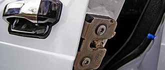
To begin, we remove the door, remove the trim, the handle, the window lifter handle and the plug from the door handle.
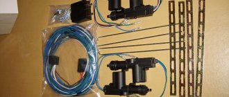
Next, you can begin installing the actuator.
Personally, I attached the actuators to the included strips:
Why is this so? Because it was just enough to secure the length of the rod included in the kit and there was no need to add anything - shamanism. Some do this:
but then you will need to select and place a washer, nut or something else under the lower mount so that the actuator does not warp, it seemed to me that it would be easier and more reliable to use the bar.
In the open position of the door (pulled out) we pull out the acuator to the maximum and, using the included fastener, we hook the rods and screw in the bolts.
Now it is advisable to check the actuator so that it opens and closes the door freely. Just connect the wires to positive and ground, change the polarity and check the opening and closing. If everything is ok. We put it in the second door in the same way.
For convenience, unscrew the door stops
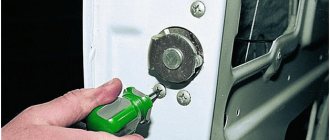
We drill a hole in the place we like, I drilled with a 10m drill. It's better to drill a hole in the door first.
We select a place so that it does not touch the seal and so on.
We close the door and draw or scratch a post from the inside of the door through this hole so that the second hole is coaxial and there is no bending of the wires when the door is closed.
Next, we drill the holes to the required size so that the rubber tube fits freely into it, the hole in the rack should not be much larger, so you will also need to insert the tube seal. We check whether the holes were made correctly, whether the wires will bend when closing the door.
We pull the wires, it’s easier in the passenger door, there is a hole in the glove compartment on the right, there is a wire going there to the door limit switch. We throw wires into it, lower them along the stand and catch them in the hole. For convenience, the end switch itself can be unscrewed so that the wires do not get caught once again and you can see whether the wires are running or not.
In the driver's room it is not much more complicated, you need to pull out the speedometer and run the wires through its hole into the same hole on the left, in principle it is not difficult to do by touch.
It is better to tie the wires with electrical tape to make it more convenient and avoid pulling them one by one.
We put rubber tubes on the wires.
We put it in the door hole.
We check how the tube moves in the door, whether it is loose or bent. open the door to the maximum and you can cut off the excess.
TYPE C. Polarity reversal control
This control method is used in Chrysler, Ford, Chevy Cavalier (95-96), BMW 325 (95) cars. This type of control is often confused with 3-wire positive control. This occurs due to the fact that positive control pulses appear on the wires of both systems. The difference is that the unlocking and locking wires in this control option, in the initial state, have mass, but in option A they have an indefinite (floating) potential.
This type of control does not have factory relays installed. The control switch directly controls the electric door drives, changing the direction of the current in their winding. Therefore, when using this control circuit, it is necessary to use external relays. During installation, you must be especially careful, because incorrect connections will lead to immediate damage to system elements. As protection, it is necessary to use a 3 A fuse in the +12 V power supply circuit.
If you look at the switch installed in the driver's door that controls the locks, there will be five wires coming from it: one wire with constant +12 V power, two wires showing constant ground and two wires having ground in the initial state, and a pulsed positive potential at locking or unlocking when the switch is pressed.
Example. When the Lock switch is pressed, the lock wire will have +12 V, the second unlock wire will be in its original state and ground.
When the Unlock switch is pressed, the polarity on the second wire will be reversed to +12V and the lock wire will be ground.
It is extremely important to determine which of the two reversing wires is the unlocking wire and which is the locking wire.
Recommendations for connection.
- Cut the locking wire;
- Press both ends of the Lock and Unlock switch alternately. If you cut the correct wire, the door locks will not lock or unlock. If the door locks operate in any other direction, then you have cut the wrong wire or the system does not have polarity reversal control;
- Refer to the illustration to determine which end of the wire goes to the lock switch and which to the motor. To do this, press and hold the Lock switch (make sure it is the right side) and the end of the wire from the switch will have +12 V. Connect this end of the wire to terminal 87A of the lock relay. The other end of the wire will come from the electric motor. Connect it to terminal 30 of the locking relay.
- Cut the release wire. This wire will have +12V when the Unlock switch is pressed. Once cut, the system will also not work in any direction.
Repeat the procedure for recognizing the ends of the cut wire. Connect the end from the switch to terminal 87A of the unlocking relay and the end from the electric drive to terminal 30 of the same relay.
Let's make the alarm system and central locking together
Any modern alarm unit is equipped with two relays connected to the central locking control unit. One relay is opening, the second is locking, and the circuit in the general case looks like this:
In our case, the green and white cords coming from the signaling unit will be required, as indicated in the diagram. However, they will not be the only ones needed. We will connect the relay contacts to breaks in the standard wiring. This means there will be not 2, but 4 cords.
Connection diagram for VAZ central locker
Take another look at the diagram published in the first chapter. We will connect the relay to the gap in the white and brown wires going from the microswitch to the central lock control unit. And it is obvious that it is easier to break these wires near the 8-pin connector. The same one shown at the beginning.
To avoid any questions, we will show you what should happen as a result:
Connection diagram, central lock VAZ
The common contacts are connected to the wires coming out of the microphone. The white cord continues with the brown wire coming from the door, and so on. Normally closed contacts are also used, along with normally open ones. These are the features of connecting to the VAZ central locking system.
An approximate sequence of actions performed by the installer:
- Make and lay a 4-core cable running from the signaling unit to the 8-pin connector;
- Connect the cable on the side of the alarm unit (see the last diagram);
- Near the 8-pin connector, disconnect the white and brown wires coming from the microswitch (pins 5 and 7). The main thing is not to confuse them with the wires going to the triangular connector “C”;
- Make connections to the broken wires, white and brown. That's all.
We have given this sequence to emphasize once again that the relays are switched on between the microphone and the central lock control unit. There is no need to connect any additional devices. As a result, the alarm system will be able to control the state of the locks.
All wires added to the car structure must be protected (use heat-resistant tubes or electrical tape). Twisting is not the worst method to connect two wires. But it's even better to use soldering.
It would seem that if a person has experience working with electrical equipment, he can do everything according to the instructions given. As a result, if no mistakes are made, you may encounter an interesting phenomenon. Instead of closing, there will be a short-term locking followed by opening. And vice versa. What to do in this case?
Take a look at what exactly may be present in some of the configurations:
The driver's door may not have an actuator. And then, it is useless to connect the signaling system to the control unit. There is no actuator, which means there is no one to close or open the door and move the microphone lever. Let's say the locks are closed, and then we remove ground from the brown wire and we get the following: the white wire is on ground, unlocking occurs.
We note the following: installation can only be carried out when you are sure that there is an actuator in the driver's door.
There were configurations where only a microswitch was installed. There is no need for arrogance here - adding an actuator will be difficult, since standard wiring must go to it. As you understand, it may not be available from the factory. And it’s unclear what to do then.
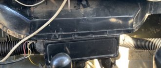
There remains one unanswered question - where exactly the central locking control unit is located. In these VAZ models, if there is a central locking system, then there is also a control unit. And it is located under the torpedo cover, next to the driver, on the right:
We remove the “beard” of the torpedo and look at what is on the upper right. On the same plane with the radio connector there are two boxes attached - the one we need, as well as the immobilizer (if there is one).
We would be lying if we did not say that in reality there is another option for installing the alarm. Standardly, only two power cables go to the actuators. Having a power outlet equipped with a fuse, these cables are connected directly to the alarm relay. This option, as you might guess, is not recommended. Imagine what would happen if the alarm system broke. The central lock must remain, but in this case this will not be done. Happy connection!
TYPE D. Special positive control
This type of control is highlighted separately as it applies to cars with central locking, but without an electric drive in the driver's door. Central locking is provided by a microswitch installed in the driver's door. For remote control, the microswitch in the door is removed and a five-wire drive is installed in it. The wires from the drive microswitch are connected to the wires of the removed microswitch (Fig. 13).
Repair features
As a rule, in the event of a central locking malfunction, experienced electricians first check the condition of the sensors. If the central locking system is connected to the anti-theft system, then it is this system that is checked first. As stated above, activators most often fail, so they should also be checked.
If a certain door refuses to work, the reason must be found in it. This could be the solenoid itself or the wires. During the operation of the car and the frequent opening and closing of doors, a break in the wiring circuit may occur due to kinking and mechanical breakdown of the wire itself. If this is the case, then the wire needs to be replaced or the broken parts reconnected, and then insulated.
TYPE E. Vacuum control
This type of system uses a compressor to open and close the door locks. Used in Mercedes and Audi cars.
Depending on what signal the compressor receives from the lock drives, they can be push or pull type.
When using this type of system, first of all, you need to find and cut the wire that controls the compressor.
WARNING. To determine the purpose of the ends of the cut wire, you should only use a voltmeter (do not use a test lamp). It is very important to identify and not mix up the ends of the wires going to the compressor and to the lock switch (you must label them). Due to an error in determining the sides of the wire, the compressor may be damaged.
NOTE. On most Mercedes Benz vehicles, the compressor control wire will be green or blue and can be found under the side panel trim near the driver's feet. This wire will have +12V when the doors are unlocked and ground when the doors are locked.
Reasons for replacing the lock cylinder
Blocking of the internal or external mechanism occurs due to improper operation, burglary or severe frost. Prerequisites for the device to break soon: creaking, difficulty turning the key, the rod has difficulty entering/exiting the core. At such moments, the larva can be saved if you go through it: apply lubricant to individual elements and remove contaminants.
For VAZ 2110, replacing the driver's door lock cylinder will be required when:
- climatic changes;
- failure of the locking ring;
- pin falling out;
- violation of the integrity of the thrust cap;
- wear of columns or teeth.
If individual fragments malfunction, they begin to cling to each other, blocking the rotation function. In winter, moisture often gets into the core and freezes. Because of this, the key turns with difficulty, jams the unlocking mechanism, or becomes blocked. Repairs have to be carried out from the passenger compartment and entered into the car through the back door.
TYPE F. Single Wire Positive Control
Control is achieved by changing the level of positive potential on a single-wire line. This type of control is used on Ford Probe and Chrysler vehicles (Fig. 16, 17). This single wire provides both locking and unlocking. To ensure proper operation, both wires from the auxiliary unlock and lock relays must be connected to the same vehicle wire that controls the door locks.
Ford Probe car
The control wire is located under the panel trim at the driver's feet and is green/black. The locking signal is a +12 V positive pulse. The unlocking signal is a +12 V positive pulse connected through a 4.7 kOhm resistor.
Cars Chrysler Cirrus, Dodge Stratus 1995
Models 1993-1995 New Yorker, Concorde, LHS, Eagle Vision have this type of control or 3 wire positive control. This single wire provides both locking and unlocking. To obtain normal operation, both wires from the additional unlocking and locking relays must be connected through appropriate resistors to the same vehicle wire that controls the door locks (see Figure 17). The resistors used provide conversion of +12 V voltage from additional relays into a +3 V lock signal and +6 V unlock signal.
The locking signal is a +12 V positive pulse connected through a 620 Ohm resistor.
The unlocking signal is a +12 V positive pulse connected through a 2.7 kOhm resistor. Control wire color chart (the control wire is located under the driver's side panel trim)
| car model | Wire color | Connector |
| 1995 Chrysler Cirrus | White\light green | Brown 16 pin |
| Dodge Stratus Chrysler New Yorker, Concord, LHS, Eagle Vision, 1993-1995 | Orange\purple | Blue or black 16 pin |
TYPE G. Single wire negative control
Cars Dodge Caravan, Chrysler Town & Country, Plymouth Voager1996 r.
This type of control uses (same as control type F) a single control wire, but with negative pulse signals at ground potential.
The locking signal is a negative ground pulse connected through a 1.5 kOhm resistor.
The unlocking signal is a negative ground pulse connected through a 249 Ohm resistor. Control wire color chart
| car model | Wire color |
| 1996 Dodge Caravan, Plymouth Voyager, Chrysler Town & Country | White\light green |
Location:
A). Connector 40-pin (5th pin), light brown, under the dashboard on the driver's side in the control module, in front of the fuse box;
B). Connector 16-pin, black. Near the fuse box or under the trim panel near the driver's feet.
Mazda car
This type of control uses negative control with a single resistor in the gate circuit. The locking signal is a negative ground pulse connected through a 1 kOhm resistor. The unlocking signal is a negative mass impulse.
Control wire color chart
Car make Mazda 929
A). The light green wire is in the black 20-pin connector in the driver's footwell panel.
or
B). Black/white in a white 6-pin connector in the passenger footwell panel.
Mazda Mellenia
A). Red/black wire in the 28-pin white connector in the driver's foot panel;
or
B). Blue/yellow wire in the 28-pin white connector in the passenger footwell panel.
Nissan cars, Mazda MPV 1991
The locking signal is an open input of the control wire, provided by a relay. The unlocking signal is a negative mass impulse.
Control wire color chart
car model
Nissan 240SX1991 -1994
Orange\blue or orange\black wire in the driver's side panel.
Nissan 300 ZX 1992-1995
Brown or brown\black wire in the driver's side panel.
Mazda MPV 1991
Green/white wire in the lock control module connector in front of the glove box.