Tired of looking for error codes every time? The on-board computers presented above will SOLVE your problem!
Reading, decoding, removing errors without leaving the car!
Decoding error codes issued by the ECU of GAZ, GAZelle, Sobol, Volga cars
- 012 — The unit’s self-diagnosis mode is turned on (short circuit of the L-line to ground).
- 013 - Low signal level of the mass air flow sensor (MAF).
- 014 - High signal level of the mass air flow sensor (MAF).
- 015 - Low signal level of the absolute air pressure sensor (DAP).
- 016 - High signal level of the absolute air pressure sensor (DAP).
- 017 — Low signal level of the air temperature sensor (DTV).
- 018 - High signal level of the air temperature sensor (DTV).
- 019 - Engine overheating (coolant temperature above 105°C).
- 021 - Low signal level of the coolant temperature sensor (DTOZH).
- 022 - High signal level of the coolant temperature sensor (DTOZH).
- 023 - Low signal level of the throttle position sensor (TPS).
- 024 - High signal level of the throttle position sensor (TPS).
- 025 - Low voltage level in the on-board network.
- 026 - High voltage level in the on-board network.
- 027 - Only for MIKAS: Malfunction of the DPKV or secondary ignition circuits.
- 027 - Only for AUTRON: Incorrect initial setting of the throttle position sensor (TPS).
- 028 - Only for MIKAS: Malfunction of the DPKV or secondary ignition circuits.
- 028 - Only for AUTRON: The crankshaft speed has exceeded the maximum.
- 029 - Only for MIKAS: Malfunction of the DPKV or secondary ignition circuits.
- 029 - Only for AUTRON: Incorrect connection of the crankshaft speed sensor.
- 031 — Low signal level of the (first) CO corrector.
- 032 — High signal level of the (first) CO corrector.
- 033 - Low signal level of the second CO corrector.
- 034 - High signal level of the second CO corrector.
- 035 - Low signal level of the main (first) lambda probe (oxygen sensor).
- 036 - High signal level of the main (first) lambda probe (oxygen sensor).
- 037 - Low signal level of the additional (second) lambda probe (oxygen sensor).
- 038 - High signal level of the additional (second) lambda probe (oxygen sensor).
- 041 - Malfunction of the (first) knock sensor (DS) circuit.
- 042 - Malfunction of the second knock sensor (DS) circuit.
- 043 - Low signal level of the recirculation valve position sensor.
- 044 - High signal level of the recirculation valve position sensor.
- 045 - Low signal level of the canister valve position sensor.
- 046 - High signal level of the canister valve position sensor.
- 047 - Low signal level of the power steering sensor (power steering).
- 048 - High signal level of the power steering sensor (power steering).
- 051 - Malfunction of 1 control unit.
- 052 - Malfunction of control unit 2.
- 053 - Malfunction of the crankshaft position sensor (CPS).
- 054 - Malfunction of the camshaft position sensor (DPRV).
- 055 - Malfunction of the vehicle speed sensor (VS).
- 056 - Short circuit of the ignition coil circuit of cylinders 1/4 (for AUTRON units).
- 057 - Short circuit of the ignition coil circuit of cylinders 2/3 (for AUTRON units).
- 058 — Open circuit of the crankshaft position sensor (for AUTRON units).
- 061 - Reset the control unit in working condition.
- 062 - Malfunction of the control unit's random access memory (RAM).
- 063 - Malfunction of the control unit's permanent memory (ROM).
- 064 - Malfunction when reading the flash RAM of the control unit (EEPROM).
- 065 - Malfunction when writing to the flash RAM of the control unit (EEPROM).
- 066 - Malfunction when reading the control unit identification code.
- 067 - Malfunction of 1 immobilizer.
- 068 - Malfunction of immobilizer 2.
- 069 - Malfunction of immobilizer 3.
- 071 - Low idle speed.
- 072 - High idle speed.
- 073 - Rich mixture signal from lambda probe 1 at maximum leanness.
- 074 - Lean mixture signal from lambda probe 1 at maximum enrichment.
- 075 - Rich mixture signal from lambda probe 2 at maximum leanness.
- 076 - Lean mixture signal from lambda probe 2 at maximum enrichment.
- 079 — Malfunction when adjusting the recirculation valve using the sensor.
- 081 - Maximum displacement of the ignition timing (IAF) by detonation in cylinder 1.
- 082 - Maximum displacement of the ignition timing (IAF) by detonation in cylinder 2.
- 083 - Maximum displacement of the ignition timing (IAF) by detonation in cylinder 3.
- 084 - Maximum displacement of the ignition timing (IAF) by detonation in cylinder 4.
- 085 - Maximum displacement of the ignition timing (IAF) by detonation in cylinder 5.
- 086 - Maximum displacement of the ignition timing (IAF) by detonation in cylinder 6.
- 087 - Maximum displacement of the ignition timing (IAF) by detonation in cylinder 7.
- 088 - Maximum displacement of the ignition timing (IAF) by detonation in cylinder 8.
- 091 - Short circuit to the on-board network in ignition circuit 1.
- 092 - Short circuit to the on-board network in ignition circuit 2.
- 093 - Short circuit to the on-board network in ignition circuit 3.
- 094 - Short circuit to the on-board network in ignition circuit 4.
- 095 - Short circuit to the on-board network in ignition circuit 5.
- 096 - Short circuit to the on-board network in ignition circuit 6.
- 097 - Short circuit to the on-board network in ignition circuit 7.
- 098 - Short circuit to the on-board network in circuit 8 of the ignition.
- 099 - Malfunction of the high voltage driver.
- 131 - Short circuit to the on-board network of injector circuit 1.
- 132 - Open circuit or short to ground in injector 1 circuit.
- 133 - Short circuit to ground in injector 1 circuit.
- 134 - Short circuit to the on-board network of injector circuit 2.
- 135 - Open circuit or short to ground in injector 2 circuit.
- 136 - Short circuit to ground in injector 2 circuit.
- 137 - Short circuit to the on-board network of injector circuit 3.
- 138 - Open circuit or short to ground in injector circuit 3.
- 139 - Short circuit to ground in injector 3 circuit.
- 141 - Short circuit to the on-board network of injector circuit 4.
- 142 - Open circuit or short to ground in injector 4 circuit.
- 143 - Short circuit to ground in injector 4 circuit.
- 144 - Short circuit to the on-board network of injector circuit 5.
- 145 - Open circuit or short to ground in injector circuit 5.
- 146 - Short circuit to ground in injector circuit 5.
- 147 - Short circuit to the on-board network of injector circuit 6.
- 148 - Open circuit or short to ground in injector 6 circuit.
- 149 - Short circuit to ground in injector 6 circuit.
- 151 - Short circuit to the on-board network of injector circuit 7.
- 152 - Open circuit or short to ground in injector 7 circuit.
- 153 - Short circuit to ground in injector 7 circuit.
- 154 - Short circuit to the on-board network of injector circuit 8.
- 155 - Open circuit or short to ground in injector circuit 8.
- 156 - Short circuit to ground in injector circuit 8.
- 157 - Short circuit to the on-board network of the starting injector circuit.
- 158 - Open or short to ground in the starting injector circuit.
- 159 - Short circuit to ground in the starting injector circuit.
- 161 - Short circuit to the on-board network of control circuit 1 of the additional air regulator (RDV or IAC).
- 162 - Open circuit or short to ground in control circuit 1 of the additional air regulator (RDV or IAC).
- 163 - Short circuit to ground in control circuit 1 of the additional air regulator (RDV or IAC).
- 164 - Short circuit to the on-board network of control circuit 2 of the additional air regulator (RDV or IAC).
- 165 - Open circuit or short to ground in control circuit 2 of the additional air regulator (RDV or IAC).
- 166 - Short circuit to ground in control circuit 2 of the additional air regulator (RDV or IAC).
- 167 - Short circuit to the on-board network of the electric fuel pump relay circuit.
- 168 — Open circuit or short to ground in the electric fuel pump relay circuit.
- 169 - Short circuit to ground in the electric fuel pump relay circuit.
- 171 - Short circuit to the on-board network of the recirculation valve circuit.
- 172 - Open circuit or short to ground in the recirculation valve circuit.
- 173 - Short circuit to ground in the recirculation valve circuit.
- 174 - Short circuit to the on-board network of the canister valve circuit.
- 175 - Open circuit or short to ground in the canister valve circuit.
- 176 - Short circuit to ground in the canister valve circuit.
- 177 — Short circuit to the main relay circuit on-board.
- 178 - Open circuit or short to ground in the main relay circuit.
- 179 - Short circuit to ground in the main relay circuit.
- 181 - Short circuit to the on-board network of the malfunction lamp circuit (Check Engine).
- 182 - Open circuit or short to ground in the fault lamp circuit (Check Engine).
- 183 - Short circuit to ground in the fault lamp circuit (Check Engine).
- 184 - Short circuit to the tachometer circuit.
- 185 - Open or short to ground tachometer circuit.
- 186 - Short circuit to ground in the tachometer circuit.
- 187 - Short circuit to the on-board network of the fuel flow meter circuit.
- 188 — Open or short to ground in the fuel flow meter circuit.
- 189 - Short circuit to ground in the fuel flow meter circuit.
- 191 - Short circuit to the on-board network of the air conditioner relay circuit.
- 192 - Open or short to ground in the air conditioner relay circuit.
- 193 - Short circuit to ground in the air conditioning relay circuit.
- 194 — Short circuit to the on-board network of the cooling fan relay circuit.
- 195 — Open or short to ground in the cooling fan relay circuit.
- 196 - Short circuit to ground in the cooling fan relay circuit.
- 197 - Short circuit to the on-board network of the EPHH valve circuit.
- 198 — Open circuit or short to ground in the EPH valve circuit.
- 199 — Short circuit to ground in the EPH valve circuit.
- 231 - Open circuit or short to ground in ignition circuit 1.
- 232 - Open circuit or short to ground in ignition circuit 2.
- 233 - Open circuit or short to ground in ignition circuit 3.
- 234 - Open circuit or short to ground in ignition circuit 4.
- 235 - Open circuit or short to ground in ignition circuit 5.
- 236 - Open circuit or short to ground in ignition circuit 6.
- 237 - Open circuit or short to ground in ignition circuit 7.
- 238 - Open circuit or short to ground in ignition circuit 8.
- 241 - Short circuit to ground in ignition circuit 1.
- 242 - Short circuit to ground in ignition circuit 2.
- 243 - Short circuit to ground in ignition circuit 3.
- 244 - Short circuit to ground in ignition circuit 4.
- 245 - Short circuit to ground in ignition circuit 5.
- 246 - Short circuit to ground in ignition circuit 6.
- 247 - Short circuit to ground in ignition circuit 7.
- 248 - Short circuit to ground in ignition circuit 8.
- 251 — Short circuit to the on-board network of the mass air flow sensor burning circuit.
- 252 — Open or short to ground in the burning circuit of the mass air flow sensor.
- 253 - Short circuit to ground in the burning circuit of the mass air flow sensor.
Specifications
Before we begin to directly consider the issue of a malfunction associated with the tripping and blinking “CHECK” on the dashboard of a Gazelle Business car, it is worth considering the technical characteristics of the UMZ 4216 power unit:
| Name | Characteristic |
| Type | Row |
| Fuel | Petrol |
| Injection system | Injector |
| Volume | 2.9 liters (2890 cm3) |
| Power | 123 horsepower |
| Number of cylinders | 4 |
| Cylinder diameter | 100 mm |
| Consumption | 11 liters per 100 km |
| Cooling system | Liquid, forced |
| Econorm | Euro-3 |
Fuel consumption has increased, power has decreased and it often stalls.
If malfunctions associated with a decrease in engine power, an increase in fuel consumption and unbalanced engine operation simultaneously appear, you should first look for the cause in the correct operation of the gas distribution mechanism, which on the UMP engine is very sensitive to thermal valve clearances. The owner needs to remember at what mileage the technical regulations for adjusting the thermal clearances of the valves were carried out and precisely at the mileage, and not in winter or summer. Adjustment of clearances on the UMP engine is carried out according to the manufacturer’s instructions and is recommended to be carried out every 10 thousand kilometers.
Malfunction and solutions
The reasons for the occurrence of tripping and blinking “Check” are almost identical for all power units. The root cause may be improper formation of the air-fuel mixture or a breakdown in the ignition system. But, everything is in order.
Poor quality fuel
Low-quality gasoline, or in common parlance - “bad gas”, leads to the fuel supply elements becoming clogged, and the injection system itself forms a lean mixture. To diagnose and troubleshoot the problem, it is necessary to test the injectors. It is better to carry out this entire operation on a special stand. If it turns out that the elements are clogged, then we can say that the vehicle was operated on low-quality fuel.
Another reason could be a clogged fuel filter, which is recommended to be changed every 20,000 km. Also, it is worth examining the performance of the fuel pump, which may fail.
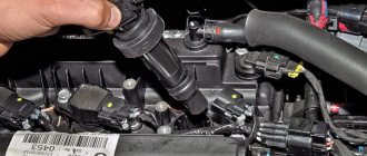
Ignition system
Breakdowns in the ignition system, namely malfunction of spark plugs, high-voltage wires and ignition coils, can lead to a tripping effect. So, you need to unscrew the spark plugs and inspect them for defects. Also, using a simple tester, measure the resistance of the high-voltage wires, which is 5 ohms.
Air supply
The formation of the air-fuel mixture is influenced by the state of the air supply. A clogged air filter element or throttle valve can cause a rich mixture, which can cause a tripping effect. To eliminate the malfunction, it is necessary to dismantle and inspect the elements.
If the air filter is clogged, it is recommended to replace it, but the throttle valve must be cleaned with a special product or liquid for cleaning carburetors.
Software problem
Repeatedly, the cause of the tripping and blinking “Check” is a malfunction of one of the sensors or accumulated errors inside the electronic engine control unit. So, it is necessary to diagnose the condition of the elements and replace damaged ones.
The movement of the car is accompanied by jerks or dips
Sharp or short-term jerks that appear while driving most often occur due to sparking failures. Due to the inertia of fuel combustion, short-term and sharp jerks due to a malfunction of the fuel system are not possible and the main attention should be focused on checking the spark plugs, high-voltage wires and the correct operation of the ignition coil. It is impossible to check the failure of sparking, breakdown of high-voltage wires and turn-to-turn short circuits on the ignition coil on your own, without the presence of diagnostic equipment. The problem can be solved by simply replacing known good parts of the ignition system.
What does a specialist see when looking for jerks made by a car while driving?
The processes of spark formation to ignite the fuel mixture in the cylinders occur at enormous speeds, in other words, these are fleeting processes and it is possible to record (“catch”) the point of loss of spark only with special devices, oscilloscopes, which can record information frame by frame after a given and very short period of time (in milliseconds and microseconds).
Normal spark burning
Defect - no spark
The left figure shows an oscillogram of a normally operating spark. From left to right - switching is turned on in the primary circuit of the ignition coil and a charge occurs, which, upon reaching time, releases the accumulated energy to the electrodes of the spark plug in the form of a high-voltage breakdown, which reaches 10.0 kilovolts. The breakdown instantly goes into spark mode (horizontal line), which operates at a voltage of 2.0 kilovolts. The spark burning section ends with wave-like damped oscillations, indicating the serviceability of the ignition coil (residual high-voltage voltage).
In the right figure, the oscillogram before the discharge breakdown is recorded in the same way by an oscilloscope, but then there is no horizontal section of the spark burning line. This is the jerk of the car in motion.
Jerking on a car with a UMP engine may also appear due to a malfunction of the synchronization sensors, while the emergency malfunction lamp on the instrument panel may not turn on. In this case, it is easier to replace the synchronization sensors.
Failure often occurs due to a malfunction of the ignition coil, which is independently determined by replacing a known-good coil or by a specialist using special diagnostic equipment.
ECU diagnostics
In order to understand which of the sensors or components affected the unstable operation of the engine, it is worth conducting a comprehensive diagnosis of the on-board computer. This requires an OBD II cable, a tablet and laptop, and software.
It is recommended to turn to professionals for help, who will quickly and efficiently perform diagnostic operations and fix the problem.
Deciphering error codes
If the car owner nevertheless decides to fix the problem on his own, then he will need to decipher the error codes that will appear on the diagnostic computer screen. So, let's look at all the error codes and their interpretation for the UMZ 4216 engine:
| DTC | Description |
| P0105 | Incorrect air pressure sensor signal |
| P0107 | Low signal level from air pressure sensor |
| P0108 | High signal level from the air pressure sensor, |
| P0122 | Low signal level from throttle position sensor (1 track) |
| P0123 | High signal level from the throttle position sensor (1 track) |
| P0112 | Low signal level from air temperature sensor |
| P0113 | High signal level from the air temperature sensor |
| P0115 | Incorrect signal from the coolant temperature sensor |
| P0117 | Low signal level from the coolant temperature sensor |
| P0118 | High signal level from the coolant temperature sensor |
| P0130 | No activity of oxygen sensor No. 1 |
| P0131 | Low signal level from oxygen sensor No. 1 |
| P0132 | High signal level from oxygen sensor No. 1 |
| P0133 | Oxygen Sensor #1 - Slow Response |
| P0135 | Open circuit of oxygen sensor heater No. 1 |
| No. 1 oxygen sensor heater circuit short to ground | |
| Short to power in the oxygen sensor heater circuit No. 1 | |
| P0137 | Low signal level from oxygen sensor No. 2 |
| P0138 | High signal level from oxygen sensor No. 2 |
| P0141 | Open circuit of oxygen sensor heater No. 2 |
| Short to ground circuit of the heater of the oxygen sensor Lg "2 | |
| Short to power in the oxygen sensor heater circuit No. 2 | |
| P0201 | Broken injector of cylinder 1 |
| Ground fault in cylinder 1 injector | |
| Short circuit to power supply of injector 1 cylinder | |
| P0202 | Broken injector of cylinder 2 |
| Injector 2 cylinder short to ground | |
| Short circuit to power supply of injector 2 cylinders | |
| P0203 | Broken injector cylinder 3 |
| Injector 3 cylinder ground short | |
| Short circuit to power supply of injector 3 cylinders | |
| P0204 | Broken injector 4 cylinders |
| Injector 4 cylinder ground short | |
| Short circuit to power injector 4 cylinders | |
| P0217 | Engine temperature is above the maximum permissible |
| P0219 | Engine speed is above the maximum permissible |
| P0221 | Range limit of the difference between 1 and 2 tracks of TPS |
| P0222 | Low signal level from throttle position sensor (2 track) j |
| P0223 | High signal level from the throttle position sensor (2 track) j |
| Open circuit of the fuel relay | |
| P0230 | Fuel relay primary circuit short to ground |
| Fuel relay primary circuit short to power | |
| P0301 | Misfire in cylinder 1 |
| P0302 | Misfire in cylinder 2 |
| P0303 | Misfire in cylinder 3 |
| P0304 | Misfire in cylinder 4 |
| P0327 | Low signal level from knock sensor |
| P0339 | HF Sync Sensor Synchronization Error |
| P0335 | HF synchronization sensor break |
| P0341 | Phase sensor synchronization error |
| P0351 | Broken ignition coil 1 |
| P0352 | Broken ignition coil 2 |
| P0420 | Low efficiency of the exhaust catalyst |
| Open circuit of the canister purge valve | |
| P0443 | Short circuit to ground in the canister purge valve circuit |
| Short circuit to power in the canister purge valve circuit | |
| Cooling fan relay primary circuit open | |
| P0480 | Cooling fan relay primary circuit short to ground |
| Cooling fan relay primary circuit short to power | |
| P0501 | Broken vehicle speed sensor |
| • | Idle air control malfunction | |
| P0505 | Open circuit of the idle speed regulator |
| Idle air control circuit short to power | |
| P0563 | High on-board voltage |
| P0562 | Low on-board voltage |
| P0603 | Control unit EEPROM error |
| P0604 | Control unit external RAM error |
| P0605 | Error in the external ROM of the control unit (ROM1) |
| P0606 | Control unit initialization error |
| Open circuit of the CHECK ENGINE lamp | |
| P0650 | Short circuit to ground in the CHECK ENGINE lamp circuit |
| Short to power in the CHECK ENGINE lamp circuit | |
| P1107 | Low signal level from the barocorrection sensor |
| P1108 | High signal level from the barocorrection sensor |
| P1122 | Low signal level from the accelerator pedal position sensor (1 track) |
Design features of the UMZ injection engine
The camshaft is connected to the crankshaft through a gear made of textolite or fluoroplastic. A metal washer is pressed into the gear rim; when it passes by the phase sensor, the position of the camshaft is recorded and a signal about this is sent to the control unit. Camshaft with lower location. The transmission of movements to the valves located in the upper part of the block head is carried out through durable rods made of aluminum alloy. The rods, which are in contact with the camshaft cams at the bottom and the rocker arms at the top, transmit movement to the valve stems, strictly in accordance with the profile of the cams and their angular locations.
The working part of the rocker arm is its profiled section, which, resting against the end of the valve stem, controls its opening and closing. The thermal gap between the working part of the rocker arm and the end of the valve is provided by an adjusting bolt or installed hydraulic compensators. Adjustment of thermal clearances is carried out on a cold engine with a temperature of no lower than 20 degrees and no higher than 30. Adjustment of the position of hydraulic compensators is also carried out in the range of these temperatures, and the adjustment procedure is similar to the regulation procedure without hydraulic compensators.
Conclusion
Determining why the “Check Engine” blinks on a Gazelle Business with a UMZ 4216 engine and tripping appears is quite simple. To do this, it is worth carrying out a comprehensive diagnosis of the electronic control unit and deciphering the error codes. If this does not give anything, then the problem should be looked for in the formation of the air-fuel mixture or the ignition system.
Reviews. Auto News. Test drives
Main Menu
- Home
- P0105 OBD-II Error: Manifold Atmospheric Pressure (MAP) Sensor Malfunction
Difficulty starting the UMZ engine when cold
The issue of cold starting is problematic both for specialists and for the car owner. This situation arises due to the fact that the car arrives for diagnostics with a hot engine, and when it is hot it starts just fine. The owner cannot check a cold engine on his own due to the lack of diagnostic equipment.
However, there are a number of important reasons why the UMP engine is difficult to start when cold:
It should be noted that experts identify some of the listed defects on a hot engine, but even after they are eliminated, the question remains open until the next time the engine is started on a cold one.
P0105 OBD-II Error: Manifold Atmospheric Pressure (MAP) Sensor Malfunction
The MAP sensor is an integral part of the fuel injection system and provides information to the engine control unit (ECU) to ensure smooth engine operation and good fuel economy.
A MAP pressure sensor problem can have several causes:
- the output voltage of the sensor readings is outside the range of input parameters of the control unit;
- The most common problem is that the vacuum hose on the sensor may be broken, damaged or kinked;
- The sensor wiring may be bad, brittle, or have poor connections. It may also be located close to high voltage components, especially generators, ignition wires, etc.
- The sensor may get stuck in one position.
- problems in the fuel system or piston group. If the vehicle's fuel system has low pressure or a burnt valve, these faults prevent the MAP sensor from receiving the correct value.
Symptoms of the error
The "Check Engine" light on the dashboard comes on. Most often the car does not work normally. It idles unsteadily and accelerates randomly. This is all because the MAP sensor and throttle position sensor are not working in sync.
Diagnosis of DTC P0105
First the P0105 should be cleared from memory and rechecked to see if it returns. If the error reappears, a visual inspection must be performed to ensure that the vacuum lines and other hoses on the intake system are intact and in place. If everything is in place and there is no damage, you need to check the voltage at the sensor with the engine running to determine whether the voltage reading changes with engine speed.
How serious is the error?
DTC P0105 causes the engine to malfunction and requires immediate attention. It is extremely important that it is resolved as quickly as possible. The problem of the pressure sensor leads to excessive fuel consumption and unstable engine operation. Often, after resetting the error by the scanner, the car will work normally and the error will not return.
What needs to be repaired?
Vacuum lines and electrical connector and wiring. Disconnect/connect electrical connectors to ensure fresh contact. Check hoses for cracks and kinks, especially on older cars. If no problems are found, replace the MAP sensor.
Owners of Mercedes, Mitsubishi, and Opel cars often complain about the DTC p0105 error.
All errors GAZ 3110 (Volga), GAZ 31105 (Volga), VOLGA SIBER, GAZELLE (3302, 33023, 2705, 2217, 2752, 3221, 32213, 322132, BUSINESS, SOBOL, VALDAI), GAZELLE NEXT
Recommendations for long-term operation of the UMP engine without repair
Unlike the ZMZ-405 engine, the 16-valve UMZ-4216 (and similar series) works flawlessly, is durable and resistant to operation on gas (propane, methane). Of course, after continuing the modernization and installation of hydraulic compensators, the engine often began to ask specialists for diagnostics. Hydraulic compensators installed on the gas distribution mechanism rods are the only weak link of this engine, but this can be easily solved by replacing the rods and adjusting bolts without hydraulic compensators.
Otherwise, if the maintenance requirements are met, the motor will operate stably and with proper dynamic performance.
Timely adjustment of the thermal clearances of the valves, cleaning the air path of the throttle assembly, chemically washing the injectors with simultaneous decarbonization of the CPG, periodic maintenance of the fuel tank with a moisture displacer (isopropyl, medical, technical alcohol), replacing all filters included in the package - this is the key to the successful operation of a commercial vehicle. transport.
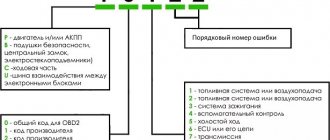
GAS errors via OBDI protocol. Self-diagnosis.
012 — The unit’s self-diagnosis mode is turned on (short circuit of the L-line to ground). 013 - Low signal level of the mass air flow sensor (MAF). 014 - High signal level of the mass air flow sensor (MAF). 015 - Low signal level of the absolute air pressure sensor (DAP). 016 - High signal level of the absolute air pressure sensor (DAP). 017 — Low signal level of the air temperature sensor (DTV). 018 - High signal level of the air temperature sensor (DTV). 019 - Engine overheating (coolant temperature above 105°C). 021 - Low signal level of the coolant temperature sensor (DTOZH). 022 - High signal level of the coolant temperature sensor (DTOZH). 023 - Low signal level of the throttle position sensor (TPS). 024 - High signal level of the throttle position sensor (TPS). 025 - Low voltage level in the on-board network. 026 - High voltage level in the on-board network. 027 - Only for MIKAS: Malfunction of the DPKV or secondary ignition circuits. 027 - Only for AUTRON: Incorrect initial setting of the throttle position sensor (TPS). 028 - Only for MIKAS: Malfunction of the DPKV or secondary ignition circuits. 028 - Only for AUTRON: The crankshaft speed has exceeded the maximum. 029 - Only for MIKAS: Malfunction of the DPKV or secondary ignition circuits. 029 - Only for AUTRON: Incorrect connection of the crankshaft speed sensor. 031 — Low signal level of the (first) CO corrector. 032 — High signal level of the (first) CO corrector. 033 - Low signal level of the second CO corrector. 034 - High signal level of the second CO corrector. 035 - Low signal level of the main (first) lambda probe (oxygen sensor). 036 - High signal level of the main (first) lambda probe (oxygen sensor). 037 - Low signal level of the additional (second) lambda probe (oxygen sensor). 038 - High signal level of the additional (second) lambda probe (oxygen sensor). 041 - Malfunction of the (first) knock sensor (DS) circuit. 042 - Malfunction of the second knock sensor (DS) circuit. 043 - Low signal level of the recirculation valve position sensor. 044 - High signal level of the recirculation valve position sensor. 045 - Low signal level of the canister valve position sensor. 046 - High signal level of the canister valve position sensor. 047 - Low signal level of the power steering sensor (power steering). 048 - High signal level of the power steering sensor (power steering). 051 - Malfunction of 1 control unit. 052 - Malfunction of control unit 2. 053 - Malfunction of the crankshaft position sensor (CPS). 054 - Malfunction of the camshaft position sensor (DPRV). 055 - Malfunction of the vehicle speed sensor (VS). 056 - Short circuit of the ignition coil circuit of cylinders 1/4 (for AUTRON units). 057 - Short circuit of the ignition coil circuit of cylinders 2/3 (for AUTRON units). 058 — Open circuit of the crankshaft position sensor (for AUTRON units). 061 - Reset the control unit in working condition. 062 - Malfunction of the control unit's random access memory (RAM). 063 - Malfunction of the control unit's permanent memory (ROM). 064 - Malfunction when reading the flash RAM of the control unit (EEPROM). 065 - Malfunction when writing to the flash RAM of the control unit (EEPROM). 066 - Malfunction when reading the control unit identification code. 067 - Malfunction of 1 immobilizer. 068 - Malfunction of immobilizer 2. 069 - Malfunction of immobilizer 3. 071 - Low idle speed. 072 - High idle speed. 073 - Rich mixture signal from lambda probe 1 at maximum leanness. 074 - Lean mixture signal from lambda probe 1 at maximum enrichment. 075 - Rich mixture signal from lambda probe 2 at maximum leanness. 076 - Lean mixture signal from lambda probe 2 at maximum enrichment. 079 — Malfunction when adjusting the recirculation valve using the sensor. 081 — Maximum displacement of the ignition timing angle (IAF) by detonation in cylinder 1. 082 — Maximum displacement of the ignition timing angle (IAF) by detonation in cylinder 2. 083 — Maximum displacement of the ignition timing angle (IAF) by detonation in cylinder 3. 084 — Maximum displacement of the ignition timing angle (IAF) by detonation in cylinder 4. 085 - Maximum displacement of the ignition timing angle (IAF) by detonation in cylinder 5. 086 - Maximum displacement of the ignition timing angle (IAF) by detonation in cylinder 6. 087 - Maximum displacement ignition timing (IAF) for detonation in cylinder 7. 088 - Maximum displacement of the ignition timing (IAF) for detonation in cylinder 8. 091 - Short circuit to the on-board network in ignition circuit 1. 092 - Short circuit to the on-board network in ignition circuit 2. 093 - Short circuit to the on-board network in ignition circuit 3. 094 - Short circuit to the on-board network in ignition circuit 4. 095 - Short circuit to the on-board network in ignition circuit 5. 096 - Short circuit to the on-board network in ignition circuit 6. 097 - Short circuit to the on-board network in ignition circuit 7. 098 - Short circuit to the on-board network in circuit 8 of the ignition. 099 - Malfunction of the high voltage driver. 131 - Short circuit to the circuit board of injector 1. 132 - Open circuit or short to ground of the injector circuit 1. 133 - Short circuit to ground of the injector circuit 1. 134 - Short circuit to the circuit board of the injector 2 135 - Open circuit or short circuit to ground of the injector circuit 2. 136 — Short circuit to ground of the injector circuit 2. 137 — Short circuit to the electrical system of the injector circuit 3. 138 — Open circuit or short circuit to ground of the injector circuit 3. 139 — Short circuit to ground of the injector circuit 3. 141 — Short circuit to the electrical system of the circuit injector 4. 142 - Open circuit or short to ground in the injector 4 circuit. 143 - Short circuit to ground in the injector 4 circuit. 144 - Short circuit to the on-board network of the injector 5 145 - Open circuit or short to ground in the injector 5 circuit. 146 - Short circuit to ground of injector circuit 5. 147 - Short circuit to ground circuit of injector circuit 6. 148 - Open circuit or short circuit to ground of injector circuit 6. 149 - Short circuit to ground of injector circuit 6. 151 - Short circuit to ground circuit of injector circuit 7. 152 - Open circuit or short circuit to ground of the injector circuit 7. 153 - Short circuit to ground of the injector circuit 7. 154 - Short circuit to the on-board network of the injector circuit 8. 155 - Open circuit or short circuit to ground of the injector circuit 8. 156 - Short circuit to ground of the injector circuit 8. 157 - Short circuit to the on-board network of the starting injector circuit. 158 - Open or short to ground in the starting injector circuit. 159 - Short circuit to ground in the starting injector circuit. 161 - Short circuit to the on-board network of control circuit 1 of the additional air regulator (RDV or IAC). 162 - Open circuit or short to ground in control circuit 1 of the additional air regulator (RDV or IAC). 163 - Short circuit to ground in control circuit 1 of the additional air regulator (RDV or IAC). 164 - Short circuit to the on-board network of control circuit 2 of the additional air regulator (RDV or IAC). 165 - Open circuit or short to ground in control circuit 2 of the additional air regulator (RDV or IAC). 166 - Short circuit to ground in control circuit 2 of the additional air regulator (RDV or IAC). 167 - Short circuit to the on-board network of the electric fuel pump relay circuit. 168 — Open circuit or short to ground in the electric fuel pump relay circuit. 169 - Short circuit to ground in the electric fuel pump relay circuit. 171 - Short circuit to the on-board network of the recirculation valve circuit. 172 - Open circuit or short to ground in the recirculation valve circuit. 173 - Short circuit to ground in the recirculation valve circuit. 174 - Short circuit to the on-board network of the canister valve circuit. 175 - Open circuit or short to ground in the canister valve circuit. 176 - Short circuit to ground in the canister valve circuit. 177 — Short circuit to the main relay circuit on-board. 178 — Open circuit or short to ground in the main relay circuit. 179 - Short circuit to ground in the main relay circuit. 181 - Short circuit to the on-board network of the malfunction lamp circuit (Check Engine). 182 - Open circuit or short to ground in the fault lamp circuit (Check Engine). 183 - Short circuit to ground in the fault lamp circuit (Check Engine). 184 - Short circuit to the tachometer circuit. 185 - Open or short to ground tachometer circuit. 186 - Short circuit to ground in the tachometer circuit. 187 - Short circuit to the on-board network of the fuel flow meter circuit. 188 — Open or short to ground in the fuel flow meter circuit. 189 - Short circuit to ground in the fuel flow meter circuit. 191 - Short circuit to the on-board network of the air conditioner relay circuit. 192 - Open or short to ground in the air conditioner relay circuit. 193 - Short circuit to ground in the air conditioning relay circuit. 194 — Short circuit to the on-board network of the cooling fan relay circuit. 195 — Open or short to ground in the cooling fan relay circuit. 196 - Short circuit to ground in the cooling fan relay circuit. 197 - Short circuit to the on-board network of the EPHH valve circuit. 198 — Open circuit or short to ground in the EPH valve circuit. 199 — Short circuit to ground in the EPH valve circuit. 231 - Open circuit or short to ground in ignition circuit 1. 232 - Open circuit or short to ground in ignition circuit 2. 233 - Open circuit or short to ground in ignition circuit 3. 234 - Open circuit or short to ground in ignition circuit 4. 235 - Open circuit or short to ground in ignition circuit 5. 236 - Open circuit or short to ground in ignition circuit 6. 237 - Open circuit or short to ground in ignition circuit 7. 238 - Open circuit or short to ground in ignition circuit 8. 241 - Short circuit to ground in ignition circuit 1. 242 - Short circuit to ground in ignition circuit 2. 243 - Short circuit to ground in ignition circuit 3. 244 - Short circuit to ground in ignition circuit 4. 245 - Short circuit to ground in ignition circuit 5. 246 - Short circuit to ground in ignition circuit 6. 247 - Short circuit to ground in ignition circuit 7. 248 - Short circuit to ground in ignition circuit 8. 251 — Short circuit to the on-board network of the mass air flow sensor burning circuit. 252 — Open or short to ground in the burning circuit of the mass air flow sensor. 253 - Short circuit to ground in the burning circuit of the mass air flow sensor.
Fault Codes Engine 405 24 Euro 3
codes for Mikas 5.4 Description of faults
12 Diagnostic Circuit Performance 13 Air Flow Sensor Low 14 Air Flow Sensor High 17 Air Temperature Sensor Low 18 Air Temperature Sensor High 21 Coolant Temperature Sensor Low 22 Coolant Temperature Sensor High 23 Low signal level of the throttle position sensor 24 High signal level of the throttle position sensor 25 Low voltage level of the vehicle's on-board network
26 High voltage level of the vehicle's on-board network
31 Low signal level of the CO potentiometer 32 High level of the signal of the CO potentiometer 51 Malfunction of the control unit 1 52 Malfunction of the control unit 2 53 Malfunction of the angular synchronization sensor 54 Malfunction of the camshaft position sensor 61 Unauthorized restart of the control unit 62 Loss of information in the RAM of the control unit 63 Malfunction of the permanent memory 64 Malfunction when reading the non-volatile memory of the control unit 65 Malfunction when writing to the non-volatile memory of the control unit 131 Malfunction of injector 1 (short circuit) 132 Malfunction of injector 1 (break) 133 Malfunction of injector 1 (short circuit to ground) 134 Malfunction of injector 2 (short circuit) ) 135 Faulty injector 2 (open) 136 Faulty injector 2 (short circuit to ground) 137 Faulty injector 3 (short circuit) 138 Faulty injector 3 (open circuit) 139 Faulty injector 3 (short circuit to ground) 141 Faulty injector 4 (short circuit) chanting) 142 Faulty injector 4 (open) 143 Faulty injector 4 (short circuit to ground) 161 Faulty winding 1 RDV (short circuit) 162 Faulty winding 1 RDV (break) 163 Faulty winding 1 RDV (short circuit to ground) 164 Faulty winding 2 RDV ( short circuit) 165 Malfunction of winding 2 RDV (open) 166 Malfunction of winding 2 RDV (short circuit to ground) 167 Malfunction of the fuel pump relay circuit (short circuit) 168 Malfunction of the fuel pump relay circuit (open) 177 Malfunction of the main relay circuit (short circuit) 178 Failure rightness Main relay circuit (open) 181 Diagnostic lamp circuit malfunction (short circuit) 182 Diagnostic lamp circuit malfunction (open) Fault codes can be read from memory in the fault code display mode. This mode is activated if, with the ignition on and the engine stopped, contacts 10 and 12 of the diagnostic connector located under the hood of the vehicle are closed. When fault codes are displayed using ON/OFF. The diagnostic lamps display: a sign of serviceability of the diagnostic circuit (code 12) and fault codes. Each code is displayed three times in a row.
Lamp activation mode for each code:
the number of activations corresponding to the first digit of the code is a pause; the number of activations corresponding to the second digit of the code is a pause; the number of activations corresponding to the third digit of the code is a long pause; – repeat the code or output a new code. If there are no fault codes in the memory, then code 12 continues to be displayed. If code 12 is missing, you must use the description of the diagnostics on card A - “Checking the diagnostic circuit”.
Removing fault codes from memory:
Fault codes stored in the memory can be deleted by removing the battery ground terminal for more than 10 seconds. It is necessary to ensure that the ignition is turned off to avoid damage to the electronic unit. In addition, code 62 - RAM error - will be stored in the list of one-time faults for some time.
Information for the article was taken from the website: https://remontgruzovik.ucoz.ru
Only registered and authorized users can leave comments.
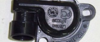
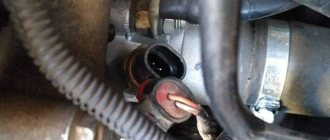
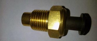
Replacing the camshaft sensor
The sensor is attached to the housing with a single bolt. Usually it has a 10mm head. To unscrew it you need a socket wrench. First, you need to remove the chip from the DPRV. Once you have removed the bolt, gently pull the sensor up to remove it from its seat.
Assembly occurs in reverse order. The sensor seat is sealed with a rubber ring. Also note that the installation gap between its end and the upper edge of the marking pin should be within 0.5...1.2 mm. The sensor is installed in place, secured with a bolt and the chip is connected.
The process of replacing the DPRV on a Lada car
Experts recommend replacing the sensor every 100 thousand kilometers or every 5 years (whichever comes first). This recommendation is due to the fact that the sensor operates in a constantly changing temperature regime. In this regard, a temperature difference occurs in the semiconductor filling of the sensor, which really “dislikes” this.
The electronics that control the operation of a modern car engine receive information from a group of meters that record air flow, temperature, exhaust gas composition, and so on. In the latest generation of cars, the number of measuring elements has increased - an electromagnetic camshaft position sensor (abbreviated as DPRV) has appeared. Car enthusiasts who prefer to diagnose malfunctions on their own should familiarize themselves with the symptoms of malfunctions of the specified device and how to check it.
What to check
Often replacing the sensor will correct this code, but this does not always help. Therefore it is important to check the following:
- Make sure the wiring is not routed too close to any secondary ignition components (coil, spark plug wires, etc.).
- Visually check the camshaft sensor wiring for signs of burns, discoloration, indicating overheating or chafing.
- Visually check the DPRV for damage.
- Visually check the timing belt pulley through the sensor hole (if possible) for missing teeth or any damage.
- If the drive disc is not visible from the outside of the engine, a visual test can only be performed by removing the camshaft or intake manifold (depending on engine design).
- If everything is in order, replace the sensor.
Definition of error P0341 means error P0341 occurrence of error P0341 symptoms of error P0341 diagnoses error P0341 General errors appears error P0341 correct error P0341 eliminating error P0341 Definition of error P0341 diagnosing code P0341 general error code Saving error code this error code and error codes Clear error codes diagnosing code P0341 general error code Saving error code this error code and error codes Clear error codes diagnosing code P0341 this error codewith error codereset error code
cases fixes the value of mikas bank used definition is carried out
The engine stalls, the check light flashes or lights up: the main reasons
Let's start with the fact that injection engines are equipped with special catalyst devices for cleaning the exhaust. At the same time, the catalytic converter is a rather vulnerable and at the same time expensive element, and all sorts of malfunctions in the engine create a risk of damage.
As a rule, the check flashes when there is a risk of damage to the catalyst. In this case, the simultaneous tripping of the engine means that one or more cylinders are not working or are not working correctly. In practice, this means that the fuel in the problem cylinder does not burn completely, after which it enters the exhaust system.
As a result, the remaining unburnt fuel burns out in the area where the catalyst is located, since the temperatures there are very high. Fuel also gets on the catalyst itself, causing it to fail.
It should be added that the check also often lights up in the event of failure of any ECM sensors. One way or another, it is quite obvious that the “check” in the vast majority of cases indicates either problems with the electronic engine control system itself, or the risk of damage to the catalyst due to malfunctions of the internal combustion engine.
It is important to understand that the engine tripping indicates a non-functioning cylinder. In this case, the check is flashing not due to the failure of any ECM sensor, malfunction of the exhaust gas recirculation system or poor fuel in the tank, but rather signals to the driver about a direct threat to the catalyst.
In a nutshell, fuel that is not burned and gets into the outlet causes a special sensor (lambda probe, oxygen sensor) to send readings to the ECU indicating deviations from the norm. The control unit begins to try to correct the situation, but taking into account the tripping, it is simply not able to adjust the operation of the motor so that everything returns to normal. As a result, fuel consumption increases, while the engine operates unstably, idle speed fluctuates, etc. In some cases, the engine “falls” into emergency mode.
This feature of engine operation is primarily aimed at preventing burnout or melting of the catalyst. The catalyst itself consists of small honeycomb cells. If unburned fuel intensively enters the exhaust and burns out in the catalyst, the element will simply melt.
This melting will lead to the fact that exhaust gases will not be able to pass normally through the catalyst, that is, a plug appears in the exhaust pipe. Naturally, the engine will “suffocate”, power will drop, the engine may not start at all, etc.
Also, the catalyst will no longer be able to clean the exhaust, and toxicity will increase. There is only one way out in this situation - repairing the engine to eliminate the main cause of the engine tripping, and only then replacing the expensive catalyst with a new one. To minimize risks, a special program is programmed into the ECU, which involves operating the engine in emergency mode.