How to replace the front brake cylinder on a classic
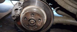
- Remove the wheel and hang the hub
We turn the wheel to the left if we change the cylinders on the right caliper, if on the left, then to the right. Don't forget about safety measures - put stops or a stump under the lever of the suspended wheel - this will protect you from the car falling off the jack.
- Use a pry bar or pliers to separate the brake pads
This is necessary to easily remove the pads from the caliper, otherwise you will not be able to remove them.
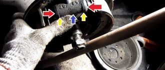
- We unsplint the guides and knock them out of the brake cylinders with a hammer.
- We take out the brackets and pads. How to do this correctly and the points described above are described in detail in the article Replacing the front brake pads of a VAZ 2016. In order to avoid making mistakes, I recommend that you read this lesson.
- In order not to lose a lot of brake fluid, remove the cap from the reservoir, put a bag over the neck and screw the cap into place. Thus, the cover will be sealed and will not allow all the liquid to drain when removing the hose from the front brake cylinder of the VAZ 2107.
Or we pinch the brake hose so as not to lose the entire “brake housing” when unscrewing it from the caliper. In this case, there is a high probability of running into replacing the hose. It dries out over time and when it is forcibly compressed, it can begin to leak.
- Using wrenches or a socket “14” we unscrew the brake hose fastenings
- Using a “17” wrench, unscrew the two fastening bolts and remove the brake caliper from the hub
- We clamp the caliper in a vice, use special wrenches to unscrew the tube
To do this, we put a split wrench on “10” onto the nut securing the brake pipe. If necessary, you can lightly tap it with a hammer so that it is more securely fixed on the edges of the nut. We clamp this key with a screw, thereby its walls tightly compress the nut, and tear it off. This is the only way you will not “lick” the edges of this nut.
After you “tear off” the nut, you can unscrew it with a regular open-end wrench. We do this carefully, making sure that the brake pipe does not rotate together with the nut, it may break.
It is recommended to unscrew the nut several times by half a turn and tighten it to move the area where the nut meets the tube apart. After this, we move it to the side, without breaking it too much, making sure that a crack does not form at the break point.
- We clamp the clamp and knock out the old brake cylinder from its seat
It is necessary to fix the clamp so that it does not interfere with knocking the cylinder out of the caliper. Try to save it, since it may not be included with the new brake cylinder. If you can’t fix it, you need to pull it out, no, with one hand we press on it with a sharp, thin object (a nail), with the other, we carefully knock out the cylinder with a hammer.
It is recommended to do this through a soft metal guide, but there may not be a third hand, so first we tap with a hammer so that the place where the latch is located moves and it hides in the depths of the guide. Then with the freed hand we hold the attachment and completely knock out the old part from the caliper.
- We clean the seat for the new brake cylinder.
It “walks” on a slide on which dirt and rust can accumulate. To avoid problems with installing a new part, you need to clean them.
- We remove the old retainer from the cylinder to install it on the new one.
If this is not possible, then we buy new ones for the brake calipers or make them ourselves. An object made of durable material, such as a nail, with a diameter corresponding to the diameter of the mounting hole in the cylinder, is suitable for this.
Important! When making such clamps yourself, it is worth considering that when you subsequently replace the cylinder, it will no longer be possible to “sink” it into the body, because there are no springs. Secondly, you need to accurately measure the depth of the seat and make the length of the homemade product a little longer by 1.5-2 mm. This is due to the fact that the next time you change the cylinder, you will have to knock it out by force, cutting off this retainer, due to the lack of a spring in it, since it will no longer be possible to pull it out. The longer it is, the harder it is to cut it, and you can damage the caliper body.
- Lubricate the cylinder slide with a thin layer of oil or lithol so that it slides better in the caliper. Using the adapter, we drive the new part into its seat until the hole for the clamp aligns with the slot in the caliper body. We insert the manufactured clamp and lightly knock the cylinder until it stops so that it is fixed with it.
- Screw on the brake pipe.
The main thing in order to “get” into the thread is to correctly align the tube nut and the hole for it. If, when tightening the nut, you feel that it is too tight to turn - you have not “got it”, it is better to remove the nut and re-align it with the thread of the hole. There is no need to tighten too much. After installing the caliper on the car and bleeding the system, if fluid leaks in this place, then tighten it with an open-end wrench.
Installation on the car occurs in the reverse order.
Video of replacing the VAZ front brake cylinder:
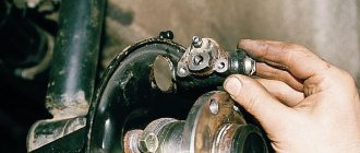
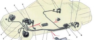
Location and purpose of the GTZ
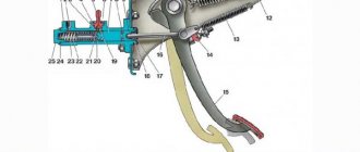
The master cylinder is an oblong cylinder with sockets for connecting brake circuit pipes. The element is located in the rear of the engine compartment, opposite the driver's seat. The GTZ is easy to detect by a two-section expansion tank installed above the unit and connected to it by 2 hoses.
The cylinder is secured with two M8 nuts to the flange of the vacuum brake booster. These components work in pairs - the rod coming from the pedal presses on the GTZ pistons, and the vacuum membrane enhances this pressure, making the driver’s work easier. The cylinder itself performs the following functions:
- distributes fluid over 3 working circuits - two serve the front wheels separately, the third - a pair of rear ones;
- through fluid, it transmits the force of the brake pedal to the working cylinders (RC), which compress or expand the pads on the wheel hubs;
- directs excess fluid to the expansion tank;
- returns the rod and pedal to their original position after the driver stops pressing it.
Malfunctions and methods for diagnosing a hydraulic cylinder
Checking the brake system in general and the GTZ in particular is performed when characteristic signs appear:
- the red lamp for insufficient brake fluid level came on on the instrument panel;
- the free play of the pedal has increased greatly or it openly fails;
- to slow down the car you have to press the pedal hard;
- uneven braking - the car pulls to the side when pressed sharply;
- the vehicle slows down with difficulty, the pedal presses to the floor.
Design and principle of operation of the unit
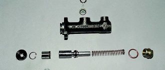
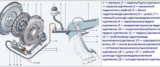
At first glance, the design of the master cylinder seems complex, since it consists of many small parts. A diagram and list of these elements will help you understand the device (the positions in the picture and in the list are the same):
- Die-cast metal housing for 2 working chambers.
- The washer is a retainer for the bypass fitting.
- A discharge fitting connected by a hose to the expansion tank.
- Sealing gasket of the fitting.
- Limit screw washer.
- The screw is a piston movement limiter.
- Return spring.
- Support cup.
- Compensation spring.
- Ring sealing the gap between the piston and the body - 4 pcs.
- Spacer ring.
- Piston servicing the circuit of the rear wheels;
- Intermediate washer.
- A piston operating on 2 circuits of the front wheels.
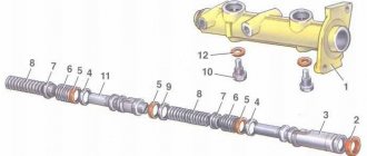
Since there are 2 chambers in the GTZ housing, each has a separate bypass fitting (item 3) and a limit screw (item 6).
At one end the cylinder body is closed with a metal plug, at the second there is a connecting flange. At the top of each chamber there are channels for connecting system pipes (screwed on threads) and discharging liquid into the expansion tank through fittings and pipes. Sealing collars (item 10) are installed in the piston grooves.
The GTZ operating algorithm looks like this:
- Initially, return springs hold the pistons near the front walls of the chambers. Moreover, the spacer rings rest against the limiting screws, the liquid from the tank fills the chambers through open channels.
- The driver presses the brake pedal and selects free play (3-6 mm), the pusher moves the first piston, the cuff closes the channel of the expansion tank.
- The working stroke begins - the front piston squeezes the liquid into the tubes and forces the second piston to move. The fluid pressure in all pipes increases equally, and the brake pads of the front and rear wheels are activated simultaneously.
When the driver releases the pedal, the springs return the pistons to their original position. If the pressure in the system rises above normal, some of the liquid will flow through the channels into the tank.
An increase in pressure to a critical level often occurs due to boiling of the liquid. While on a trip, an acquaintance of mine added counterfeit DOT 4 to the expansion tank of the “Seven”, which subsequently boiled. The result is partial brake failure and urgent repairs.