01/25/2022 1,609 Alarms
Author: Victor
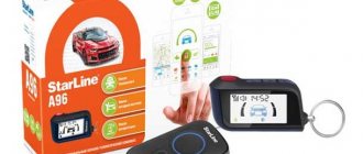
The Starline A61 alarm system provides extensive functionality, including notification and feedback options. Thanks to them, the car owner can use the security system and learn about its status remotely.
[Hide]
Specifications
Description of the main characteristics:
- sending data between them is carried out via radio channels operating at a frequency of 433.05–434.79 MHz;
- the range of action of the communicator when operating in signal transmission mode will be about 800 m;
- receiving signals from the control unit is possible within a radius of up to 2000 m;
- the number of radio channels used to transmit signals is 128, but data is sent over one or more;
- The range of the additional key fob is 15 m;
- the operation of protection zones is ensured by a shock and sensitivity sensor of the piezoelectric type;
- the use of the anti-theft system is allowed in the temperature range from –40 to +85 degrees;
- to power the security system, 9–18 volts of voltage will be required, so using an alarm system on heavy trucks with a 24-volt network is impossible;
- when the protection mode is turned on, the current consumption of the anti-theft system should be no more than 15 mA;
- when security is activated, the siren requires a power supply of no more than 2 A;
- at the output of the external power line to block the engine, the current level will be up to 200 mA;
- dialogue code technology is used to protect signals;
- The main communicator is powered from a single AAA class source rated at 1.5 V;
- The replacement key fob uses one 3V CR2450 battery.
The range of the Starline A61 alarm communicator depends on weather conditions and local developments.
The channel “Crossover 159” spoke briefly about the configuration, as well as the technical characteristics of the car alarm.
Understanding the names
The A61 model is, by definition, interactive. Sometimes, to emphasize this fact, the word Dialog is added to the name. This is what the creators of the official website did, for example:
And Starline Twage A61 is an old version of the name. It is still found in some catalogs and is associated with models that do not have dialogue code. For example, there are two different alarms: Twage B9 and B9 Dialog. They have different additional keychains:
The above does not apply to the A61 family - there is only one model that is equipped with “dialogue”. The strangest version of the name used to designate it looks like this: Starline Twage A61 Dialog. Here is a screenshot as proof:
We will talk about connecting this signaling now.
Main features of the system
List of features of the Starline A61 car alarm:
- the presence of the “Turbo timer” function, intended for cars with diesel and turbocharged units;
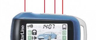
- displaying the alarm status on the key fob display;
- the ability to change the sensitivity level of the shock controller;
- the presence of an option for silent activation of security, as well as setting the car to security without sound;
- automatic arming if the alarm is accidentally turned off;
- the ability to activate the protection mode on a car with the engine running;
- option to disable security without using a communicator;
- the presence of a central locking control function: using the remote control or from the ignition when the car is moving;
- the possibility of additional installation and use of a GSM module, which allows you to determine the coordinates of the vehicle;
- the presence of the “Comfort” option for keyless alarm control, as well as automatic closing of electric windows;
- the “Panic” function, which allows you to activate the car lights and siren to search for a car in the parking lot;
- the ability to remotely configure the operation of the communicator, as well as car alarm modes;
- the presence of the “Valet” function, with which you can control the security system in emergency mode;
- two-stage opening of door locks;
- The car owner is notified of problems in sound and vibration modes.
Excerpts from the Starline manual
Our review would not be complete if it did not include excerpts from the basic instructions. Included with the alarm you can find two books:
- The operating instructions contain a table of basic settings, as well as a sequence that allows you to register key fobs;
- The installation manual provides all the diagrams, as well as the missing algorithms: the method of programming the system and the method of resetting to the “factory settings”.
See what the settings table looks like:
This table is printed in each of the two manuals: operating and installation manuals.
Settings can be accessed by following certain steps. You will find their sequence in the installation instructions:
- With the ignition turned off, press the Valet button 5 times;
- The ignition is turned on, the siren sounds 5 times;
- By pressing the Valet button, select one of the options;
- To set a new value, press the corresponding key on the key fob.
There is nothing complicated here. The interval between steps should be less than 10 seconds.
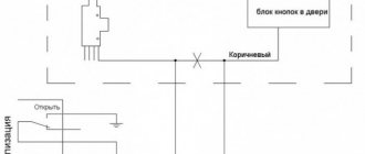
The connection diagram of the main connector should also be considered:
The instructions forgot to say the following: when connecting not one, but several wires to the “door input”, you need to use diodes. For a negative polarity input, the cathode will “look” towards the buttons. Be guided by logic: the current flows from plus to minus, that is, to “ground,” and the diode must pass this current.
The following is a video. The antenna unit is replaced, and the system responds to the key fobs supplied with it. The property in question facilitates hacking. The error has been fixed in new versions:
- After connecting a new unit, the key fobs must be registered, even if they came with the antenna unit;
- Key fobs used together with the signaling system are also prescribed when replacing the antenna unit.
There is no need to worry when installing the kit out of the box. Each key fob will be registered in the memory of all units – antenna and main. All that is required of the installer is to make the connection correctly.
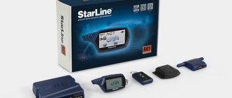
Equipment
Scope of delivery of the Starline A61 alarm system:
- service manual for the use and connection of the security system with diagrams;
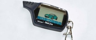
- a control communicator equipped with buttons and a display, which makes it possible to use two-way communication with the car;
- battery for installation in the main key fob;
- a spare communicator that does not have a feedback option and a display;
- microprocessor module for controlling the security system;
- antenna adapter to which a wire with a connector is connected;
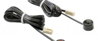
- two-level shock sensor with cable and connector;
- double-sided tape for attaching the antenna module to the windshield;
- case for the main key fob;
- a limit switch designed for installation on the hood or tailgate;
- emergency mode entry button;
- LED to determine system status;
- power cable with 16-pin block;
- a set of wires to block the engine during illegal starting, as well as connection to the standard central locking system.
To ensure complete protection, the owner of the Starline A61 alarm system needs to additionally purchase a siren and limit switches for doors.
The Access Auto channel talked about the configuration of the anti-theft system.
Engine lock
The Starline A61 Dialog alarm system is not equipped with an autostart module. But it has a power relay, the contacts of which are connected to one of the power circuits. This is how blocking is implemented.
Most often, by the way, the fuel pump is blocked. An electric fuel pump is an attribute of all engines with an injector.
By default, the processor is configured to use two contacts - common and normally closed (NC). These two contacts are included in the open circuit. There are reviews that say that using another option would be undesirable. It is better to leave the normally open contact free.
How to install correctly?
During installation, it is necessary to take into account the design features of the vehicle provided by the automaker. Before starting installation, you must turn off the ignition and all electrical equipment, and also disconnect the battery. This will prevent possible short circuits in the system and failure of devices.
Recommendations for placement and installation
The arrangement of elements should be like this:
- The microprocessor module is installed hidden in the car interior; it is advisable to place it under the instrument cluster. The unit is placed with the connector with the wires facing down to prevent water droplets from dripping into the device. Self-tapping screws or plastic ties are used to secure the module. The block must be secured as much as possible to prevent it from moving when exposed to vibrations while driving.
- The antenna adapter is installed on the windshield, in the upper or lower corner. There must be at least 50 mm between the transceiver and metal parts. The working surface of the glass is first cleaned.
- The siren is installed in a hidden place in the engine compartment. There should be no sources of elevated temperatures near the device. The horn is directed downward to prevent moisture from accumulating inside. The wires must be laid so that they do not touch moving parts of the body.
- The sensitivity and impact controller is installed inside the car. During installation, it is necessary to ensure free access to the device controls. It is advisable to place the controller in the central part of the body.
- The alarm status LED light is installed in a visible place on the console. The wire from the LED to the control unit is laid under the plastic lining of the interior. You need to make sure that the diode cable is not pinched.
- The installation of the emergency key is carried out covertly. During installation, it must be taken into account that the consumer must have free access to the button when he is in the driver's seat.
- Limit switches are installed on the hood, trunk and doors. For installation, special technological holes provided in the body are used. If there are none, you will have to use a drill. The cables from the limit switches are laid under the door trim.
Connection diagrams with symbols
Diagrams will help you connect the device correctly. If the wire length is not enough, then soldering must be used to extend it. The twisting method cannot be used, since it is the most unreliable. The joints will need to be insulated using special tape or heat shrink tubing.
General scheme
Features of connecting the microprocessor module:
- the antenna adapter is connected using a five-pin block and the wire included in the delivery kit;
- The LED is connected via a two-pin plug;
- To connect the service key, a two-pin block is used.
General connection diagram
Main 16-pin connector
The order of connecting the block:
- The red contact is the positive power supply. It must be connected directly to the battery, the electrical circuit must be protected with a fuse. Its value is indicated in the service manual.
- The black contact represents negative or ground. To ensure the alarm is grounded, it is connected to the vehicle body.
- The yellow contact is connected to terminal 15/1 on the switch. When the ignition is activated, a 12-volt voltage should appear on it.
- Outputs of yellow-green and black-green colors are intended for connection to lighting devices of side headlights or turning lights.
- The gray contact is used as a positive siren control input.
- The red/blue wire is designed to connect to door lock limit switches. When they open, a short circuit to +12 V should occur here.
- The black and blue contact is intended for connection to push-button switches. But when the door locks are opened, there should be a short circuit to ground.
- The gray-orange contact is used to connect to the “limit switch” mounted on the hood. When it opens, there should be a short circuit to the body.
- The white-orange contact is intended for connection to the tailgate limit switch. When it opens, there should be a short to ground.
- The black and yellow output is used as a negative contact for the first additional channel. The duration of the signal is regulated by the user; it can range from one to sixty seconds. The channel can be used to control the tailgate opening solenoid or additional devices. When making the connection, you must use another relay.
- The red-yellow contact is used as the negative output of the second additional channel. The signal length is user configurable. You can configure the output for two-step opening of door locks or control of additional devices. The connection is made using a relay.
- The white-yellow contact is the negative output of the third channel. The duration of the signals is regulated by the user, making settings depending on the period of operation of the turbo timer. It is permissible to use a channel to support 12-volt voltage at output 15/1 of the ignition switch. The electrical circuit must be protected by the relay.
- The blue contact is used as the negative output of the fourth additional channel. You can configure it to activate the interior lighting or control the power windows. The electrical circuit must be protected with an additional relay.
- The red-black contact element is used as the negative output of the power unit blocking. The car owner must program the normally open and closed relay contacts.
- The orange-violet contact is used as a negative output for monitoring the state of the handbrake lever or pedal.
16-pin alarm connector diagram
Sensor connectors
Features of connecting controllers:
- The sensitivity sensor must be connected to the microprocessor module using a four-pin block and the corresponding wire. The ground potential is supplied to the controller synchronously with the formation of a pulse on the red-black cable of the security system. To change the sensitivity parameter, special holes are used on the device body.
- The two-level additional controller connects to a four-pin block. For connection, use the wires that are included in the package. The ground potential arrives at the controller simultaneously with the appearance of a pulse on the red-black Starline cable.
Sensor connection diagram
Connecting alarm circuits
Features of connecting electrical circuits of the security complex:
- To connect the built-in engine blocking, you need to break one of the start lines of the power unit. At the break point, connect 2 of the 3 switching contact elements of the built-in blocking relay. For this, thick white-blue and blue cables are used.
- To connect the external blocking of the power unit, break one of the standard engine power lines. An additional relay must be connected to the break point.
- The fourth channel is used to connect the low beam system. The contacts of the blue wire must be connected to the relay and 12-volt power.
Central locking system
The Starline A61 system is equipped with a built-in relay designed to control the standard central locking. Its contact elements are connected to a six-pin block.
Wiring diagram for connecting the alarm to the central locking
Using connector "X7"
The main signaling unit of Starline A61 Dialog is equipped with an additional 4-pin connector. As stated in the instructions, external sensors are connected to it:
To connect a single-level sensor, it is better to use terminal 4 (white wire). There is another option - the sensor is connected to any of the inputs. But then you need to configure it by assigning option 12 a new value.
Let's look at an example. The installation of the Starline D10 sensor was carried out according to all the rules, but, as it turned out during operation, it did not activate the alarm level. The sensor itself is single-level, and the instructions for it say the following:
There are two solutions to the problem:
- Even before connecting, the white and blue wires are swapped;
- No modifications are made, but programming is performed: option 12 is assigned a value of 2, 3 or 4.
When installing, you can use any of two solutions.
Perhaps the reader is interested in what the Starline D10 module looks like in reality:
The device shown in the picture is a tilt sensor. There are no regulators on its body, which entails certain difficulties. But the Starline E61 alarm, as stated on the Starline website, is equipped with a built-in tilt sensor, which, in addition, can be adjusted. The adjustment is carried out during operation, monitoring the system via a smartphone.
Operating instructions StarLine A61 Dialog
Before using the Starline A61 alarm system, the user must install a working battery in the communicator. You need to open the back cover of the device. Insert the power supply into the free compartment, taking into account the polarity.
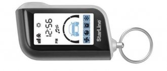
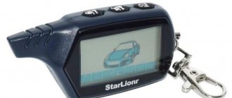
Key fobs
The remote control must be linked to the car alarm in this way:
- When the security mode is turned off and the ignition is off, the emergency button “clicks” once. The key is then turned in the lock to turn on the engine.
- Seven siren beeps will indicate successful entry into the communicator binding and programming menu.
- Then press buttons 2 and 3 on the communicator. These keys must be held until one siren signal is played. If the binding is successful, the communicator will emit a melody.
- The previous paragraph is repeated for each device. The consumer can link up to 4 communicators to the microprocessor module.
- After programming, you must leave the connection mode. A successful exit from the menu will be indicated by five headlight signals.
Meaning of indicators and buttons
Description of the keys:
- First. Used to activate security with or without sound. Activation of protection is carried out by a single press or sequentially. This button is also used to turn on or off the shock sensor by levels; to do this, you need to press it twice. When the ignition is activated, the key allows you to lock the doors.
- The second is designed to disable the security function with or without sound. Pressing, accordingly, must be single or sequential. If you “click” the button twice, this will lead to activation or disabling of the action levels of additional sensors. Briefly pressing the second button with the engine running will unlock the doors. Double click is used to deactivate the Anti-Robbery function.
- Third. Serves to monitor the status of the anti-theft system. If you press the button once, the key fob display will display information about the temperature level in the cabin. By double-clicking, the consumer enables the option to search for a car in the parking lot. This key is used to turn on the engine lock, turbo timer, security, and the “Anti-robbery” function. With its help, you can configure the settings for the timer, alarm clock and current time.
- Simultaneously pressing buttons 1 and 2 will enable the “Anti-robbery” and “Panic” functions, but the “clicks” must be long. The first option is activated when the ignition is on, and the second - when it is off.
- A short simultaneous “click” on buttons 1 and 3 will activate the communicator key lock. To disable this option, use elements numbered 2 and 3.
- If you press first the first and then the third button, the protection mode is activated when the engine is running.
- By successively pressing keys 3 and 1, the option to configure additional channel 1 will turn on.
Labels of buttons on the main and additional remote controls
Description of indicators on the key fob:
- 1 — “Anti-robbery” option icon;
- 2 — two-stage disabling of motor blocking;
- 3 — silent car protection is enabled or disabled;
- 4 — emergency service mode;
- 5 — “Turbo timer” option;
- 6 — indicator of automatic activation of car protection;
- 7 — power unit blocking is activated or disabled;
- 8 — key fob key lock is enabled;
- 9 — charge indicator of the power supply in the remote control;
- 10 — car protection zone indicator;
- 11 — the additional pressure change controller was activated;
- 12 — icon of a running car engine;
- 13 — the “Anti-robbery” option is activated;
- 14 — the Starline module for determining the vehicle’s coordinates is turned on, connected additionally;
- 15 — the luggage compartment of the car is open;
- 16 — vehicle ignition is activated;
- 17 - current time;
- 18 — countdown timer activated;
- 19 — the “Alarm clock” option is enabled;
- 20 - indication of the transmission of commands to control the alarm (if the icon is not lit, this indicates a lack of feedback);
- 21 - door locks are locked or open;
- 22 — vehicle security mode is activated without sound and alarm signals;
- 23 — the handbrake lever is not raised or the pedal is depressed;
- 24 — the optionally installed tilt controller has been activated;
- 25 — user authorization by password is enabled (the PIN code can be one-, two-, or three-digit).
Indication of symbols on the remote control screen
Setting up remote control functions
To change parameters, perform the following steps:
- Button 3 is used to set the time, pressed and held. You must hold down the key until the communicator emits signals and the siren goes off. To set the minutes, you need to press the third button again. Use keys 1 and 2 to decrease or increase values.
- After pressing the third button again, you go to the alarm clock settings menu. Keys 1 and 2 increase and decrease clock parameters. After the next “click” the minutes are adjusted. Using key 3, you enter the menu for activating or disabling this function. To change parameters, use buttons 1 and 2.
- The timer value is adjusted by briefly “clicking” on the third key. Pressing the first and second buttons changes the minutes parameters, increasing and decreasing respectively. To activate or deactivate an option, press the third key.
Programming security and service functions
Features of setting up the main system options:
- The alarm mode is switched off briefly when the siren is on, and the second button is pressed. The alarm will sound three times, and the side lights of the car will also blink. The controller zones that triggered the alarm will be displayed on the communicator display.
- The engine is blocked automatically. To disable this option, you can use the second key fob button or the “enter emergency mode” service key. When performing the task, the ignition must be turned off.
- The third key of the communicator is responsible for setting the immobilizer. It is pressed and held until the key fob emits two beeps: one long, the second short. When the cursor mode is turned on on the communicator display, you need to move the indicator to the position of the “Immo” icon using the third button. After selection, the first key is pressed. The vehicle's side lights will blink once and the engine lock indicator will appear on the screen.
- The second key helps to disable the “Anti-robbery” option. After pressing, the siren will be deactivated and the LED indicator will begin to blink. To turn off the security mode, press button 2 again.
- To activate the “Turbo timer” option, you need to lift the parking brake lever. When the diode indicator starts to light without interruption, within thirty seconds you need to remove the key from the lock and leave the car. All doors are locked, the first key is pressed on the communicator.
- To temporarily disable the sensitivity controller, button 1 of the key fob is “clicked” twice. The first sensor will turn off with warning signals. To deactivate both levels of the controller, press the same remote button again. The device is reactivated using key 1.
- To temporarily disable the first level of all additional controllers, you must double-click the second button on the communicator. The sensors are deactivated by briefly double-clicking on key 2. The controllers are re-enabled by pressing the second button.
User Vladimir Gorokhov showed how the option to open the luggage compartment works on a car in which the Starline A61 system is installed.
Setting up autorun
The Starline A61 Dialog signaling model does not provide an automatic engine start function, however, the consumer has the opportunity to install an additional control module. To do this, you need to connect an external unit from the manufacturer Starline to the alarm system. The option will be controlled using your phone.
List of commands:
- 20 - stopping the car engine;
- 21 — remote engine start;
- 26 - starting the power unit and interrupting further connection with the security system.
Option "Turbo timer"
Let us immediately note that the Starline A61 alarm system can only be a semi-automatic timer. That is, during operation, the handbrake is first activated, and then the key is turned to the OFF (ACC) mark. If the sequence is broken, the timer does not work - the ignition is turned off when the key is turned immediately.
The duration of the turbo timer is configured programmatically. The default minimum is one minute.
We will assume that the owner is satisfied with the considered mode of operation. All that remains is to make all connections correctly. During installation the following errors are usually made:
- To support the ignition they are trying to use the built-in relay.
- The control wire is connected to the micro button of the brake pedal. In principle, this option is acceptable, but it is better to use handbrake control. By the way, the instructions provide both options (see diagram).
- The Starline A61 Dialog alarm system can be considered an entry-level system. But there is no need to connect the control cord directly to ground - the processor will understand that they are trying to deceive it, and the timer will not be activated.
The correct option is shown on the left:
And the support relay should be connected like this:
There may be several relays themselves, but the total current flowing through the windings should not exceed 200 mA. Finally, for the timer to start running, option 16 is assigned a new value of 4.
Advantages and disadvantages of alarms
Advantages of the Starline A61 Dialog system:
- resistance of the control unit to electronic hacking (it is almost impossible to intercept a signal using a code grabber or scanner);
- quiet operation of the microprocessor module (thanks to this, an attacker will not be able to detect the control unit by noise);
- long range (this parameter is affected by local developments, but the operating range still remains high);
- efficient operation in urban environments;
- the case is made of high-strength material, so the likelihood of damage due to a fall is minimal;
- the presence of backlight greatly simplifies the use and setup of the alarm system in the dark;
- An intuitive menu in the remote control allows you to quickly and easily configure basic alarm parameters;
- the ability to monitor vehicle coordinates from a mobile device running Android or iOS operating systems;
- compliance with weather conditions typical for Russia and neighboring countries.
The list of shortcomings is compiled in accordance with consumer reviews:
- there is no auto-start function, although all modern alarm systems from other manufacturers have it;
- rapid discharge of the power supply in the communicator, which is why car enthusiasts will have to periodically change the batteries.
Batteries are quickly discharged when setting up the security system.
Improvement of built-in relays
Central locking is a standard feature on modern cars. There is a central locking control unit, but the alarm system does not need to be connected to it. But then, to control the locks remotely, you will have to use the car’s standard key fob. To combine the central locking system with the signaling, one or two low-current wires are connected to it. But this connection option is not always implemented, that is, not on all cars.
The problem is solved by installing an additional actuator.
An additional actuator is mounted in the driver's door. Its operation emulates pressing the “dog”. As you can see, everything looks reliable and simple.
Many people decide to make a radical modification: you can connect not one, but all standard actuators to the connector shown in the diagram. The role of the control module then passes to the car alarm. The Starline A61 Dialog model does not meet these goals well - there is no control input that monitors the position of the “dog”. In general, control is carried out only from the key fob. And the main block itself is modified as follows:
The tracks leading to the power contacts of the relay were cleaned and soldered.
The diagram shown above is copied from the installation instructions. After modification, the fuse rating can be increased to 20 A.
Photo gallery
Photo of the Starline A61 security complex:
A61 system components
Control module
Transceiver block
Connection diagram A61
For an experienced car enthusiast, the A61 car alarm connection diagram is quite simple. It allows you to install the system and connect additional modules yourself.
Video
User Alexey Avtoelektrik showed the operation of the security system installed on a Mazda 6 car.
Do you have any questions? Specialists and readers of the AUTODVIG website will help you ask a question
Was this article helpful?
Thank you for your opinion!
The article was useful. Please share the information with your friends.
Yes (100.00%)
No
X
Please write what is wrong and leave recommendations on the article
Cancel reply
Rate this article: ( 2 votes, average: 5.00 out of 5)
Discuss the article:
What happens if you don’t set the time on the Starline remote control?
An incorrectly set key fob clock entails a number of additional inconveniences. Automatic engine start may occur at unexpected times, the alarm may not work correctly, and the engine start timer may not start at the appointed hour. After all, the alarm is based on the indicators set in the Starline key fob. You need to configure all parameters correctly.
PROMOTION: SALE OF NEW CAR 2022 PRODUCTION
Below is how to set the time on the Starline key fob of various series. Even correctly set parameters can go wrong, and this can be caused by several factors. The first is the usual mechanical damage to the Starline key fob. Due to impact or heavy loads, the remote control may break, its screen may crack, and settings may be lost.
The second - and most common - is a weak or discharged key fob battery. If the charge is weak, the clock setting can easily go wrong. A special charge indicator, which is equipped with almost all Starline alarm key fobs, will help you track the moment of timely replacement.
After replacing the battery with a new one, you need to remember that all system parameters are reset. Therefore, you will need to re-set the time on the key fob. Also, changing parameters may be affected by a system or software failure of the remote control itself. In this case, it will need to be replaced or the help of a qualified service center specialist. But you can change the battery and set the clock again yourself.
What are the consequences of incorrectly setting the clock on the remote control?
Obviously, if the time on the Starline alarm remote control is incorrect, the system will remain operational and will still protect the car from burglary or theft. However, the user will be deprived of a number of advantages.
In critical cases, when it is late, you will have to start driving on “cold and viscous” oil, which does not provide proper lubricating properties. If repeated for a long time, this can even lead to engine damage. So, correctly setting the time on the Starline key fob not only allows you to take advantage of all the benefits of the system, but also take care of the proper operation and safety of the engine.