01/26/2022 99,764 Volkswagen Transporter
Author: Ivan Baranov
Readers of our site know that the fuse box plays one of the main functions in the operation of the vehicle. After all, a lot depends on the performance of the block elements. Therefore, in this article we will tell you what the fuse diagram of the Volkswagen Transporter T5 looks like, what the components of the block are responsible for and how to replace them.
[Hide]
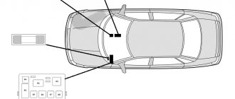
Block in the cabin
Almost all inserts and fuses are mounted inside the car. There is a breakdown into 4 parts to reduce the size of the block and simplify its design.
Main unit
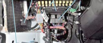
The installer is mounted in the driver's feet; to access it, a special panel must be opened. The fuses and relays themselves will appear behind it. When servicing the vehicle, you may have to remove the module. Some inserts are installed on the back of the device.
Additional fuse block
Auxiliary compartments are installed above and below the main module. This makes repair work much easier and faster. Here, mainly elements responsible for auxiliary electrical equipment are installed.
Additional relay block 1, 2
Mounted in remote locations. The relays are installed in the dashboard, strictly in the center. To access the device, open the installer's cover.
The second auxiliary module is located under the driver's seat. Here are the main protective elements of power circuits and energy-intensive equipment.
Emergency procedures for VW T5 Transporter. Replacing fuses VW T5 Transporter
7. Replacing fuses
Circuit breakers
Due to the fact that the car is constantly being improved and the purpose of fuses is constantly changing, it is impossible to provide a reliable specification of fuses in this section. The location of the fuses can be obtained from a Volkswagen Commercial Vehicles Dealership.
One fuse can protect the circuits of several electrical consumers. And vice versa: one consumer can have several fuses. Replace fuses only after eliminating the cause of their blown.
If the new fuse quickly blows again, have the relevant electrical equipment checked by a workshop.
WARNING The vehicle's electrical system contains high voltage and can cause electric shock, severe burns or death! Do not touch the ignition system wires under any circumstances.
Avoid short circuits in electrical equipment.
WARNING Using improper fuses, repaired blown fuses, or shorting unfused electrical circuits can cause fire and serious injury. Never install fuses with a higher current rating than required.
Replace blown fuses only with fuses of the same rating (color and markings must be identical) and size. Repaired fuses (so-called
"bugs") do not use!
It is prohibited to replace fuses with pieces of wire, paper clips and other improvised means!
Note To avoid damage to the electrical system in the car, before replacing the fuse, be sure to turn off the ignition, lighting (headlights, interior lighting, etc.) and all electrical devices and remove the key from the ignition switch.
Using high amperage fuses may cause damage elsewhere in the arterial circuit.
Protect exposed fuse boxes from dirt and moisture.
Dirt and moisture in the fuse box can cause damage to electrical equipment.
One electrical appliance may have several fuses. One fuse can protect the circuits of several electrical consumers.
Front panel fuses
Opening the fuse panel in the front panel (Multivan)
– Open the bottle holder in the front panel. – Squeeze both levers on the back of the bottle holder and remove the bottle holder.
– Insert a flat object, such as a screwdriver from an on-board tool, onto the top edge of the transparent cover and carefully lift the cover.
Opening the fuse panel in the front panel (Transporter)
– Press the recess under the drink holder and remove the lid towards the rear. Note The fuse box cover must be removed and installed correctly, being careful not to damage the vehicle.
Protect exposed fuse boxes from dirt and moisture. Dirt and moisture in the fuse box can cause damage to electrical equipment. There are other fuses in the vehicle that are not mentioned in this section. They can only be replaced at a service station.
Fuses in the engine compartment
Opening the fuse box in the engine compartment
– Open the hood. – If necessary, remove the battery cover located on the rack. To do this, turn the quick release locks 90°. – Remove the partition (1) by moving it upwards. – Turn both quick release locks by 90°.
– Grasp the fuse box cover from the front and fold it up.
Closing the fuse panel in the engine compartment
– Close the fuse box cover and turn both quick release locks. – Insert the partition. At the same time, make sure that both recesses of the partition simultaneously cover the fuse cover jumper and the vertical partition jumper.
Replacing blown fuses
Note The fuse box cover must be removed and installed correctly, being careful not to damage the vehicle.
Protect exposed fuse boxes from dirt and moisture. Dirt and moisture in the fuse box can cause damage to electrical equipment. There are other fuses in the vehicle that are not mentioned in this section. They can only be replaced at a service station.
Replacing blown fuses
Preparation
– Turn off the ignition, lights and all electrical consumers. – Open the relevant fuse box.
Recognizing blown fuses
A blown fuse can be identified by a burnt-out metal wire. Shine a flashlight on the fuse. This will make the burned area noticeably better.
Replacing fuses
– If necessary, use the plastic tweezers stored in the fuse box cover. – Grab the small fuse from above. Grab the large fuse by sliding the tweezers to the side. – Remove the blown fuse – Replace the blown fuse with a new one of the same amperage (color and markings must be identical) and of the same size. – Replace the cover.
Note Using high amperage fuses may cause damage to the electrical circuit elsewhere.
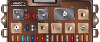
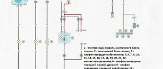
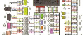
Fuse and relay diagram
The fuse panel wiring diagram is not made in a single design. A system that is too complex is difficult to read and difficult for readers to understand. For the convenience of users, the decoding and description of all FV T4 fuses produced in 1992, 1995 and 1997 are given separately.
EMM T4 block
An additional area of body electronics is installed in the car's interior. The device is responsible for controlling basic mechanisms and electrical appliances. All electrical control, switches and indicator lights come from here.
ABS unit
The traction control system is protected through fuse element F14. The power line of the device runs here. The indicator part on the device is mounted through fuse F16. Split protection ensures complete system security.
Window lifters
A power window fuse – F14 – is also installed nearby. There are no drive relays in the circuit. The relays are mounted directly next to the drive.
central locking
The above element No. 14 is also responsible for the operation of the system. There are no relays in the circuit.
Glow plug fuses and relays
Diesel cars are equipped with monitoring systems. The T4 design has a separate heating element control module. The device circuit relay is located in a special compartment, along with the rest of the relays.
The spark plugs for cylinders 1, 2, 3 and 4 are protected by power fuse F1, installed under the hood.
Air conditioner relays and fuses
Elements F14, installed in the lower left part of the instrument panel, are responsible for the operation of the clutch. The outside air intake system is activated via relay R6.
This division is typical for most modifications. In some cases, there are additional protections in the car interior and a special thermistor at the fresh air inlet from overboard.
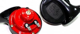
Signal
The sound signal system in the car is quite simple. There is a standard fuse F13 and power relay No. 11.
Cigarette lighter fuse
Insert F22 of the main unit under the dashboard is responsible for the element and an additional socket in the rear of the car (if equipped).
Cooling Fan
The cooling system of the power plant consists of two fans. Fuse F19 from the main unit is responsible for powering the electronic unit of the cooler control system.
The forced fluid circulation pump is turned on by relay insert R1 from the main module installed in the cabin. The fans themselves are protected by inserts F2 and 3. Repairing the main fan switching circuit is complicated - you will need to check several individual elements.
Generator fuse and relay
Using the 2001 modification as an example, the machine's generator set control system is examined separately. The power circuits of the device pass through relays No. 7 and 8 of the main unit. There is also a voltage regulator fuse F5.
This arrangement of elements is relevant for versions:
- T424;
- T48;
- T46;
- T419.
In other configurations, the installation locations of parts may differ.
Heater
On most cars, the heater fan control circuit is protected by fuse F6. The cooler operation circuits at low speeds are protected through relay No. 4. For maximum rotation speed there is a separate switch R1. In some configurations this may be relay R2 of the interior unit.
Rear heater
The car comes with a separate heater installed from the factory. Depending on the configuration, fuse F14 or 15 may be responsible for turning on the fan. The devices are controlled by fuse link F4.
The relays are located at positions R3/4 for low and high fan speed respectively.
Main relay T4
It is a separate unit where the main parts of the engine compartment electronics are concentrated. The device controls all important processes in the machine and is not serviced. The manufacturer made the module non-repairable.
Relay 109: what it is responsible for
Ensures that the electronic engine management system is turned on. It supplies power to sensors installed in the cylinder head and cylinder block. To find the relay assembly, you do not need an article number. A regular insert sold in every store will do here.
Number of turn relay T4
The standard fuse is installed under number F16. Relays and lamp breakers are placed separately under the instrument panel. You can recognize the exact location of the parts by a characteristic clicking sound.
38 VW T4 relays
These are breakers for the additional pump that supplies antifreeze to the rear heater and are installed next to the other switches inside the unit.
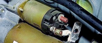
Starter relay
The engine starting system is equipped with a standard pull-in relay. The device is located on the body of the electric motor. The engine blocking relay after starting the internal combustion engine is located under number F36.
If a part burns out, you can use an analogue from Valeo.
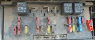
Block under the hood
This unit is located on the cover in front of the battery.
Scheme
Decoding
| 1 | 60A Glow Plug Relay |
| 2 | 50A Cooling fan motor |
| 3 | 50A Cooling fan motor |
| 4 | 50A Anti-lock Braking System (ABS) |
| 5 | 110A/150A/175A generator |
| 6 | 30A Stability control system |
| 7 | 30A Anti-lock Braking System (with ESP) |
| 8 | 5A Stability control system |
Wiper relay: where is it located?
The system switches are divided into two independent sections. The rear instrument is activated via R2. The front wipers are powered by an R8 switch.
Relay 174 T4: what is it responsible for
On cars of 2002 and other modifications, it is responsible for turning on the rear wiper of the car.
Low beam
Similar to most of the manufacturer's cars, the head optics relays are located near the headlights. The corresponding fuses F1 and F2 are mounted in the main cabin unit.
Gasoline pump
Regardless of the type of fuel consumed, the control circuits for the fuel pump in the tank pass through fuse F18. The power relay is installed at number 12 of the above module.
Charging relay
The monitoring device is located in the engine compartment near the battery itself. The part looks like a plastic block attached to the wing of a car.
Trip relay SOR-CT4-T6 240Vac– 250Vdc
The device is mounted in the engine compartment or inside the car - the exact position depends on the year of manufacture and equipment of the car. The device cannot be repaired, although some users are trying to resolder the internal parts.
Climate control
On T4, power fuse F06 is responsible for the system. The device control circuits are powered through fuses 13/14 of the auxiliary module. Relays R5/7 are responsible for activating the main devices and power circuits of the device. Depending on the year of manufacture and modification of the car, the location of the main elements may differ slightly.
Relay T45 for refrigerator
Safety insert F19 is responsible for activation. And the switch is installed in close proximity to the device.
Removal and replacement process
Required tools: flat screwdriver, keys 10, 14.
Engine compartment
The procedure is as follows:
- Remove the negative terminal after turning off the ignition.
- While pressing the latches, remove the top cover from the unit.
- Remove the broken fuse or relay. If the power multi-function fuse at the end has blown, unscrew the nuts with a 14mm wrench, remove the wires from the studs and, pressing the plastic clips, pull out the part. Completely replaced.
- Install a new element, having first eliminated the source of the short circuit.
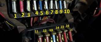
Additional relay block 2
The mounting block is located behind the dashboard in the center. Access to it is limited.
Description
| 1 | (106) Auxiliary heater relay |
| 2 | Audio/telephone speaker switching relay |
| 3 | (53) Heater Fan Motor Relay - Rear (Warm Air) |
| 4 | (114) Heater Fan Motor Relay - Automatic Temperature Control |
| 5 | (152) Heater coolant valve relay (rear heater) |
| 6 | (38) Air intake switch drive relay (air conditioning/heater) |
| 7 | (53) Alternator relay (AES, with 150A alternator) |
| 8 | (53) Alternator relay (ACV/AUF, with 150A alternator/automatic transmission/automatic temperature control) |
| 9 | (175) Start inhibit switch relay/reversing light relay |
| 10 | (87) Wheel hub connection control unit |
Article on the topic: How to change rear silent blocks on a Kia Rio
***** In some trim levels, another unit may be located under the driver’s seat. The following items may be located there: (214/426) Auxiliary battery relay, (403) Auxiliary heater relay, (30A) Auxiliary hydronic heating system, (5A) Sockets , etc.