The camshaft sensor in the VAZ-2114, however, as in other modern cars, has a fairly important role. Correct fuel injection, and therefore its consumption, depends on its correct operation. This part was first installed on the VAZ “fourteenth” in 2007. Accordingly, before this, the design of the car did not provide for the presence of a camshaft sensor. Considering the fact that the manufacturer nevertheless decided to supplement the design of the car with it, we can conclude that the use of this device provides some advantages.
Signs indicating a faulty camshaft sensor
Now let's talk about how we can accurately recognize the failure of the DF. These are, in particular:
- the “Check” sign lights up on the instrument panel;
- problems and failures that appear in self-diagnosis mode;
- deterioration in dynamics and reduction in power;
- increase in fuel consumption.
It should immediately be noted that these signs may also indicate some other problems. However, one of them is a malfunction of the camshaft sensor. If, after starting the engine, you see the Check sign on the dashboard, while the starter continues to crank for a few more seconds, then the problem is most likely in the DF. The thing is that if it fails, then when the engine starts, the ECU will wait for some time to receive information from the camshaft sensor.
If the electronic control unit does not receive any signal from the DF, it will still give the command to start, based on the ignition system. The on-board computer will also indicate a problem with the camshaft sensor. In this case, error codes will light up on its display - 0343 or 0340. These numbers indicate either an open circuit in the sensor circuit or a failure of the device itself. Accordingly, the diagnostic process is greatly facilitated.
In most cases, damage can be detected by visual inspection. In the VAZ-2114, the camshaft sensor is located in close proximity to the cylinder head, near the air filter. Carefully inspect the DF body - there may be some mechanical damage on it. Their presence is almost a 100% sign of a malfunction. Next, you should check the contacts for possible moisture. They can short-circuit from this; accordingly, the sensor simply cannot transmit information to the electronic control unit.
In addition, check the contacts for oxidation and rust, due to which information is not transmitted to the ECU correctly. The next step is to inspect the chain. If you find broken or damaged wires, replace them and then check the operation of the car. If no problems are found, you should continue your search.
Repair
Before checking the DPRV or before starting any independent actions, you need to familiarize yourself with the connection diagram for the VAZ 2110 camshaft sensor, as well as the features of its installation in the engine body.
The type of action performed depends on what signs of malfunction have been identified:
- if there is visible mechanical damage to the wiring or exposure of live parts, it must be replaced, but repairs in the form of re-insulation of the wires are also possible;
- If the sensor is mechanically damaged, it must be replaced. It is not recommended to repair or disassemble it;
- if the connector is dirty, it is necessary to reconnect with a visual inspection and cleaning of the electrical contacts;
- Wear of the connection connector requires its maintenance or replacement of the sensor. Maintenance consists of ensuring a tight fit of the connected parts;
- When checking the electrical wiring or sensor with a voltmeter and identifying deviations, it is necessary to replace the faulty element. When connecting the voltmeter probes to the electrical power contacts, the sensor resistance should not be lower than 550 Ohms or higher than 750 Ohms;
- If an internal malfunction of the sensor is detected during computer diagnostics, it must be replaced.
Replacing the DPRV is carried out by disconnecting it, dismantling the faulty one, installing a new one and reconnecting the power connector.
It is important to note that after performing any actions aimed at eliminating identified faults, it is necessary to recheck the engine operation.
The operating manual does not recommend disabling the sensor yourself and further operating the vehicle.
What is he like?
The phase sensor operates on the principle of an elementary Hall sensor. Installed only in the camshaft area on both 8 and 16 valve engines. The device reads data from the engine camshaft using a gear mounted on the shaft with two missing teeth. These two teeth are positioned so that every time the device is hit, the first piston of the engine is at top or bottom dead center. Information signals about the location of the camshaft are sent to the engine control unit, which, in turn, monitors and changes the ignition angle. It began to be used at VAZ factories on the first cars with distributed fuel injection.
It is worth noting that carburetor engines do not have this unit, because their mechanism has a vacuum-mechanical ignition timing system.
The main function of the camshaft position DF or phase sensor is to constantly adjust the ignition angle while the engine is running. Thanks to its use, VAZ family engines began to transmit power more efficiently with reduced fuel consumption. The main indispensable use of the phase sensor remains for two camshaft, 16-valve engines, which without it cannot operate evenly and economically according to the folded factory design.
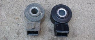
VAZ-2112 sensors 16 valves and their location: diagram, photo, video
Replacing the temperature sensor on a VAZ 2110 in 5 minutes!
The efficient operation of the injection engine is ensured by a set of sensors. They all connect to the ECU. Lada hatchbacks of the 2112 family were produced only with injection engines, and two varieties of these internal combustion engines are 16-valve. We will talk about them further. All VAZ-2112 sensors, their location and appearance will be shown in the photo. The excess oil pressure sensor, which is not connected to the ECU, is shown in the video.
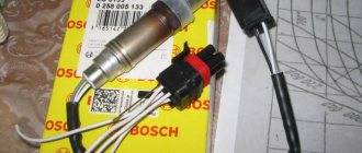
Understanding the oxygen sensor
It is necessary to determine the sensor articles not by the engine model or even by Euro standards, but only by the ECU unit.
The number of oxygen sensors can be two or one - it all depends on environmental standards. AvtoVAZ also used two types of sensors - 0 258 005 133, 0 258 006 537 (BOSCH part numbers). The first of them are compatible with BOSCH M1.5.4, MP7.0 and January 5.1 controllers. Newer sensors were connected to the BOSCH M7.9.7 ECU (January 7.2). The two different types of sensors differ even in appearance.
The ECU unit in “Dozens of VAZs” is located under a plastic cover. It is located near the front passenger's foot.
The red arrow marks the first, that is, the main sensor. The top photo corresponds to engine 21124 (1.6 l).
VAZ-21120 engines (1.5 l) could meet the Euro-3 standard, and then an “extended” catalyst was welded behind the main sensor. The second sensor was located behind it, that is, behind the “can”. Let's clarify:
- The Euro-2 standard corresponds to a design with one sensor (main);
- During the transition to Euro-3 standards, a second sensor was added (blue arrow).
By the way, the 24th engine can meet Euro-4 standards.
Which VAZ engines have a phase sensor
Main set of sensors for 16-valve VAZ-2112 engines
The ECU must control many parameters at once
The most important information will be the position of the crankshaft. You can turn off all sensors except the DPKV, and this will not lead to the engine stopping. Let's list all the elements one by one:
Let's list all the elements one by one:
Let's take a look at how all the elements look in real life. Shown are pictures of VAZ-2112 sensors (16-valve internal combustion engine).
Everything said above is true for two engines at once - for units 21124 and 21120 (1.6 and 1.5 l).
You cannot unscrew the DTOZH sensor without draining the coolant. And to disconnect the sensor means to disconnect the connector, but not to dismantle the sensor itself.
Where is which sensor located - engine compartment diagram
Let's look at another picture.
It is important to understand where the following elements are located:
The location of the phase sensor is indicated in the previous chapter.
How to check Niva Chevrolet phase sensor
Never unscrew the speed sensor. It will be difficult to install it in a way that maintains a seal.
Articles
For oxygen sensors, the designation 21120-3850010 was first used. Then an article appeared with the numbers 1118 (see photo). It appears to be a new type of sensor. It will be easier to use BOSCH articles.
We list the article numbers of the remaining sensors:
- Mass air flow sensor (21124 or 21120): 21083-1130010-01, -10, -20;
- Mass air flow sensor (motor 21120 with ECU January 4.1): 2112-1130010, -01;
- DPDZ: 2112-1148200;
- РХХ: 2112-1148300-02;
- DPKV: 2112-3847010, -01, -03, -04;
- DTOZH: 2112-3851010, -01, -02, -05;
- Speed sensor: 2110-3843010-13, -18;
- DPRV: 2112-3706040, -02, -03;
- DD: 2112-3855020, -01, -02, -03;
- Oil pressure sensor: 2106-3829010, -01, -02;
- Antifreeze level sensor: 2110-3839310-10, -11, -12, -13, -14;
- Coolant temperature indicator sensor: 2101-3808600, -02, 2106-3828010.
The last three sensors are not connected to the ECU. However, a rough road sensor (2123-1413130) can be connected. It affects the operation of the engine, although it is attached to the body.
Engines with ECU January 4.1 do not have oxygen sensors.
In general, on VAZ-2112 hatchbacks, sensors may be different from those indicated in the list. But then we are talking about an 8-valve engine. And everything that we indicated applies to 16 valves, here is a diagram of this engine.
Checking the coolant temperature sensor VAZ 2110
Determination of DF failure
If it breaks down, minor problems arise with idle stability; when starting to move, a trimming effect is possible, as well as increased fuel consumption. These symptoms are associated with the failure to receive on-board computer data on the ignition angle at a certain point in engine operation. If there is no signal from the sensor, the control unit enters emergency mode, that is, it begins to work on a predetermined program without a sensor and issues an emergency error “0340” or “0343”.
Why is it needed and checking the sensor
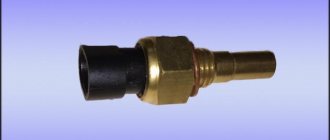
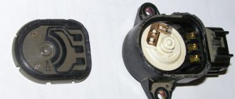
VAZ 2110 camshaft sensor
This electromagnetic sensor is used in the car to carry out most operations, which is sent by the on-board control system. Its readings are very important, since without this data it will be impossible to synchronize the ignition system and injector operation. It is this small device that allows you to distribute the time between supplying the fuel mixture to the engine cylinders. Its location is very simple. It is located on a bracket near the generator drive pulley. Sometimes, problems with this device can be mild. All you need to do is take a few simple steps and you don’t have to worry about replacing the device. Frequent problems with constant use of a car may include:
- When using a car, dirt gets onto the sensor from the timing belt. It forms on the belt as a result of oil leakage from the engine cover. The consequences of such an accumulation of dirt can be problematic starting of the car, poor acceleration, low speed (rarely exceeds 3,500 revolutions).
What needs to be done before replacing the DPKV
When symptoms of a malfunction appear, you need to check several points due to which the control unit is not receiving proper information.
PHASE SENSOR.FULL OPERATION CHECK
HELLO EVERYONE, IN THIS VIDEO I WILL SHOW HOW TO DIAGNOSE A PHASE SENSOR
.THE PROCEDURE IS SIMPLE AND...
Quick check of the phase sensor
How to quickly check the phase sensor
.
- Inspect the DF for external damage.
- Make sure that no moisture gets on the contacts.
- Check contacts for oxidation.
- Make sure that the electrical wiring near the unit is intact.
If nothing was found during a visual inspection, then it is necessary to dismantle the device. How to change the camshaft sensor on a VAZ 2114?
Dismantling any sensor or repairing electrical wiring should always be carried out only with the battery disconnected, otherwise you can complete the repair not only by replacing the burnt circuit, but also by purchasing a new vehicle.
Dismantling on an 8-valve engine is not difficult. Where is the phase sensor located on the VAZ 2114? It is located on the right, on the top of the engine, near the air filter. It is secured with one 10mm wrench bolt. With a few simple movements, the bolt is unscrewed and the sensor is removed. After the unit has been removed, it is necessary to close its structural socket from accidental entry of foreign objects.
Description of the procedure for replacing the timing belt VAZ 2110, (2112) 16 valves
Former flagship of the Russian automobile industry VAZ 2110 with a 1.5 16 valve engine. Scheduled replacement of the timing belt 30,000 km after the last replacement. The autopsy showed that if they had not changed it today, then tomorrow there would have been more work for our mechanic. In general, we recommend that all customers check the condition of the belt at least once every 5,000, or once a year. But knowing the quality of our spare parts, more often is better. On this engine, if the belt breaks, almost all the valves bend. The article is also relevant for VAZ 2112))
We look, remember and don’t let it get to that point.
The patient became five millimeters narrower and generally looked very bad. We send him to the honor board.
And here is the hero of the occasion himself.
We remove the absorber and power steering reservoir so that they do not interfere in the future.
We loosen the bolt by seventeen, the tension roller of the service belt and remove the last one. It will not be possible to remove it completely because the engine mount is in the way. If the belt requires replacement, you will have to unscrew the engine mount.
Remove the tension roller. We unscrew the bolts securing the upper protective cover; they are hexagonal.
Remove the right wheel, plastic mudguard and drain the antifreeze.
We see the crankshaft pulley. Using its bolt, clockwise, rotate the crankshaft until the marks on the camshaft pulleys and the timing belt protective cover match.
Markings on the left exhaust camshaft. The mark on the protective cover is highlighted in red.
Likewise for the intake camshaft. He's on the right. Its pulley has an inner ring for the phase sensor, so it is very difficult to mix up the pulleys.
Remove the crankshaft pulley. Let's lock the crankshaft with the help of a friend. We put him in the car and force him to turn on fifth gear and press the brake all the way. And at this time, with a slight movement of your hand, unscrew the crankshaft pulley bolt. Remove it and the lower protective cover.
We see that the mark on the sprockets and the slot on the ebb of the crankshaft cover coincide.
Loosen the seventeen bolts of the tension and idler pulleys and remove the timing belt. Then the videos themselves. We change them anyway.
We lock and unscrew the camshaft pulleys and remove them. Remember that the right camshaft has a pulley with an inner ring for the phase sensor. The picture should look like this.
We unscrew everything that holds the protective plastic cover and remove the latter. Unscrew the three bolts holding the pump. They are hexagonal.
The pump for a sixteen valve engine is slightly different from the usual for an eight valve engine. It has a small threaded ear for attaching the protective casing.
Lubricate the gasket with a thin layer of sealant and put the pump in place. Tighten the fastening bolts. We put the protective cover in place. We make sure that he sits in his place, otherwise he will rub the belt. If everything is in order, tighten everything that holds it and install the camshaft pulleys and new rollers.
We check that the marks on the camshafts and crankshaft match. We install a new timing belt. If there are no directional arrows, put it so that the inscription is read from left to right.
The right, or descending, branch of the belt should be tight. You can turn the right camshaft clockwise a few degrees, put on the belt and turn it back. In this way we will stretch the descending branch. The tension roller has two holes for a special key. You can find it in any auto store. The issue price is 60 rubles. To tension the timing belt, insert a special key and turn the roller counterclockwise. Since there is a lot of controversy about tensioning the timing belt, we will write this: a tensioned belt should not have a sag between the camshafts of more than 5 mm when pressed and 7 mm on the longest branch (specially experimented). Remember: an overtightened belt reduces the service life of the pump, and an undertightened belt can lead to cylinder head repair. (photo below)
We check all the marks. We turn the crankshaft two turns and check the marks again. If the pistons and valves do not meet and the marks coincide, then accept my congratulations. Then we put everything back in place in the reverse order of removal. Don't forget to tighten the bolts. We tighten the service belt roller with the same wrench as the timing belt tension roller. Fill with antifreeze and start the car. We wish the belt many years of service, but don’t forget to check it periodically; after all, it was made in Russia.
DF cost
The cost of a phase sensor today fluctuates around 300 rubles, the price is insignificant, so there will be no special costs when installing a new unit.
Here's how to change the VAZ 2114 phase sensor without much expense in a short period of time. Now certain engine operating cycles will be strict and uninterrupted. Have a good trip and pleasant fellow travelers!
The VAZ 2114 model car has many sensors installed that are responsible for certain functions. One of the main controllers is the camshaft position sensor. The device has been installed on domestic cars since 2007. In this article we will look at the phase sensor, its features, as well as issues related to replacement on 8-valve and 16-valve engines.
Throttle position sensor (TPS) model 2112-1148200
Design of the throttle position sensor VAZ 2114, 2113, 2115 model 2112-1148200
The throttle position sensor (TPS) of VAZ 2114, 2113, 2115 model 2112-1148200 is mounted on the side of the throttle pipe opposite the air shutter control lever. TPS is a potentiometric type resistor, one of the contacts of which receives a reference voltage of 5 V from the ECU, and the second one receives a negative voltage from the controller. From the terminal connected to the moving contact of the potentiometer, the output pulse of the TPS is sent to the controller. When the accelerator pedal moves, the throttle valve shaft transmits its rotational motion to the throttle valve sensor, causing a change in the voltage of the TPS output signal. When the throttle valve is closed, the output pulse of the TPS VAZ 2114, 2113, 2115 must be within 0.3...0.7 V. When the air valve is opened, the output signal increases, and when the throttle valve is opened by 76...81% according to the diagnostic device, the output voltage must be 4.05...4.75 V. By measuring the output voltage of the TPS pulse, the ECU determines the current position of the air gate.
Information about the location of the throttle valve is needed by the controller to calculate the ignition timing, the duration of injection pulses and the IAC state. By monitoring changes in voltage, the ECU determines whether the throttle valve is opening or closing. The ECU perceives the rapidly increasing voltage of the TPS pulse as evidence of a growing need for gasoline and the need to increase the duration of injection pulses. The throttle sensor is not adjustable. The controller uses the lowest TPS signal voltage at idle as a reference point (0% throttle opening). Breakage or weakening of the VAZ 2114, 2113, 2115 TPS fasteners can cause poor idling, because The ECU will not receive an impulse to move the air valve.
When a malfunction occurs in the TPS circuits, the controller stores its code in its memory and connects the alarm. When this happens, the ECU calculates the throttle position parameters based on crankshaft speed and air mass flow.
Connection diagram for the throttle position sensor (TPS) VAZ 2114, 2113, 2115.
Pinout of the throttle position sensor (TPS) VAZ 2114, 2113, 2115:
Location of TPS (throttle position sensor)
Analogues of the throttle position sensor model 21120-1148200-00:
- 21120-1148200-31.
Replacing the throttle position sensor (TPS) of VAZ 2114, 2113, 2115 is performed in the following sequence:
- Disconnect the minus contact from the battery;
- Remove the clamp from the TPS terminal block
- Disconnect the terminal block of the throttle sensor VAZ 2114, 2113, 2115
- Use a Phillips screwdriver to unscrew the 2 screws that secure the throttle position sensor.
- We remove the TPS together with the foam ring installed between the sensor and the throttle assembly
- We put a foam rubber ring on the throttle shaft;
- We place the TPS on the throttle valve drive axis so that its contacts are oriented towards the partition of the engine compartment;
- We slightly rotate the sensor relative to the throttle shaft until the holes for its mounting screws coincide with the threaded holes in the throttle body;
- Tighten the screws securing the throttle position sensor;
- Open the throttle valve by turning its drive sector all the way. If this cannot be done, then the TPS is installed incorrectly. You should remove the sensor from the throttle shaft and reinstall it relative to the axis at 90o;
- After making sure that the throttle sensor is mounted correctly, connect the wiring harness terminal block to it.
Checking the throttle position sensor of VAZ 2114, 2113, 2115. This procedure is performed using a tester in voltmeter mode or a diagnostic device.
Checking the TPS using a voltmeter is performed in the following sequence:
- Disconnect the contact block from the throttle sensor;
- We turn the tester into voltmeter mode to measure DC voltage;
- We connect the negative contact of the voltmeter to the engine ground;
- We connect the positive probe of the voltmeter to contact “A” of the TPS terminal block. The contact designations are marked on the terminal block.
- Turn on the ignition;
- We measure the voltage at terminal “A”. It should be around 5V. If the voltage does not reach the contact or is less than 5V, then the circuit or ECU is faulty;
- We connect the terminal block to the throttle sensor;
- We stick the needle into the output contact of the TPS terminal block;
- We measure the voltage of voltmeters between the output contact of the TPS and the engine ground. With the ignition on and the throttle valve closed, the sensor output voltage should be 0.3...0.7 V. After this, slowly open the throttle valve - the sensor output voltage should increase to 4.1...5 V. If it is outside the ranges - Replace the throttle position sensor.
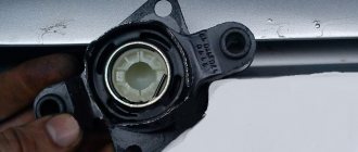
Where is the camshaft sensor located on the VAZ 2114?
The device is installed on power units of a VAZ-2114 car with 8 and 16 valves. The controller is located directly next to the camshaft and operates on the principle of a Hall sensor.
There is a special gear installed on the motor shaft, which is missing two teeth. The controller in question reads information directly from the engine shaft when the piston is located at top or bottom dead center. The need to use the device is due to changes in the ignition angle. The phase sensor data is sent to the electronic control unit. In turn, the ECU (if necessary) changes the ignition angle. Carburetor engines use a mechanical ignition advance system. Therefore, a phase controller is not installed on such models.
Thanks to the functions of the phase sensor, the vehicle receives two important advantages:
- the power unit is used more efficiently;
- fuel consumption is reduced.
Purpose of the DPRV
Such a device is based on the electromagnetic principle of operation and is used to carry out commands from the vehicle control and testing complex. The importance of the device parameters lies in the fact that without them there is no way to synchronize the car’s ignition system and the correct operation of the engine injectors, i.e. set the desired concentration of the air-droplet mixture supplied to the engine cylinders. Finding this sensor is easy. It is located on the high tide near the generator drive pulley.
During operation of the VAZ 2110 camshaft sensor, the price of which is acceptable for Russian motorists, the following problems may arise:
- During operation of the vehicle, dust and mud deposits remain on the product, falling onto it from the timing belt. This is facilitated by oil leakage from the over-valve cover of the power unit. These deposits on the camshaft sensor can lead to difficulties when starting the vehicle, low-power acceleration, low engine speeds that cannot be gained when the tachometer “gives” no more than 3.5 thousand rpm. In this case, the emergency device goes off, the on-board electronic device displays an error for some time, and then classifies it as a malfunction of the camshaft sensor, which in itself is nonsense, because With such a defect, starting the engine is absolutely impossible. If the product fails while driving, the car functions, but after stopping and turning off the engine, it is not possible to start it. If the engine continues to function, the camshaft sensor is working properly, so the defect should be looked for elsewhere.
- The vehicle is moving normally. The electronic device of the car begins to signal about product defects; to stop the receipt of erroneous signals from the detector, you should check the fastening of the wiring in the power compartment. Vibration friction during vehicle movement can cause the absence or weakening of one of the contacts. Additionally, you should sand the battery terminal from suspected oxidation and test the wire connections from the product to the on-board electronic device (front panel).
- The car does not start, attempts to revive the vehicle's engine do not lead to success. To solve this problem, you need to test the electrical wiring and its attachment to the contacts. Check the contact of the sensor with the collector, otherwise the product may fail.
How to determine the malfunction of the phase sensor on a VAZ-2114 car: preparatory work
As a result of the failure of the camshaft position sensor, unstable operation of the power unit at idle occurs. Typically, a motorist notices a “triple” of the engine, as well as an increase in fuel consumption. The reason for this phenomenon is the lack of information regarding ignition timing. As noted, such information is sent to the electronic control unit. The lack of data leads to the on-board computer starting emergency operation. That is, the power unit continues to function, but without making adjustments, but according to the established program. The malfunction of the node in question is indicated by errors, which are indicated by codes 0340 or 0343.
If a motorist notices the first signs indicating a sensor failure, it is necessary to inspect the system. Even a visual inspection allows you to determine the main causes of failure.
The driver needs to pay attention to the following details:
- inspect the surface of the case in order to identify external damage. The reason may be mechanical failures;
- check the phase sensor contacts. Sometimes moisture appears on the contacts, which leads to a short circuit;
- oxidation of contacts. Another fairly common reason that prevents reliable signals from being sent to the electronic control unit;
- Damage to electrical wiring. The cause of failure may be breaks or other damage to the wires.
Causes of malfunction
The main reason for the malfunction of the phase sensor is its natural wear, which occurs over time for any part. In particular, due to exposure to high temperatures from the engine and constant vibration in the sensor housing, its contacts are damaged, the permanent magnet may demagnetize, and the housing itself may be damaged.
Another main cause is problems with the sensor wiring. In particular, the power/signal wires may be broken, which is why no supply voltage is supplied to the phase sensor, or a signal does not come from it via the signal wire. It is also possible for the mechanical fastening on the “chip” (the so-called “ear”) to break. Less often, a fuse that is responsible, among other things, for powering the phase sensor may fail (for each specific car it will depend on the complete electrical circuit of the car).
Replacing the phase sensor on a VAZ-2114 car
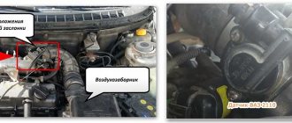
The scheme of work for replacing the controller on 8-valve and 16-valve power units is slightly different. Therefore, we will consider both options separately. First, let's focus on the 8-valve engine. Replacing the device involves performing the following steps:
- First you need to find the location of the phase sensor. It is located on the top of the power unit, near the air filter;
- The controller is secured with a bolt. To unscrew, you must use a 10mm wrench;
- after unscrewing the fasteners, it is necessary to remove the device;
- It is recommended to cover the controller connection socket. This is necessary to prevent moisture and debris from getting inside. This will also ensure the normal functioning of the new camshaft sensor;
- Next, you need to inspect the device for damage. Dirt must be removed with a dry cloth. After cleaning, you need to put the device back in place and check the functionality of the system. If error codes 0340 or 0 343 appear on the monitor, a replacement must be performed.
Sometimes even replacing the controller does not solve the problem. Such situations are rather the exception. However, they do occur and are caused by a shift in the control gear.
To detect a malfunction, you will need to use specialized equipment. Therefore, it will not be possible to solve the problem on your own in the garage. Another problem can be caused by improper installation of the timing belt. Also, the controller will not function if the timing belt is overstretched.
Mass air flow sensor model 21083-1130010-01
Design of mass air flow sensor (MAF) type 21083-1130010-01
The engine control system uses a hot-wire mass air flow sensor (MAF). It is located between the air filter and the intake pipe hose.
The mass air flow sensor pulse is a direct current voltage, the size of which depends on the volume and direction of air movement passing through the mass air flow sensor. With a forward air flow, the voltage of the sensor output signal changes in the range of 1...5 V. With a reverse air flow, the voltage of the sensor output pulse changes in the range of 0...1 V. The diagnostic device reads the sensor readings as air flow in kilograms per hour.
When a breakdown of the mass air flow sensor circuit occurs, the ECU stores its code in its memory and turns on the warning light. In this case, the ECU calculates the mass air flow value based on the crankshaft speed and throttle position.
Connection diagram for mass air flow sensor (MAF) VAZ 2114, 2113, 2115 type 21083-1130010
Installation location of the mass air flow sensor (MAF)
Detailed information about the mass air flow sensor is located on the page of this site called DMRV 2114, 2113, 2115 8 valves
Built-in air temperature sensor in the mass air flow sensor
The air temperature sensor is built into the air flow sensor. The sensitive element is a thermistor (a resistor that changes resistance depending on temperature) mounted in the air flow. The output pulse of the DTV ECU connected to the con is a direct current voltage in the range 0...5 V, the size of which depends on the temperature of the air passing through the sensor.
When a malfunction occurs in the DTV circuit, the controller stores its code in its memory and turns on the alarm. In this case, the ECU replaces the sensor readings with a fixed air temperature value of 33 oC.
| Table of dependence of DTV resistance on intake air temperature (±10%) | |
| Air temperature, oС | Resistance, kOhm |
| — 40 | 39,2 |
| — 30 | 23 |
| — 20 | 13,9 |
| — 10 | 8,6 |
| 0 | 5,5 |
| + 10 | 3,6 |
| + 20 | 2,4 |
| + 30 | 1,7 |
| + 40 | 1,2 |
| + 50 | 0,84 |
| + 60 | 0,6 |
| + 70 | 0,45 |
| + 80 | 0,34 |
| + 90 | 0,26 |
| + 100 | 0,2 |
| + 110 | 0,16 |
| + 120 | 0,13 |
Camshaft Sensor Replacement: 16-Valve Powertrain
If the driver operates an engine with 16 valves, then the procedure for removing and replacing a failed sensor will be performed as follows:
- the controller is located next to the first camshaft pulley, directly under the air manifold;
- first you need to dismantle the radiator grille; using a 10mm wrench, unscrew the two fasteners;
- inspection of the controller, cleaning the surface, studying the condition of contacts and wiring;
- If the device is not suitable for use, you need to install a new device.
When replacing the phase sensor, it is not recommended to use special compounds that provide sealing and tightness. The motorist must understand that the controller is constantly exposed to elevated temperatures. Therefore, sealants and other means can lead to failure of the oil system, and this also applies to the power unit.
When studying the VAZ 2114 camshaft sensor signs of malfunction , it should be noted that in case of problems, the check engine lamp should light up on the screen.
This will indicate that the electronic control unit is waiting for information from the phase controller.
As a result of the fact that no data is received, the ECU switches to emergency mode and reads information from the crankshaft position sensor. Therefore, unstable engine operation at idle occurs, as well as increased fuel consumption.
Checking system functionality
If a new sensor is installed, then all the work is done and you can enjoy a comfortable ride. Obviously, all the work on replacing a phase sensor comes down to finding it, and replacement takes half an hour. But dismantling the old device and installing a new device is not enough. The car owner needs to make sure that the controller sends a reliable signal to the on-board computer. To do this, you need to perform a number of checks:
- connect the battery;
- start the power unit;
- using a scanner, check the system for error codes;
- listen to the engine. The power unit should not triple;
- There should be no check engine light on the dashboard.
If the phase sensor is replaced on 16-valve engines, then you will need to spend a little more time. In general, the entire repair procedure takes no more than half an hour. If all the work is done by hand, then the cost items come down to the purchase of a new phase sensor, which costs several hundred rubles.
When visiting a service station, a motorist must have at least 1,000 rubles with him, which he will have to pay for the work. In any case, each motorist decides for himself whether to do the work with his own hands or turn to specialists. As noted, it is impossible to do without the intervention of a car service technician if there is a shift in the pressed gear. This defect can only be eliminated using special equipment.
Replacement procedure
If checks show that your element no longer performs its previous functions, you will have to replace it with a new one. This is done quite simply.
Unscrew
You need to follow the sequence of actions, which will allow you to carry out the replacement yourself without unnecessary problems and financial costs.
- Remove the distributor from your car and remove its cover.
- Remove the slider. To do this, you need to pull it up a little.
- Remove the black cover. On the VAZ 2110 it is usually made of plastic.
- Remove the bolt that holds the plug.
- Remove the plug itself.
- Unscrew the mounting bolts that hold the hall sensor plate.
- Remove the fasteners securing the vacuum manifold.
- Remove the retaining ring.
- Remove the rod and corrector from the structure.
- Next you will find a clamp that needs to be pulled apart to remove the wires.
- Now the support plate is removed.
- Two bolts hold the hall sensor. They need to be unscrewed, which will allow you to remove the meter and put a new one in its place. Perform the assembly procedure strictly in the reverse order of dismantling.
If you find primary signs of a malfunction, we strongly do not recommend delaying repairs. Complete the check as quickly as possible.
If the check shows that the meter is faulty, follow the procedure for dismantling it, and also select a quality spare part.
Changing the sensor
If you realize that the camshaft position device has failed on an 8- or 16-valve VAZ 2110 engine, then you have no choice but to replace it. In any case, starting the engine will be impossible.
How to perform the replacement yourself?
To replace the camshaft position sensor on a VAZ 2110 with an 8 or 16 valve engine, you need to find out where it is located. Open the hood of your VAZ. This part is located to the right of the filler neck for engine fluid.
- Initially, you should disconnect the power cable harness. To do this, move the plastic retainer aside and pull the plug.
- Then, using a ratchet and a socket, unscrew the screw that secures the camshaft pulley position sensor.
- Remove it from its installation location.
- Check the marking numbers before directly installing the sensor. They must match on the dismantled device and on the one you are going to install.
- Install the new camshaft position sensor by reassembling it in reverse order.
Speed sensor type 2111-3843010-00
Design of the speed sensor VAZ 2114, 2113, 2115 models 2111-3843010-00
What is a speed sensor used for?
The speed sensor of a VAZ 2114, 2113, 2115 passenger car produces a pulse signal that informs the ECU about the vehicle's driving speed. DSA installed on the gearbox
When the drive wheels rotate, the speed sensor generates six pulses per meter of vehicle movement. The ECU determines the speed of the vehicle based on the pulse repetition rate.
If the DSA circuits malfunction, the controller stores its code in its memory and turns on the alarm.
Speed sensor installation location
Speed sensor connection diagram
Speed sensor terminal pinout
The pinout of the speed sensor connector terminals has the following designations:
- From the main relay - plus (“+”);
- Signal output to ECU;
- Mass - minus (“-“).
Signs of device failure
A faulty phase sensor will result in signal disruption. The ECM polls the DF for 4-5 minutes. If the signal does not appear within the specified period, the unit switches to double fuel injection mode.
If the phase indicator fails, the controller queries only the crankshaft position sensor. In this case, gasoline is supplied simultaneously to two cylinders. At the same time, fuel consumption increases by approximately 10%.
Failure of the phase sensor leads to a number of other troubles. Repairs need to be made. Signs of engine trouble:
- Increased gasoline consumption.
- Vehicle diagnostic failures.
- Violation of acceleration dynamics of VAZ 2115.
- Difficult start. The engine starts after 4-5 seconds.
- After starting, the Check Engine light comes on.
- Error P0343 or 0340 appears during diagnostics.
Before inspecting the sensor, you should make sure that the remaining parts are in good condition. Failures will occur due to a broken timing belt, loose camshaft gear, or incorrect installation of marks.
Often sensor error 0343 is associated with oxidation of contacts or broken wires. Before discarding the phase indicator, make sure the wiring is intact. Resistance measurements in the circuit are carried out with a multimeter.
It is difficult to determine the malfunction of the phase sensor yourself. It is better to carry out diagnostics at a service station. The sensor is checked on a computer.
If the auto mechanic makes a disappointing diagnosis, then we go to the store. You should know that you can run into low-quality spare parts or fakes. Experts advise purchasing sensors from Bosch or the Kaluga plant.
The phase sensors for 8- and 16-valve engines are different. Therefore, when purchasing, tell the seller your engine type. The best option would be to go to the car market with your original. If after replacement the sensor error occurs again, return it.