The transmission of the VAZ-2101 car consists of a manual gearbox, which transmits torque to the rear axle through a driveshaft. The gearbox itself is mechanical, 4-speed (4 forward gears and 1 reverse), three-way, with manual control (gear shifting is performed by the driver using a lever located in the car's interior). At the time of the release of the VAZ-2101, this type of gearbox was one of the highest priorities, since it ensured the least losses.
To ensure that the car moves at different speeds, each gear had its own gear ratios, which decreased as the gearbox gear increased. So, the first gear has a gear ratio of 3.753, the second – 2.303, the third – 1.493, the fourth – 1.0. The rear gear has the highest gear ratio - 3.867. The changing gear ratios of the VAZ-2101 gearbox allowed the car to move at different speeds; in 1st gear a high traction force is provided, and in 4th gear the maximum possible speed is provided.
To reduce operating noise, all gears involved in forward movement have oblique teeth, while the gears of the rear stage have straight teeth.
To make it easy to control the gearbox and change gears with minimal impact, the forward gears are equipped with synchronizers.
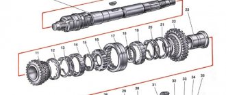
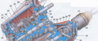
The cross-sectional diagram of the VAZ-2101 gearbox is presented below (PV - primary shaft, BB - secondary, PrV - intermediate, ZX - reverse):
| 1 – gearbox pan; 2 – plug for the hole for controlling the amount of gearbox lubricant; 3 – gear of the 2nd stage PrV; 4 – gear of the 3rd stage PrV; 5 – PrV with a set of gears; 6 — bearing PrV (front); 7 – thrust bolt; 8 – washer; 9 – PrV gear (with constant clutch); 10 – synchronizer washer for the 4th stage of the PV; 11 – input shaft; 12 – crankcase front cover; 13 – oil seal; 14 – bearing PV (rear); 15 – clutch housing; 16 – housing 17 – breather of the crankcase ventilation system; 18 – PV gear (with constant clutch); 19 – explosive bearing (front); 20 – 4th stage synchronizer ring; 21 – synchronizer clutch of the 3rd and 4th stages; 22 – 3rd stage synchronizer ring; 23 – 3rd stage synchronizer spring; 24 – gear of the 3rd stage of the explosive; 25 – gear of the 2nd stage of the explosive; 26 – hub of the synchronizer clutch of the 1st and 2nd stages; 27 – secondary shaft; 28 – gear of the 1st stage of the explosive; | 29 – bushing; 30 – BB bearing (intermediate); 31 – gear ZH BB; 32 – lever rod; 33 – pillow; 34 – bushing; 35,36 – bushings (remote, shut-off); 37 — boot (external); 38 – boot (internal); 39 – lever support washer (spherical); 40 – gearshift lever; 41 – explosive seal (rear); 42 — cardan coupling flange; 43 – BB nut; 44 – seal; 45 – ring; 46 – BB bearing (rear); 47 – odometer gear; 48 – odometer drive; 49 – gearbox housing cover (rear); 50 – 3X fork; 51 – gear 3X (intermediate); 52 – gear ZH PrV; 53 – axis of the intermediate gear ZH; 54 – gear of the 1st stage PrV; 55 – magnet; 56 – plug 1 – gearbox pan; |
Link on topic:
Design, diagram and description of malfunctions of the ignition switch VAZ 2101
VAZ 2110 gearbox diagram:
| 1 – clutch release bearing; | 18 – driven gear of the second gear of the secondary shaft; |
| 2 – guide sleeve of the clutch release bearing; | 19 – driven gear of the third gear of the secondary shaft; |
| 3 – main gear drive gear; | 20 – synchronizer for 3rd and 4th gears; |
| 4 – roller bearing of the secondary shaft; | 21 – driven gear of the fourth gear of the secondary shaft; |
| 5 – oil sump; | 22 – ball bearing of the secondary shaft; |
| 6 – satellite axis; | 23 – driven gear V of the secondary shaft transmission; |
| 7 – speedometer drive drive gear; | 24 – 5th gear synchronizer; |
| 8 – axle gear; | 25 – secondary shaft; |
| 9 – differential box; | 26 – rear cover of the gearbox housing; |
| 10 – satellite; | 27 – drive gear of 5th gear; |
| 11 – clutch housing; | 28 – ball bearing of the input shaft; |
| 12 – driven gear of the main gear; | 29 – input shaft; |
| 13 – adjusting ring; | 30 – gearbox housing; |
| 14 – tapered roller bearing of the differential; | 31 – roller bearing of the input shaft; |
| 15 – axle shaft seal; | 32 – input shaft oil seal; |
| 16 – driven gear of the 1st gear of the secondary shaft; | 33 – breather. |
| 17 – synchronizer of 1st and 2nd gears; |
The operating scheme is as follows: the input shaft (29) is made in the form of a block of drive gears, which are in constant engagement with the driven gears of all forward gears. The secondary shaft (25) is hollow, with a removable drive gear (3) of the main gear. On the secondary shaft there are driven gears (16, 18, 19, 21, 23) and synchronizers (17, 20, 24) for forward gears. The front bearings (4, 31) of the shafts are roller, the rear bearings (22, 28) are ball. An oil sump (5) is located under the front bearing of the secondary shaft, directing the flow of oil into the secondary shaft and further under the driven gears.
The differential is two-satellite. The preload in the differential bearings is adjusted by selecting the thickness of the ring (13). The driven gear (12) of the main gear is attached to the differential box flange.
Problems
Often, VAZ 2110 owners voice a problem regarding the switching or departure of first gear. Most likely, the reasons lie in the following:
- synchronizer problems;
- damage to the retainer spring when the lever dangles and the gears are switched on randomly;
- damaged rod and fork.
A common problem is when the second gear is reluctantly engaged, or it is simply knocked out. The most likely causes of the problem:
- poor engagement of the gear and clutch that engages the gears;
- wear of gear teeth and coupling;
- problems with the clutch.
Gear shift drive diagram:
| 1 – gear selection rod lever; | 10 – hinge bushing; |
| 2 – gear selection lever; | 11 – hinge tip; |
| 3 – gearbox housing; | 12 – clamp; |
| 4 – clutch housing; | 13 – protective cover of traction; |
| 5 – gear selection rod; | 14 – gearbox control drive rod; |
| 6 – rod bushing; | 15 – gear shift lever; |
| 7 – rod seal; | 16 – ball joint cage; |
| 8 – protective cover; | 17 – ball joint of the gear shift lever; |
| 9 – hinge body; | 18 – jet thrust. |
The gearbox control drive consists of a gear shift lever (15), a ball joint (17), a rod (14), a gear selection rod (5) and gear selection and shift mechanisms (crumpled “P”).
To prevent spontaneous switching off of the P due to the axial movement of the power unit on its supports when the vehicle is moving, a reaction rod (18) is introduced into the gearbox control drive, one end of which is connected to the power unit, and a clip (16) of the ball joint of the lever (15) is attached to the other end ) switching P.
A lever (1) is attached to the inner end of the rod (5), which acts on the three-year lever (2) of the P selection mechanism. This mechanism is made as a separate unit and is attached to the plane of the clutch housing.
How to remove and install a manual transmission
The procedure for removing the gearbox must be carried out by driving the car onto an overpass or into a garage with an inspection hole. The wider and more spacious the pit, the easier it will be to do the work. Provide good lighting for the underside of the car, because all work will take place in semi-darkness.
The gearbox in the “ten” weighs about 30 kg, provided that the oil is drained. The weight does not seem very large, but keep in mind that you will need to hold the gearbox and unscrew the nuts. There are two options: work with an assistant or build a device into which you can rest the box when removing it and then grab it with both hands to remove it.
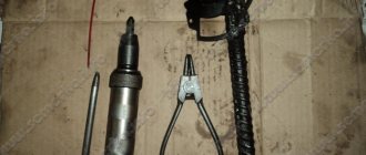
List of tools required for dismantling:
- Set of wrenches;
- Set of socket heads with extension;
- Flat and figured screwdrivers;
- Pliers;
- Mount;
- Jack;
- Clean dry cloth for wiping.
Further work is carried out in the following order:
- Remove the plastic engine protection by unscrewing the bolts with a socket wrench. We also remove the shield covering the engine compartment.
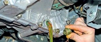
- Drain the oil from the box. Any container is suitable for this, for example, a plastic 5-liter bottle with a cut off neck. We unscrew the plug, wait until everything drains, then wipe the plug and drain neck and tighten the hole.
- We de-energize the car by removing the terminal from the battery
- Remove the air filter along with the throttle valve. We also remove the air flow sensor and crankcase ventilation hoses.
- We remove the starter. To do this, you need to remove all the rubber caps from the large bolt with the plus from the battery and the small bolt of the solenoid relay, disconnect all the terminals, and then unscrew the bolts securing the starter to the engine housing.
- We remove the clutch cable by releasing it from the fork and loosening the outer nut.
- We disconnect the wiring from the box - this is the speed indicator sensor and the reverse gear lights.
- You can remove the reaction thrust by unscrewing the two nuts holding the bracket to the buffer.
- Disconnect the gear shift rod from the joint
- Next, you need to unscrew the bolts on the clutch housing cover and move the cover to the side.
- The next step is to remove the right and left front wheel drives. You can insert a plug into the hole of one of the drives so as not to mix them up during assembly. We remove the left drive completely, move the right one to the side so that it does not interfere. The bolts that secure the ball joint must be loosened.
- Then we remove the lower crankcase cover and unscrew the lower bolt that secures the gearbox to the engine.
- After this, the engine must be lifted to free the box for removal. You can throw a cable with a hook over the ceiling beam. A handy option is to use a strong board as a support.
- The next step is to remove the rear power unit mount. First you need to unscrew the bolt holding the engine to the left side support, then unscrew the bolts securing the rear support to the body and gearbox. Hold the bolt heads with a second wrench, otherwise they will turn. After this, you can remove the support itself.
- The box must be removed from the guides while holding it in weight. To obtain a good breaking force, you can insert a flathead screwdriver between the cylinder block and the clutch housing. The input shaft gears should disengage. If this does not happen, slightly shake the engine by pressing it with a stop board.
- Be careful! The heavy body of the box should not rest on anything. Moving it back as far as possible, tilt the assembly with its front edge forward and pull it out from under the car.
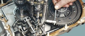
After removing the box, it should be disassembled to carry out a visual inspection of the shafts and gears. If necessary, replace worn parts with new ones
When assembling the box, pay special attention to sealing the crankcase and replacing the seals
Reinstallation of the box is carried out in the reverse order. If this is your first time carrying out a similar procedure, take photographs of each step, the location of parts and fasteners. This will help restore the sequence of actions.
Video: dismantling the gearbox on Lada 2110
After repairing the gearbox, you need to run in the new gears for some time, especially if you changed them block by block, in groups. During the break-in period, refrain from aggressive driving style. When switching to a higher speed, pause for one or two seconds, and when downshifting, on the contrary, engage a new one immediately. Always monitor the oil level - if it drops, take the time to crawl under the car and inspect for leaks at the junction of the cover and crankcase. Handle your vehicle carefully and the service life of the gearbox will increase.
Gear selection mechanism:
| 1 – gear selection lever (forward); | 6 – reverse fork axis; |
| 2 – guide axis of locking brackets; | 7 – locking bracket; |
| 3 – axis of the gear selection lever; | 8 – reverse fork; |
| 4 – spring; | 9 – gear selection lever (reverse); |
| 5 – retaining ring; | 10 – housing of the gear selection mechanism. |
Two axles are mounted in the housing (10) of the gear selection mechanism. A three-year-old gear selector lever and two locking brackets (7 and 12) are installed on the axis (3). The other axis (2) passes through the holes of the locking brackets, securing them from turning. The gear selector lever arm (1) is used to engage P forward gear, the lever arm (9) is used to engage reverse gear, and the third arm is used by the gear selector rod lever. A fork (8) for engaging reverse gear is installed on the axle (6).
Oil is poured into the gearbox of a VAZ 2110, the level of which should be between the control marks of the oil level indicator.
Like any car, the VAZ 2110 also has a gear shift mechanism. The VAZ gearbox is five-speed, activated by a lever located in the car's interior.
In order to be able to fix problems yourself, you need to understand a little about how exactly the switching mechanism works, which is why there are cases when some speed does not turn on or goes out. And also know how to fix it on your own.
Features of mechanical devices
Dismantling or removing the device is the first step for those who decide to repair the gearbox themselves. It is advisable to have an assistant nearby, it will be much easier.
First, the battery is removed from the car, then they move on to the starter. Replacing the backstage on your own is carried out in the same way, there are only minor differences. Repairing the secondary shaft requires approximately the same actions. The cable responsible for the clutch must be disconnected from the fork. The device has a special bracket from which the part is pulled out.
Any reference book on gearbox repair at home will tell you about this.
Repairing the gearbox linkage is also not complete without this. First you need to compress the required number of spring-type clamps, after which the part with the block is dismantled. There are several bolts responsible for the connection between the torque rod and the box. They need to be unscrewed using a key with the appropriate parameters. How and when the gearbox drive shaft is repaired is indicated in the VAZ 2110 operating manual.
Gearbox shifter for VAZ 2110.
At the next stage, a major overhaul requires the removal of the wheel drives. The main thing is that there is a plug left there. The ball joint structure, which is located on the left side, is turned away from the fist.
Repair of the gearshift knob is carried out separately, if necessary. The instructions are easy to find.
The ball joints can be left in place, but unscrewing them makes the job faster and easier. The engine, for its part, is equipped with only one mount. Therefore, repairing a lever and other similar processes only require unscrewing one nut at a given moment. Sometimes it is necessary to remove the hose responsible for injection from the stud. The repair manual says that the box itself moves as far back as possible.
Checkpoint diagram
The gearbox design is as follows:
- To ensure gear shifting, the gearbox contains a primary shaft consisting of a gear block. They are constantly engaged with the drive gears from the first to the fifth speed (that is, those that are oriented towards driving forward);
- The secondary shaft is equipped with a drive gear for the main transmission, and it also has gear synchronizers that ensure forward movement of the driven gears. There are also bearings plus an oil sump;
- VAZ two-satellite differential, with the driven gear of the main gear attached to the flange of its box;
- the gearbox drive consists of a gear shift knob, a ball joint, a selector rod, a rod, gear selection mechanisms, and gear shifting mechanisms;
- Jet thrust is designed to protect the gearbox from flying out of gear. Its ends are attached to the support and the power unit.
Gear shift drive diagram
A short summary
General structure of manual gearboxes on VAZ
VAZ manual gearboxes are very reliable, unpretentious gearboxes, their gearshift scheme is the most standard, no exotic ones. And this is a huge plus, since their maintenance and repair are just as simple and straightforward. They have to be repaired relatively rarely, since they perfectly hold the torque from the ring shaft of VAZ engines, even forced ones. For comparison, many manual gearboxes have difficulty maintaining the torque of stock engines, comparable in power to VAZ ones, and very quickly fail at the slightest increase in engine power. What makes VAZ manual transmissions so durable? Let's look at the diagram of their design and understand why they are good and what their shortcomings are.
Adjustment
On a VAZ 2110, it is not so uncommon for the gears to shift poorly or get knocked out. A mechanism for adjusting the speed selection drive is provided specifically for this purpose.
Adjustment may be necessary if:
- the box was recently removed for repairs;
- one of the gears falls out;
- the speeds do not engage well or simply get knocked out when the car is moving.
If you have one of these problems, try making adjustments first. Its sequence:
- Under the bottom of the VAZ 2110, find and slightly loosen the nut on the bolt that tightens the clamp that secures the rod designed to control the gearbox;
- Use a screwdriver to slightly move apart the grooves in the end of the rod and the resulting gap on the clamp itself. This is necessary to ensure easy movement of the rod in relation to the gear selection rod. Place the rod in the neutral position;
- Release the shift knob from the cover in the cabin;
- Align the lever using a special template. This is done like this: install a template in the window of the rear speed lock bracket lining. After this, insert the lever axis stop into the groove of the template, pressing it without unnecessary force in the transverse direction;
- Then adjust the axial play of the rod in the rear direction, and its axial play by turning to the left;
- Install the clamp, not reaching a few millimeters from the end of the rod. Then tighten the clamp thoroughly with the bolt.
Installation of the backstage from "Kalina"
Replacing the VAZ 2110 gearbox
On a VAZ 2110 you can successfully install a slide from Kalina:
- To do this, it needs to be modified a little.
- The cardan from the new model is 20 mm longer than the original “tenth”.
- Therefore, it needs to be cut, to do this, use a lathe.
- The replacement of the slide must be carried out in the garage from the inspection hole.
- Remove the plastic tunnel from the car interior.
- Also remove the boot.
- Remove the old rocker, unscrew all the fasteners from under the bottom of the car.
- Install a new link and adjust it.
Why is it recommended to install a cardan from the new Kalina? On VAZ-2110 models, universal joints made of less resistant material are installed, so they quickly fail. This causes premature play in the rocker, which usually affects the quality of gear shifting while the vehicle is moving. After purchasing a new link, a visual comparison should be made of the old cardan and the purchased one. The comparison will be entirely in favor of the new acquisition. The Kalina cardan is made of better quality material, it is much more wear-resistant.
Gearbox slides for VAZ 2110
After installing a new link, the lever may rattle. Since this link completely eliminates play, that is, the vibration is transmitted completely to the lever.
Fixing lever rattling
- To do this, install a new ball joint for the lever and install a repair kit.
- The ball joint must be replaced from the inspection hole, since it is easier to change it from under the bottom of the car.
- Install the retaining spring to the gear lever.
It will dampen vibration by holding the lever in the desired position. This will not affect the application of additional forces when turning on the speeds. To get rid of the rattling of the lever, you can install additional plastic washers on the gearbox axle. To do this you will need:
- material - plastic (regular lid for jars);
- open-end wrench No. 10, No. 13;
- scissors;
- Phillips screwdriver;
- flat file, you can use a small flat file.
CPT diseases
VAZ 2110 owners often complain that the first gear is difficult to engage or crashes.
- often the synchronizer is to blame;
- perhaps the clamp spring has burst, the lever is hanging loose, the speeds are switched on as desired;
- The stem and fork may need replacement.
Another complaint is that second gear is difficult to engage and often gets knocked out.
Here you can suspect the main culprits:
- the second one flies out most often because the gear teeth do not mesh well with the clutch that turns on the speeds;
- The tips of the gear teeth and clutch are already worn out, so the speed is difficult to engage. If you don’t intervene, it will soon fly out;
- as an option, when it knocks out on bumps, the clutch dies.
Sometimes (albeit rarely) when the second one does not turn on well enough and falls out, replacing the retaining spring helps. If the speeds often drop out, some of them are difficult to turn on, which means that half-measures will no longer help - the box needs to be overhauled.
Whether you do it yourself, or go to a service center where they will repair it for you and also adjust the gear shift mechanism, decide for yourself, based on your own experience and skills.
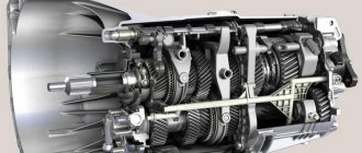
Cross-sectional design of a gearbox on a VAZ 2110
Main parts of the VAZ 2110 gearbox: 1 – rear cover of the gearbox housing, 2 – fifth gear drive gear, 3 – input shaft ball bearing, 4 – fourth gear drive gear of the input shaft, 5 – input shaft, 6 – third gear drive gear input shaft, 7 – gearbox housing, 8 – drive gear of the second gear of the primary shaft, 9 – reverse gear, 10 – intermediate reverse gear, 11 – drive gear of the first gear of the primary shaft, 12 – roller bearing of the input shaft, 13 – oil seal input shaft, 14 – breather, 15 – clutch release bearing, 16 – clutch release bearing clutch guide sleeve, 17 – main drive drive gear, 18 – secondary shaft roller bearing, 19 – oil sump, 20 – pinion axis, 21 – drive drive gear speedometer, 22 – axle gear, 23 – differential box, 24 – satellite, 25 – clutch housing, 26 – oil drain plug, 27 – main drive driven gear, 28 – adjusting ring, 29 – differential tapered roller bearing, 30 – oil seal axle shaft, 31 – driven gear of the first gear of the secondary shaft, 32 – synchronizer of the first and second gears, 33 – driven gear of the second gear of the secondary shaft, 34 – driven gear of the third gear of the secondary shaft, 35 – synchronizer of the third and fourth gears, 36 – driven gear of the fourth transmission of the secondary shaft, 37 – ball bearing of the secondary shaft, 38 – driven gear of the fifth gear of the secondary shaft, 39 – fifth gear synchronizer, 40 – secondary shaft.
Gearbox control drive VAZ 2110
VAZ 2110 backstage diagram: 1 – protective cover of the rod, 2 – gearbox control rod, 3 – gear shift lever, 4 – pin of the spherical gear shift lever, 5 – ball joint cage, 6 – ball joint of the gear shift lever, 7 – buffer , 8 – spring, 9 – reaction rod, 10 – gear selection rod lever, 11 – gear selection lever, 12 – gearbox housing, 13 – clutch housing, 14 – gear selection rod, 15 – rod bushing, 16 – rod seal, 17 – protective cover, 18 – hinge body, 19 – hinge bushing, 20 – hinge tip, 21 – clamp.
The principle of operation of the VAZ 2110 gearbox
The gearbox is mechanical, two-shaft, with five forward gears and one reverse gear, with synchronizers in all forward gears. It is structurally combined with the differential and main gear.
The gearbox housing consists of three parts (cast from aluminum alloy): the clutch housing, the VAZ 2110 gearbox housing and the rear cover of the gearbox housing. During assembly, a gasoline-oil-resistant gasket sealant (for example, KLT-75TM or TB-1215) is applied between them. There is a special magnet in the crankcase socket that retains metal wear products.
The input shaft of the VAZ 2110 is designed as a block of drive gears, which are in constant engagement with the driven gears of all forward gears. The secondary shaft of the VAZ 2110 is hollow (for supplying oil to the driven gears), with a removable drive gear of the main gear. It houses the driven gears and forward gear synchronizers. The front shaft bearings are roller, the rear are ball. The radial clearance in roller bearings should not exceed 0.07 mm, in ball bearings - 0.04 mm. An oil sump is located under the front bearing of the secondary shaft, directing the flow of oil into the shaft.
The differential is two-satellite. The preload in the bearings (0.25 mm) is adjusted by selecting the thickness of the ring installed in the gearbox housing housing under the outer ring of the differential bearing. The main drive driven gear is attached to the differential box flange.
The gearbox control drive consists of a gear shift lever, a ball joint, a rod, a gear selection rod and gear selection and shift mechanisms. TB-1324 thread glue is applied to the screws securing the rod and lever to the gear selector rod before assembly. The lever and hinge mounting screws vary in length, coating and tightening torques. The lever fastening screw is phosphated (dark color), 19.5 mm long, tightened with a torque of 3.4 kgf.m. The hinge fastening screw is cadmium-plated (golden), 24 mm long, tightened with a torque of 1.95 kgf.m. LSC-15 lubricant is placed in the ball joint before assembly.
To prevent the gears from spontaneously switching off due to the axial movement of the power unit when the vehicle is moving, a reaction rod is introduced into the gearbox control drive, one end of which is connected to the power unit, and a ball joint race for the gear shift lever is attached to the other end.
A lever is attached to the inner end of the rod, which acts on the three-arm lever of the gear selection mechanism. This mechanism is made as a separate unit and is attached to the plane of the clutch housing.
The housing of the gear selection mechanism of the VAZ 2110 has two axes. One has a three-arm gear selector lever and two locking brackets. The other axis passes through the holes of the locking brackets, securing them from turning. One arm of the gear selection lever is used to engage forward gears, the other is used to engage reverse gear, and the third arm is used by the gear selection rod lever. A reverse fork is installed on the axle.
The gearbox is filled with TM-5-9p oil at the factory, designed for 75,000 km. The oil level in the VAZ 2110 gearbox should be between the control marks on the oil level indicator.
“>
selection of differential bearing adjusting ring
Differential bearings must be mounted with a preload of 0.25 mm (for control 0.15-0.35 mm). The tension is ensured by selecting the thickness of the adjusting ring 13 (see Fig. 3-7), installed in the gearbox housing socket under the outer ring of the differential bearing.
Note.
Select the thickness of the adjusting ring when replacing one of the following parts: differential box, differential bearing and clutch or gearbox housings.
Determine the thickness of the adjusting ring using tool 67.7824.9517 in the following sequence: press the outer ring of the tapered roller bearing 3 together with the adjusting ring 4 (Fig. 3-24) into the gearbox housing;
Note.
The installation ring 4 has a constant thickness of 1.25 mm.
Press the outer race of the other differential bearing into the clutch housing. At the same time, be careful not to mix up the outer rings of the differential bearings; install the differential into the gearbox housing and, covering it with the clutch housing, tighten at least three nuts, equidistant from each other, securing the gearbox housing to the clutch housing (tightening torque 24.5 Nm (2.5 kgcm)). Then turn the differential to self-install the bearings 2-3 turns; install support mandrel 2 on the differential box and secure indicator 1 with extension using a universal holder. Install the indicator leg on the support mandrel with a preload of 1 mm, and in this position fix the indicator and set its arrow to zero; move the differential from below and watch the indicator;
WARNING
When measuring the axial movement of the differential, do not rotate it so as not to distort the measurement results.
Using the formula S = A + B + C, calculate the thickness of the adjusting ring of the differential bearings, where: S is the thickness of the adjusting ring; A is the amount of axial movement of the differential; B - the amount of preload of the differential bearings; C is the thickness of the installation ring (constant value). Example.
The indicator reading when moving the differential is 1.00 mm. The preload of the differential bearings is 0.25 mm, the thickness of the mounting ring is 1.25 mm. S = 1.00+ 0.25+ 1.25 = 2.50 mm. After determining the thickness of the adjusting ring, disconnect the clutch housing and gearbox, remove the differential, press out the outer bearing ring from the gearbox housing using a puller 67.7801.9526 and install the selected adjusting ring instead of the adjusting ring 4. Press in the outer ring of the differential bearing using the mandrel 67.7853.9575 and install the differential into the gearbox housing and, covering it with the clutch housing, tighten the nuts securing the gearbox to the clutch housing. Check the moment of resistance to rotation of the differential with a dynamometer 02.7812.9501. To do this, pass the tip of the dynamometer through the hole in the differential box (for the wheel drive shaft) until it wraps around the pinion axis. Turn the dynamometer handle several turns clockwise and use the scale to determine the moment of resistance to turning. It should be: for new bearings 147-343 Ncm (15-35 kgf.cm), for run-in bearings at least 30 Ncm (3 kgf.cm).
Something bad happened and a VAZ 2110 gearbox needed to be repaired. Unit repair is required when:
- It is difficult to switch gears off and on.
- automatic switching off of gears.
- noise occurs when shifting gears.
- transmission oil leak.
The reasons for the breakdown may be different, perhaps the oil was not changed in a timely manner or the mechanism has simply exhausted its resource.
How is a VAZ 2110 gearbox repaired? Do-it-yourself VAZ 2110 gearbox repair, video.
Changing the oil
According to the documentation, the lubricant component in VAZ 2110 engines and transmissions must be changed every 15 thousand kilometers or at least once a year.
So, we need to warm up the engine well and prepare the required oil and, preferably, a new oil filter, as well as the tools necessary for the job.
gearbox housing 2110
To drain the waste, you will need to unscrew the plug from the oil pan. Next, within 10-15 minutes, the oil is drained into a special container, which will need to be prepared in advance. Then the drain plug returns to its original position and is screwed tightly. Now you can replace the old oil filter with a new one (if necessary).
Now that the old oil has been drained, pay attention to its color and presence of inclusions. If the oil is dark brown in color and to the touch contains various types of inclusions such as metal dust or pieces of dirt, then the transmission will need to be flushed.
DON'T WASTE MONEY ON REPAINTING! Now you can remove any scratch from the body of your car in just 5 seconds.
For this purpose, special solutions are used, which are poured into the engine and gearbox before new oil. In this case, you will need to drive the car with such a solution for a short time and not quickly, five minutes along the garage will be enough, and then drain the mixture and the dirt that it has collected in the same way as described for the process of draining the “working off”.
In order to fill with fresh oil, you will need to remove the filler cap. In this case, from 3 to 4 liters of oil are poured into the engine, depending on the readings of the dipstick. Ideally, the oil level is between the min. marks. and max.
These marks are marked on the dipstick as the minimum and maximum values. Next, you will need to start the engine and wait until the oil light (or oil pressure light) goes out. After this, turn off the engine, check the oil level and, if necessary, remove excess or add more oil.
There are times when the light bulb just won't go off. In such cases, it is better to check the quality of the oil filter or replace it if it was not changed during the replacement process.