01/26/2022 8,051 VAZ 2101
Author: Ivan Baranov
All modern cars are equipped with hazard warning lights, which cannot be said about older cars. For example, in this article we will talk about the legendary Russian “Kopeyka” - VAZ 2101. Since these cars are not equipped with a warning light, car owners have to install it themselves. What is the wiring diagram for the emergency lights on the VAZ 2101 and how to correctly carry out this task - read on.
[Hide]
Installation of alarm systems on VAZ 2101 and their modifications
Installation of alarm systems on VAZ 2101 and their modifications.
I think that many people have had the desire to equip their car with an alarm system. After all, if anyone doesn’t know, the emergency warning system began to be installed on cars of the VAZ family starting with model 2103. But you must admit that sometimes you want to flash the emergency lights to the person who let you pass in a traffic jam, wink at a pretty girl, or simply, almost legally, stop at public transport stop in front of the trolleybus and run to the stall almost without violating traffic rules...
So, for those who are interested in all of the above...
First, I’ll tell you what materials and tools we will need to do this work.
1. Key 10. 2. Phillips screwdriver. 3. Wire cutters. 4. Pliers. 5. Flat screwdrivers. 6. Knife. 7. A lot of patience, because you will remember a certain MOTHER and VAZ designers more than once.
Materials and elements:
1. Electrical tape or heat shrink tubing. 2. Installation wire (about 5 meters). Preferably pieces of different colors. 3. Turn signal and hazard warning relay from VAZ 2106. (four contacts) 4. Hazard warning button. (six contacts) 5. Relay connector. 6. Connector for connecting a button.
Operating time: 2-3 hours at best
To begin with, we remove the torpedo, since VAZ designers at one time saved on wires and many, in length, are simply enough to connect a standard element. To do this, we perform the following actions:
1. Unscrew the fastening screws and remove the facing casing of the steering shaft and the lining of the windshield pillars. 2. Remove the instrument cluster. 3. Disconnecting the wires from the glove box lighting lamp, unscrew the screws securing the side of the glove box to the instrument panel, the screws securing the bottom of the glove box and remove it. 4. Remove the four screws that secure the instrument panel to the front cross member. Through the openings of the glove box and instrument cluster, unscrew the four nuts of the upper panel fastening to the front end. 5. Remove the handles from the heater control levers, to do this, at the junction of the handle with the lever, use a flat thin tool to bend the lower part of the upper handle, and the upper part of the lower one. 6. Disconnect the wires from the instrument lighting switches, dimensions and heater. 7. Remove the two screws securing the heater control levers. 8. Remove the instrument panel.
Installation of the instrument panel is carried out in the reverse order.
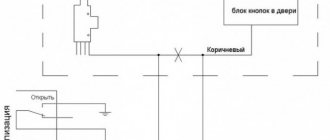
The turn signal breaker circuit for the VAZ 2101 and their modifications is as follows:
Symbols on the diagram:
1.Front direction indicators. 2. Turn signal repeaters on the front fenders. 3.Battery 4.Generator. 5. Ignition switch. 6. Fuse block. 7. Relay turn signal breaker. 8.Indicator lamp in the instrument cluster. 9. Steering column turn signal switch. 10. Direction indicators in the rear lights.
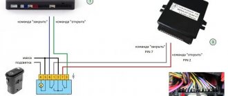
As a connection diagram, we use a diagram from a VAZ 2106 with a six-pin button for turning on the alarm. We'll change this diagram a bit, the overall look will remain the same, but we'll use different anchor points. (This is done to simplify installation and does not affect performance in any way) This diagram looks like this:
Symbols on the diagram:
1.Front direction indicators. 2. Turn signal repeaters on the front fenders. 3.Battery 4.Generator. 5. Ignition switch. 6. Fuse block. 7.Additional fuse block. 8.Relay breaker for hazard warning lights and direction indicators. * 9.Indicator lamp in the instrument cluster. 10.Hazard alarm button. * 11. Direction indicators in the rear lights.
Numbering of relay contacts according to the diagram (from left to right) 4-2-1-3 Numbering of button contacts according to the diagram (top to bottom)
You can also use an old relay by connecting it as in diagram 2106, but the original relay 2101 uses outdated technology and is very sensitive to load changes, so the process of replacing the relay is described below.
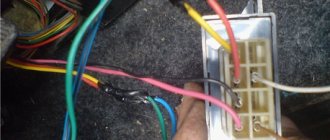
We remove the old turn signal relay by unscrewing the nut securing it to the front panel and disconnecting the three wires from it. (the colors of the wires must correspond to the colors in diagram 2101) In order not to lose the nut, immediately put a new relay in this place and lightly screw the nut on. (don't delay)
I hope that you have already decided where you will install the hazard warning button... If not, then decide quickly, because we are starting to lay the wires and pull them to where the hazard warning button will be. My button is located in the console for the VAZ 2107 receiver in place of the potentiometer, but as an option, I was thinking of installing the button in the radio plug in the dashboard. (to the right of the steering wheel)
Relay contact 2 is connected to the wire removed from contact “L” of the old relay and to contact 7 of the hazard warning button. Relay contact 1 is connected to contact 4 of the hazard warning button. Relay contact 3 is connected to the wire removed from contact “P” of the old relay. We attach the wire from contact 4 to ground (vehicle body). The optimal place is under the relay mounting nut.
By the way, after all of the above has already been done, you can tighten the relay mounting nut. (don’t overdo it, the mount is plastic, it can break)
Button contact 4 should already be connected to relay contact 1. Contact button 2 is connected to the wire removed from the “+” contact of the old relay. Button contact 7 should already be connected to relay contact 2. We connect button contacts 1 and 3 to the steering column turn signal switch; the connection order is not important.
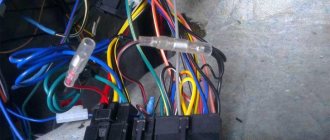
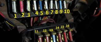
The locations in the block look like this (there are 8 contacts in the block we need):
Contact button 8 is connected to the positive, which does not depend on the position of the key in the ignition switch. You can use the plus from the cigarette lighter. If the plus is taken from the battery or from the generator, then it is advisable to protect this circuit with an 8A fuse.
Materials:
1. Electrical tape (preferably blue, as it is especially durable) 2. Four-pin turn signal relay from VAZ 2106 3. Relay connector 4. Six-pin alarm switch off button 5. Connector for the button 6. Wire for mounting and connecting the above. Tools: 1. Pliers with wire cutters 2. Flat-head screwdrivers 3. Phillips screwdrivers 4. Open-end wrench 10 5. Knife For those who want to save money at the expense of manufacturability: you can use the original relay from the VAZ 2101, but in this case it will work adequately not guaranteed as this relay is very sensitive to load changes. For this reason, the following installation method involves replacing the relay with a more modern one. Let's get started, unscrew the nut securing the turn signal relay and disconnect three multi-colored wires from it. Next, we determine where to install the hazard warning button. Here we give freedom to our imagination, but a lot also depends on what kind of panel is installed in your car. To the second contact of the relay we connect the wire removed from the contact of the old relay, marked with the letter “L”, and connect all this to the seventh contact of the alarm button. We connect the first contact of the emergency light relay to the fourth contact of the button. We connect the third contact of the relay with the wire removed from the “P” contact of the old relay. We attach the wire coming from the fourth contact of the relay to the car body. The optimal solution would be to secure the wire under the fastening nut of our relay.
Scheme of emergency lights (hazard warning lights) for VAZ 2101 cars
→ Get useful materials for VAZ 2101-2110
Thanks for subscribing!
Now tighten the relay mounting nut with moderate force so as not to break the plastic mount. Then we connect the second contact of the button to the positive wire of the old relay. We connect the first and third contacts of the button to the steering column turn signal switches in any order. The eighth contact of the button is connected to a constant “plus” (independent of the position of the key in the ignition switch). It is advisable to protect this circuit with a fuse. The most suitable would be to install a fuse rated 8A. Next, you should wrap the wires with electrical tape and secure them so that they do not dangle, and install all the previously removed casings and panels. Now we have a full-fledged alarm system and can live a new, full life. The entire procedure for installing an alarm system on a VAZ 2101 takes 2-3 hours.
Installation of emergency lights on a VAZ 2101
To install the emergency lights on a VAZ 2101 with our own hands, we need: an emergency light button from the six and a chip for it, a six-pin turn relay, a six-pin chip for the turn relay.
Here is the diagram for turning on the VAZ 2101 turns:
1 – sidelights; 2 – side direction indicators; 3 – battery; 4 – generator; 5 – ignition switch; 6 – fuse block; 7 – relay-interrupter of direction indicators; 8 – indicator lamp for direction indicators; 9 – direction indicator switch; 10 – rear lights
And this is the diagram for turning on the turns and hazard warning lights of the VAZ-2106:
1 – sidelights; 2 – side direction indicators; 3 – battery; 4 – generator; 5 – ignition switch; 6 – main fuse block; 7 – additional fuse block; 8 – relay-breaker for alarm and direction indicators; 9 – control lamp for direction indicators in the speedometer; 10 – alarm switch; 11 – rear lights; 12 – direction indicator switch in a three-lever switch.
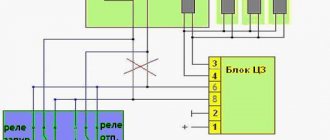
And this is the wiring diagram for the VAZ-2106 turn signal relay (view of the contacts):
We make the connection in the following sequence:
1. Disconnect the old turn relay (barrel) and connect the blue wire to pin 3 of the new relay, this is the control on the panel.
2. Connect a piece of wire to the 4th terminal of the new relay; when attaching the new relay, screw it to ground.
3. Connect the white and black wire (sometimes purple) to the 2nd pin of the relay and to the 7th pin of the hazard warning button (the numbers on the button are written on the back).
4. Add the orange wire (ignition) and connect it to pin No. 2 of the button.
5. Connect pin 1 of the turn signal relay to pin No. 4 of the hazard warning button.
6. We supply constant power to pin 8 of the button, for example from the first fuse.
7. Connect pin 1 of the button to the blue wire in the tube chip.
8. Connect pin 3 of the button to the blue one with a black stripe in the tube chip.
There is another option.
Ready-made wiring for connecting an alarm system is sold on the market:
Installation of emergency lights on a VAZ 2101
: Red - to white with a black stripe (or purple), this is the load. Yellow - to blue (this is a control). Blue - to orange (ignition). Brown with a red stripe is a permanent plus (for example, on the first fuse). White and brown with a white stripe to the tube chip (left and right turns).
We attach the turn relay in place of the old one, not forgetting about the masses. We cut a round hole for the hazard warning button (the hole for the washer pump is ideal, but not on all models). If you want to somehow transform the car, I advise you to install the front windows from a VAZ 2107 with your own hands, it looks just super!
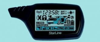
How to use the ignition switch
Any alarm equipped with auto-start is usually equipped with 5 power terminals:
Cord 3 here is the control one; it is connected to the starter terminal. And on the blue wire, that is, on terminal 15/2, the voltage may disappear when the starter is running, or it may remain on it all the time. When setting up, select one option.
VAZ 2101-2107 cars have their own characteristics. The coil of the additional relay shown in the diagram cannot be connected to the ignition cord going to the standard relay. The line is simply not designed for additional load!
Let's see what the ignition switch looks like in reality:
If you really need autostart, the starter cord (red) will have to be cut. Let's list what the correspondence between the lock and alarm cords looks like. The alarm cable will be indicated on the left:
- Green – free;
- Blue – free;
- Red – pink;
- Black-yellow thick – red (tap to starter);
- Black-yellow thin – red (bend to the lock);
- Yellow - blue thick.
In theory, everything turns out simple.
Of course, you can install the autostart system yourself. But it is better to entrust this task to a professional electrician. The three cords leading to the alarm must carry significant current. In new VAZ models the number of these cords will be no less.
Installation and connection of emergency lights on the Kopeyka - VAZ 2101: recommendations + diagram
All modern cars are equipped with hazard warning lights, which cannot be said about older cars. For example, in this article we will talk about the legendary Russian “Kopeyka” - VAZ 2101. Since these cars are not equipped with a warning light, car owners have to install it themselves. What is the wiring diagram for the emergency lights on the VAZ 2101 and how to correctly carry out this task - read on.
System cost
Today, there are a huge number of models and brands of anti-theft systems, differing in the degree of vehicle protection. The cost of an alarm can reach tens of thousands of rubles and vary depending on the manufacturer, sensor sensitivity and additional functions.
You can choose a model from any price category - both a budget option and a luxury one. Most motorcycle owners try to choose expensive systems because they provide the best level of protection and have additional features. Such models are also simple and easy to use.
The most affordable in terms of cost are Chinese systems, but they have their drawbacks: the sensitivity of the sensors is too low at a high signal level. Installing an alarm system on a Stels motorcycle, made in China, will provide an average level of protection, which is quite enough to protect the vehicle from attack.
Purpose and functions of the alarm system
The emergency warning light on the VAZ 2101 is used to notify other road users that the vehicle has made a forced stop due to a malfunction. In accordance with the rules of the road, if a car breaks down, in some cases the driver is obliged not only to turn on the emergency lights, but also to display the appropriate sign. Moreover, it must be placed at a certain distance from the car - this issue is regulated by traffic rules.
Emergency button on a penny
Conclusion
The turn relay is a small but extremely important component of a car's warning light system. It allows the driver to be more predictable for other road users, which, of course, has the best effect on traffic safety and, to some extent, comfort. If the relay fails, the problem cannot be ignored under any circumstances. Fortunately, the relay is not an expensive component of lighting systems, so a car enthusiast can take two devices at once with almost no loss of budget - the second one will be in the trunk, garage or at home in reserve. This is exactly what we advise you to do.
Installation and configuration instructions
Installing emergency lights on a VAZ 2101 is not a particularly difficult task; almost anyone can cope with it. To properly connect the emergency lights to a VAZ 2101 with your own hands, you need to prepare everything you may need to complete the task.
Set of tools and materials
So, what you need to prepare before starting the process:
- Locksmith tools, including wrenches, screwdrivers, pliers, etc.
- Insulating tape.
- Four-contact light signal relay from the “Six”.
- Six-pin button for activation.
- Five meters of installation wire (video by Alex Gordon).
Work execution algorithm
So, let's start the process:
- First you need to remove the center console. To do this, you need to unscrew the bolts that secure the trim to the steering column. You will also need to remove the side trims of the windshield pillars.
- Having done this, you can remove the instrument cluster. Be careful not to damage the device.
- Next, disconnect the wires from the light bulb that illuminates the glove compartment. Then unscrew the bolts that secure the sides of the glove compartment to the control panel, as well as the bolts that secure its lower part. After unscrewing all the screws, the glove compartment itself can be removed.
- Now you need to remove the screws that secure the bottom of the dash to the front cross member. Then the nuts of the upper fastening are unscrewed; it is best to reach them through the technological opening of the glove compartment.
- After completing these steps, you can remove the handles from the stove control panel. To do this, at the junction of the lever with the handle, use a screwdriver to bend the lower part of the upper handle, and at the lower handle, you need to bend the upper part.
- Next, you need to disconnect the connectors with wires from the control panel backlight switches, side lights, and also the stove. Then, using a wrench, you need to unscrew two more bolts that secure the fastenings of the stove control levers. After completing these steps, you will be able to dismantle the control panel.
- Now let's move on to installing and connecting the main elements. First, decide on the location of installation of the system power button. It should be installed on the center console so that the driver can reach it as quickly as possible if necessary. It’s still too early to install the button, but you need to decide on the installation location now, since this will determine how much wire you need. Now remove the old turn signal relay from the car and disconnect the three cables from it - usually they are colored black, gray-white and orange.
- Next, take a new six-wheel relay. The second contact of the relay must be connected to the wire that was removed from contact L on the turn signal relay, as well as to output 7 of the button.
- The first contact of the relay must be connected to the fourth contact on the button itself. The third contact is connected to the cable disconnected from contact P on the turn signal relay. Then you need to connect the cable from the fourth contact to ground, that is, the body of the vehicle - it is best to connect it to the relay fixing nut.
- The next step is to connect the button itself. The fourth contact of the button should be connected to the first contact of the relay used. Its second contact must be connected to the cable that was disconnected from the positive contact of the rotary relay. The seventh contact is connected to the second contact of the relay, and the first and third contacts are connected to the steering column turn signal switch; in this case, the order of connection does not matter.
- Now all you have to do is connect the eighth pin to any positive cable; alternatively, you can wedge it into the electrical circuit from the cigarette lighter. If you decide to connect the plus directly to the battery or generator unit, the circuit will need to be protected with a fuse.
- At this point, the installation procedure can be considered complete. All you have to do is securely fix the wiring to prevent chafing of the cables. Reinstall all previously removed interior trim elements, center console, glove compartment, etc.
Design and principle of operation of an electromagnetic-thermal turn relay
Relays of this type do not have a very complicated design. It is based on an electromagnetic relay of a traditional design - a cylindrical core with a winding of thin copper wire. At the top of the core there are two contact groups, and on the sides there are flexible metal anchors (or, as they are called, anchors). One contact group is designed to close the circuit of the turn signal indicator lamp located on the dashboard. And the second contact group directly closes the circuits of the direction indicator lamps, and it is its design features that ensure the blinking of the turn signals.
The armature of the contact group of the turn signal lamps is pulled away from the contact located on the core using a thin nichrome string, so in the normal position the turn signal circuit is open. The opposite end of the string is fixed on a platform made of insulating material, which serves as the basis for installing the core. The nichrome string is connected through a resistor to the turn signal switch circuit, so current flows through it during operation of the relay.
This entire structure is placed in a cylindrical metal case; the bottom of the case is a platform made of insulating material with a relay. At the bottom of the platform there are contacts with the help of which the breaker relay is connected to the turn signal circuit.
The operation of an electromagnetic-thermal relay is quite simple and boils down to the following. When the turn signal is turned on, a circuit is closed that includes the turn signal lamps, a resistor, a relay winding and a nichrome string. Due to the resistance of the resistor, the voltage supplied to the lamps is low, so their filaments burn at full heat. Nichrome, as is known, has a high resistivity and heats up greatly when current flows - thanks to this heating, the nichrome string increases its length, and the armature pulled by it, under the influence of the attraction of the core, straightens and at some point closes the contact group. As a result, current begins to flow bypassing the resistor and the nichrome string, and the turn signal lamps light up in full force.
However, stopping the heating of the string leads to its cooling and shortening, and the armature is again pulled away from the core, opening the contacts - the turn signal lamps go out, and the cycle repeats again. The heating and cooling of the nichrome string occurs quickly, so the lamps blink at a frequency ranging from 60 to 120 times per minute.
The current position of the contact group of the direction indicator lamps (let's call it the first) is associated with the work of the contact group of the signal lamp (let's call it the second). When the contacts of the first group are open, current flows through the winding, but it is not enough to attract the armature of the second group, so the signal lamp does not light up. When the string is pulled and the first contact group is closed, the current flowing through the winding increases sharply, and it is already sufficient to attract the armature of the second contact group. As a result, simultaneously with the blinking of the direction indicators, the warning light on the dashboard also blinks.
Characteristic clicks during operation of the direction indicators occur due to the impact of the anchors on the contacts when they are closed and opened. Clicking is a characteristic feature of electromagnetic relays, and it comes in very handy in breakers.
The electromagnetic-thermal relay has a simple design, and this is its main advantage. But this type of relay has many more disadvantages: over time, the string is stretched, as a result of which the relay stops functioning normally, during operation the relay heats up, which changes its characteristics, and if one of the turn signal lamps burns out, the blinking frequency of the second lamp decreases significantly, and In some cases, the lamp stops lighting up altogether.
VAZ-2101 diagram
The “penny” circuit diagram guide is intended for self-repair of a car in case of minor electrical equipment problems. Start the repair by checking the fuses and relays (description and designation will follow). The electrical circuits are divided into several blocks (for ease of viewing via a computer or phone), there are files in the form of a single picture with a description of each element - for printing on a printer. This is a small car, an analogue of the Fiat 124. Years of production of the VAZ-2101: from 1984 to 2014.
As in all other Zhiguli models, the electrical wiring of the penny is made according to a single-wire circuit. Power is supplied to all electrical devices through one wire, and the negative wire is the car body.
Basic Concepts
In order to understand wiring, you need to understand a little about the types of current. A constant is one that does not change its direction and magnitude. Variable is one where the voltage and current change their value after some time, or the current flows in the opposite direction. Often direct current, as can be seen in the wiring diagram of the Alpha moped, is needed for light bulbs: headlights, turn signals, foot. There are models where the motorcycle is completely converted to direct current, but these are old models and they are quite rare.
Electrical equipment VAZ 2101
Scheme of a penny in parts:
1 – headlights 2101; 2 – front direction indicators; 3 – side direction indicators; 4 – battery; 5 – battery charge warning lamp relay; 6 – relay for turning on low beam headlights; 7 – relay for turning on the high beam headlights; 8 – generator; 9 – starter; 10 – engine compartment lamp; 11 – spark plugs; 12 – oil pressure warning lamp sensor; 13 – coolant temperature indicator sensor; 14 – sound signals; 15 – ignition distributor; 16 – windshield wiper gear motor; 17 – brake fluid level warning lamp sensor; 18 – ignition coil; 19 – electric motor for windshield washer; 20 – voltage regulator; 21 – heater electric motor; 22 – glove box lighting lamp; 23 – additional resistor of the heater electric motor; 24 – plug socket for a portable lamp; 25 – parking brake warning lamp switch; 26 – brake signal switch; 27 – relay-interrupter of direction indicators; 28 – reverse light switch; 29 – fuse block; 30 – relay-interrupter for the parking brake warning lamp; 31 – windshield wiper relay; 32 — heater motor switch; 33 – cigarette lighter; 34 – lamp switches located in the rear door pillars; 35 – lamp switches located in the front door pillars; 36 – lampshades of VAZ-2101; 37 – ignition switch; 38 – instrument cluster; 39 – coolant temperature indicator; 40 – control lamp for high beam headlights; 41 – indicator lamp for external lighting; 42 – turn signal indicator lamp; 43 – battery charge indicator lamp; 44 – oil pressure warning lamp; 45 – control lamp for parking brake and brake fluid level; 46 – fuel level indicator; 47 – fuel reserve warning lamp; 48 – instrument cluster lighting lamp; 49 – headlight switch; 50 – direction indicator switch; 51 – sound signal switch; 52 – windshield washer switch; 53 – wiper switch; 54 – external lighting switch; 55 – instrument lighting switch; 56 – sensor for level indicator and fuel reserve; 57 – trunk lighting lamp; 58 – rear lights; 59 – license plate light; 60 – reversing lamp
Full size wiring diagram (for printing):
Another version of the VAZ-2101 scheme
Outdoor Lighting
1 – Headlights 2101 2 – engine compartment lamp; 3 – battery; 4 – generator; 5 – reverse light switch; 6 – fuse block; 7 – indicator lamp for external lighting in the instrument cluster; 8 – glove box lighting lamp; 9 – instrument cluster lighting lamp; 10 – plug socket for a portable lamp; 11 – instrument lighting switch; 12 – external lighting switch; 13 – brake light switch; 14 – ignition switch; 15 – lamp switches located in the front door pillars; 16 – lamp switches located in the rear door pillars; 17 – lampshades; 18 – trunk lighting lamp; 19 – rear lights; 20 – license plate light; 21 – reversing lamp
Turning on the headlights 2101
1 – headlights VAZ 2101; 2 – battery; 3 – generator; 4 – fuse block; 5 – headlight switch; 6 – external lighting switch; 7 – ignition switch; 8 – indicator lamp for high beam headlights in the instrument cluster
Direction indicators
1 – sidelights VAZ 2101; 2 – side direction indicators; 3 – battery; 4 – generator; 5 – ignition switch; 6 – fuse block; 7 – relay-interrupter of direction indicators; 8 – indicator lamp for direction indicators; 9 – direction indicator switch; 10 – rear lights
Sound signals 2101
1 – sound signals; 2 – battery; 3 – fuse block; 4 – sound signal switch; 5 – generator VAZ 2101.