Print this article Font size 16
When the generator is turned on, it produces direct current. But to power all consumers in the car and recharge the battery, alternating current with a clearly defined frequency is required.
The diode bridge performs the functions of converting direct current into alternating current. This device is also called a rectifier.
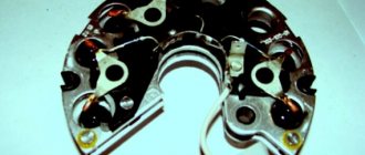
Element appearance
Diode bridges can have different designs. However, cars are mainly equipped with three-phase rectifiers. This is due to the important advantages that they possess. Namely:
- The output produces the most pulsating voltage;
- Three-phase devices are excellent for half bridges and diode bridges;
- Their design allows the additional use of a capacitor - a current filter.
Checking and replacing the diode bridge of the VAZ 2110 generator with your own hands
Once it starts working, the generator begins to produce direct current, but to operate all the devices in the car, as well as to charge the battery, an alternating current is needed (pulsating with a clearly defined frequency).
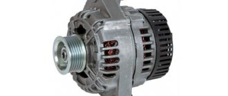
Diode bridge 2110-3701315 “StartVOLT” for VAZ 2110-2172 generators produced by KZATE
It is the conversion of current that the diode bridge of the VAZ 2110 generator, which is also called a rectifier, is engaged in. And although there are many design options, the cars are equipped with three-phase ones, the advantages of which are obvious:
- At the output they create the smallest ripple voltage;
- Three-phase rectifiers are suitable for bridge and half-bridge diodes;
- They make it possible to install an additional capacitor - a current filter.
Features of a car generator
After turning the ignition key, current flows into the field winding. Here it is controlled by a voltage stabilizer, which is powered by the rectifier section.
A car generator produces alternating current, which, after rectification by a diode bridge, becomes constant. Thus, such a unit belongs to the group of DC valve generators.
Its distinctive feature is maintaining voltage within a narrow range of values. A special regulator, which is popularly called “tablet”, “chocolate”, “brushes”, is responsible for the voltage of the generator.
These devices increase the voltage to 13.6 Volts.
Today they are connected according to two main schemes. The older version is reliable, works stably, maintaining voltage at approximately a constant level. The updated scheme has many disadvantages.
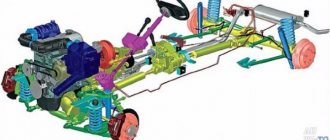
The uniqueness of the automobile unit is that it generates electricity by converting the mechanical energy of the rotating engine crankshaft, which is connected to the generator pulley by a belt. At the same time, the engine speed is not a constant value.
Thus, the main task of this electrical unit is to charge the battery and supply all car consumers with stabilized voltage.
In this case, regardless of engine speed, the voltage should always remain within approximately 14 Volts. Otherwise, it will negatively affect both the battery and the electrical circuit. Overcharging and undercharging will have a detrimental effect on the battery.
Design
In the original (factory) configuration, the diode bridge of the generator on the VAZ 2110 is a monolithic structure. It is quite reliable, inexpensive, compact, and has, one might say, only one drawback: if one of the diodes burns out, its local replacement is impossible; you need to buy a new factory bridge and install it.
In the event that a check shows that the diode bridge is no longer functioning and needs to be replaced, it is quite possible to assemble it from various diodes. If the factory layout provides four or six diodes, then during self-assembly you can install an additional one.
Many car enthusiasts do this. In addition, as a rule, in the case of self-assembly, diodes are installed not in the factory layout, but a little stronger, so that they do not burn out so quickly.
But since it is impossible to qualitatively test such a rectifier, during “home assembly” you can damage the generator, after which it will be necessary to replace not just a cheap part, but the entire assembly.
Causes of breakdowns
As numerous checks show, the main cause of breakdowns is factory. Here, first of all, you need to pay attention to the shell in which the diodes are located. If it is aluminum, it is better not to take such a unit. Much more reliable is steel.
In addition, if the seller does not provide a guarantee, you should be wary. According to reviews on the Internet, the most unreliable diode bridges are made in Belarus.
- Another reason is moisture ingress, which results in oxidation of the space between the diode itself and the housing;
- Contact of oil or other working fluids of the VAZ 2110 on the surface;
- If you reverse the polarity of the battery while lighting or charging, the diode bridge can easily “fly out”;
- You can also suspect that the VAZ 2110’s rectifier is failing if the battery stops charging.
conclusions
Increasing the voltage of the VAZ-2114 generator with your own hands is real and quite simple. At the same time, the cost amounted to 500 rubles. It is worth noting separately that if you do not have the necessary skills or abilities to work with automotive electronics, then you should contact a car service center, where everything will be done quickly and efficiently, and of course, at the expense of the car enthusiast.
Greetings car enthusiasts. Today I’ll tell you how to increase the voltage on a car’s generator in a simple way, if for some reason it does not correspond to the norm of 14.4 volts.
So, to solve this problem, there is a very simple way to increase the voltage of the generator with a diode, which we will simply add to the main circuit of the generator.
2D219 diodes are suitable for this purpose; 2D 213 (diodes naturally have a letter index).
It is the letter index of the diode that will be responsible for the amount of the required voltage drop across this diode.
The diodes used must have a breakdown voltage of about 20 volts and a current of at least 5 amperes, the voltage drop across the diode should be in the range from 0.6 volts to 1.2 volts (here you need to look at how much you need to raise the voltage).
Probably for those who do not understand electricity, nothing is clear at all. I'll try to explain it more simply.
Let's assume that your generator produces 13.3 V - 13.5 V at partial load, and this is unacceptably low for recharging the battery and, in turn, the battery in the near future simply will not be able to provide the necessary energy to start the car.
But if you use a diode to increase the generator voltage by about 1 V-1.1 V, then everything will fall into place.
The voltage at the generator output will increase by reducing the voltage supplied to the power output of the voltage regulator, so the regulator does not seem to receive additional voltage in order to operate within the specified limits. The voltage is extinguished at the diode and thereby the regulator increases the excitation voltage (on the brushes), and the generator, in turn, produces a voltage higher by exactly the amount by which we extinguished the diode. Something like that.
Examination
Using a multimeter it is very easy to check the serviceability. Need to:
- Place the positive probe of the multimeter at the positive diode bus;
- Do the same with the negative probe and the “-” diode output;
- This test, if the diode bridge is working properly, should give readings close to infinity. If this is not the case, there is a malfunction and needs replacement;
- Now we swap the probes (put plus to minus and vice versa);
- Let's look at the readings. If the unit is working properly, the readings should be several hundred ohms;
- To check the additional diode, perform the same steps as described above.
Replacement
When dealing with any component related to electrical equipment, you need to start by de-energizing the VAZ 2110. So, we proceed according to the algorithm:
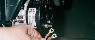
- Disconnecting the battery (remove the “-” terminal);
- Remove the pink wire that turns on the generator. To do this, you need to unscrew the nut from the positive bolt;
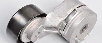
- Loosen the upper and lower nuts, and also unscrew the tension bolt, remove the belt;
- Turn the generator 90° and remove the lower mounting bolt;
- Clean all connections, as well as the rectifier housing itself;
- Clean the inside of the ring very thoroughly;
- Replace the generator diode bridge with a new one;
- Reassemble all parts;
- Check the functionality of the generator.
Source
How to replace a diode in a generator diode bridge
As you know, a car generator is designed to provide power to all electrical equipment in the car when the engine is running. This unit in domestic “tens” consists of many elements that ensure its optimal operation. One such device is a diode bridge. What functions does it perform, what do you need to know about its malfunctions, and how is the diode bridge of the VAZ 2110 generator replaced? You can find answers to these and other questions below.
What methods can be used to increase generator voltage
To independently correct the voltage of the VAZ-2110 generator, you need to have on hand:
- Available device diagram.
- Voltage regulator from a domestic car.
- Voltage regulator from a foreign car.
- Necessary tools that may be required during the work process.
Having prepared everything you need, you should start upgrading the generator yourself, performing the work in stages:
- protection, called a tablet, is removed from the domestic regulator. At the end of the work, the body of the unit should be bare, only the brushes should remain on it;
- Using a generator from a foreign car (it is advisable to take a device with a voltage cycle of at least 15 V), connect its tablet to the bare body of the main component. The soldering method is used to connect the inputs;
- before connecting, you need to make sure that both ends are bent correctly, otherwise they simply cannot be positioned under the main body of the device;
- for additional fixation of the tablet to the body, it is recommended to use a bolt with a nut of the appropriate size;
- when soldering the inputs, be sure to ensure a tight fit to the base of the unit, and the tin layer must completely cover the tablet;
- To prevent the nuts from unwinding on their own when moving, they are sealed with a special compound, for example, sealant.
Having installed the modernized unit in its original place, the car will be equipped with an updated generator with increased power, which can supply a voltage of 15 V.
Description of the diode bridge on the “Ten”
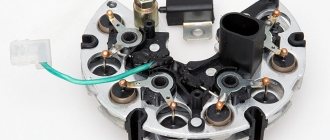
How is the diode modified and installed in the device? For what reasons can a bridge fail? To begin with, we suggest that you familiarize yourself with the description of the part. If you dismantle the generator assembly from the car and remove the cover, you will be able to see the diode bridge (DM), which is located immediately behind it.
Purpose and functions
What functions does the DM perform:
- The primary task of the device is to convert alternating current into direct current.
- The DM also performs the function of blocking current from entering the stator winding. In this case, the device actually performs the one-way valve option.
- In addition, the DM is designed to increase the safety margin of the generator unit. It allows you to protect the mechanism from the effects of adverse factors and contamination on the device, and this, in turn, can negatively affect the functionality of the mechanism as a whole.
Device
As for the device, in the factory configuration the DM for the “tenth” generator is a monolithic structure. This design, as a rule, is quite strong and reliable, is characterized by its small size, as well as a relatively low price. The only drawback characteristic of factory-made DMs is that if one of the diode elements burns out, local replacement of the damage will not be possible. That is, the car owner will have to completely change the factory axle with his own hands.
As for the design features itself, the DM consists of:
- two aluminum plates;
- spacers made of plastic;
- as well as nine diodes, which are connected to each other by soldering into one structure, that is, a bridge.
A few words about its structure
The generator set of this car is a fairly reliable device that can withstand vibration loads and temperature changes in the engine compartment. She is also not afraid of moisture and dirt getting in while driving. Its performance should be stable at any engine speed.
Requirements for the generator:
- The strength of the current generated by the device must be such as to prevent the battery from being discharged, but to be recharged to the required level regardless of the connected consumers;
- Regardless of the engine speed and fluctuations in current consumption, the stability of the on-board voltage must be ensured.
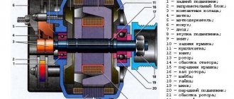
It is an electrical machine that converts rotational motion from the engine crankshaft into constant voltage to recharge the battery. Its body consists of two halves, front and back. The back cover is responsible for attaching a brush assembly with a relay-regulator, a diode bridge, and terminals for connecting consumers of the generated electric current.
The main component of this device is the stator, which generates electrical voltage. It is installed between the halves of the body, front and rear. A rotor with an excitation winding rotates in a housing on bearings. Voltage is supplied to this winding through copper rings on the rotor shaft, and it is supplied to them through a brush assembly mounted on the back cover.
About possible improvements
. Today, lovers of additional consumers of electric current in a car have two ways to increase the battery charging voltage. Let's look at them.
Possible malfunctions: signs and causes
As stated above, the purpose of diode elements is to convert alternating voltage to direct voltage. If one of the diode elements fails, then its malfunction may be indicated by such a sign as a decrease in the voltage level, as well as power in the vehicle electrical network.
For what reasons may problems occur in the operation of the DM:
- Manufacturing defects. As practice shows, many modern DM manufacturers use aluminum shells of fairly low quality in their production. Accordingly, this affects their reliability as a whole. That is why it is recommended to use DM equipped with steel shells, since this directly affects the service life.
- Moisture gets inside the device. Regular exposure to moisture can cause oxidation, in particular, on the surface between the device body and diode elements.
- Engine fluid getting into the unit is one of the most common causes. Exposure to lubricant can lead to disruption of the functionality of the device as a whole, especially if it gets inside the generator unit, directly on the DM.
- Another reason why DMs on “tens” often fail is the polarity of the battery is reversed. If you connect the battery to a charger or accidentally reverse the polarity while “lighting up” the car, this will most likely cause the motor to burn out. Therefore, you should always remember that plus is connected to plus, and minus is connected to minus.
- Regular operation of a vehicle with a weak battery. If the battery does not pull the load and constantly operates under conditions of reduced charge, then the reason may be the inoperability of the DM.
How to increase the voltage on your car's alternator yourself
Greetings car enthusiasts. Today I’ll tell you how to increase the voltage on a car’s generator in a simple way, if for some reason it does not correspond to the norm of 14.4 volts.
So, to solve this problem, there is a very simple way to increase the voltage of the generator with a diode, which we will simply add to the main circuit of the generator.
2D219 diodes are suitable for this purpose; 2D 213 (diodes naturally have a letter index).
It is the letter index of the diode that will be responsible for the amount of the required voltage drop across this diode.
The diodes used must have a breakdown voltage of about 20 volts and a current of at least 5 amperes, the voltage drop across the diode should be in the range from 0.6 volts to 1.2 volts (here you need to look at how much you need to raise the voltage).
Probably for those who do not understand electricity, nothing is clear at all. I'll try to explain it more simply.
Let's assume that your generator produces 13.3 V - 13.5 V at partial load, and this is unacceptably low for recharging the battery and, in turn, the battery in the near future simply will not be able to provide the necessary energy to start the car.
But if you use a diode to increase the generator voltage by about 1 V-1.1 V, then everything will fall into place.
The voltage at the generator output will increase by reducing the voltage supplied to the power output of the voltage regulator, so the regulator does not seem to receive additional voltage in order to operate within the specified limits. The voltage is extinguished at the diode and thereby the regulator increases the excitation voltage (on the brushes), and the generator, in turn, produces a voltage higher by exactly the amount by which we extinguished the diode. Something like that.
The figure shows a standard circuit for connecting a generator to a car's power system; there is no diode to increase the generator voltage.
The power diodes are indicated in green, the diodes supplying the voltage regulator are indicated in blue, the yellow square is the voltage regulator itself, the light in the instrument panel is indicated in red (battery charging), the purple rectangle is the load (it is a variable value).
This circuit already contains a diode, which is installed in the gap between the power output of the voltage regulator and the diodes of the generator feeding it.
Now let's look at how to increase the generator voltage.
The current from the battery runs through the light bulb (which lights up) and then through our diode to increase the voltage of the generator, the voltage regulator is powered, which opens its internal transistor to its full extent, and the current begins to pass through the brushes, and since the brushes are installed on the generator armature, then The rotor winding is accordingly also energized. And in order for the generator to work, you just need to start turning it using the engine.
As you can see from this diagram, the light bulb will go out due to the fact that the same positive voltage will come to it from both sides.
But the diode to increase the voltage of the generator will put on itself a certain amount of volts (depending on which diode you choose), and the regulator will accordingly receive less of this voltage.
This means that the same internal transistor of the voltage regulator will be open a little more (i.e. exactly those volts that we did not give to the voltage regulator).
This looks like cheating the voltage regulator, the on-board network receives the required voltage of 14.4 volts, and the regulator thinks that it is less in the on-board network and therefore adds it. Well, in general terms, I think we’ve figured out how to increase the voltage on a car’s generator using a diode.
The figure shows where and how the diode needs to be tricked. What composition you make depends only on you, whether you want it inside the generator or outside it.
As a recommendation, I can advise placing the diode outside and not covering it with anything, it will cool better (it gets very hot).
And the most important thing is that the picture shows the location of the break; in fact, it is not necessary to cut, there is a terminal there; you just need to take it out and make another one (in general, you’ll figure it out) then insert the diode between the terminals.
I also advise you to look at the interesting article “How an electronic voltage regulator of a car works”, from which you will learn a lot of interesting things about the voltage regulator of a car generator, and in the article “How to check the operation of a generator in a car yourself” you will read about how to properly check the generator without removing it from the car.
That’s all, I consider the topic of how to increase the voltage on a car’s generator to be considered.
Sincerely, blog author: Doctor Shmi
Diagnostics
The diagnostic procedure must be carried out on a dismantled generator device, so the unit must first be removed. When the mechanism is dismantled, the plastic cover is removed from it, as mentioned above, the DM is located immediately behind it (the author of the video about self-diagnosis with a multimeter is Ramil Abdullin).
For diagnostics you will need a tester - a multimeter - the test is carried out as follows:
- First, the multimeter should be activated in ohmmeter mode. Having done this, the positive probe of the tester must be connected to the diode bus.
- In the same way, connect the negative probe of the tester to the corresponding contact on the diode bridge.
- Next, you need to monitor the tester readings. If the diode bridge is in working condition, then the tester display will show values close to infinity. If there are no such values, then most likely the DM is inoperative and should be replaced. But the diagnosis does not end there.
- Next, you will need to swap the location of the probes, that is, the negative contact is connected to the positive one and vice versa. Having done this, again look at the multimeter reading on the display. If there are no failures in the operation of the DM and the device as a whole is functioning normally, then a value of several hundred Ohms should appear on the tester screen.
- If the DM is equipped with an additional diode, then you can check it too. In this case, the diagnostic procedure is performed in a similar way; you just need to repeat all the steps.
Photo gallery “Self performance test”
Additional testing of generator components faults
The stable operation of this device can be affected not only by the DM and the relay regulator, but also by the electric rotor and stator windings, brushes and capacitor. If the first measurements do not reveal any malfunctions in the operation of the main generator components, then proceed to additional testing of the generator components.
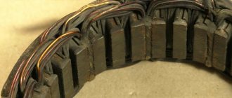
Generator winding testing
This type of measurement is carried out on a dismantled and disassembled generator. You will need to separately check the serviceability of the rotor and stator windings. The meter is set to ohmmeter mode at a value of 200 Ohm.
The main stages of monitoring the electric rotor and stator windings:
- Measure the resistance value on the rotor windings. For this purpose, probes are connected to the outputs of the windings. The normal value is above 5 ohms, if less than 1.9 ohms, there is a turn short on the rotor. Most often, the electrical circuit breaks in the connection areas between the rotor winding and the ring. It is possible to determine the malfunction by moving the wire in the soldering area with a probe. Alternatively, integrity may be compromised here.
- Carefully inspect all connections. It is possible that dark and damaged wire insulation will be detected, which is a consequence of a break and short circuit.
- We call electrical circuits to determine the short circuit on the housing. To do this, the first probe is brought to the rotor shaft, and the second to any ring. If the winding is working properly, the ohmmeter reading will go off scale. If the resistance is low, this winding must be rewound. In this case, perfect balancing must be maintained.
- Before checking the stator, a visual inspection is performed, paying attention to all kinds of external damage to both the housing and the insulator, as well as the places where the wires from the short circuit are burned.
- If a defect is detected, the stator is sent for rewinding.
- If no external abnormalities are found on the stator, examine it with a multimeter.
- The stator must be disconnected from the generator and removed.
- The multimeter is set to resistance control mode. Initially, the probes are installed on the 1st pair of terminals. Then they test a pair of windings “1–3”, and then “3–2”. If the analog multimeter needle goes off the scale, the windings will need to be rewinded.
- To check the generator for the absence of a short circuit between the turns and on the housing. The first probe is connected to the terminal, and the second to the body. If the windings are short-circuited, the multimeter on the scale will show a lower resistance value than on the working ones.
How to check the brushes of a VAZ-2110 generator with a multimeter
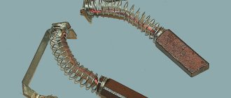
The brush apparatus is removed from the generator and an external inspection is carried out. They wear out during operation due to the fact that they are constantly in contact with the commutator plates, as a result of which wear occurs on both parts of the brushes and the commutator. At a time when wear becomes critically dangerous and the action of the spring becomes insufficient to ensure good contact, the process of excitation of the rotor winding deteriorates. Ultimately, wear of the brushes leads to a drop in charging voltage.
Important! The drop in charging voltage occurs gradually, almost imperceptibly for the car owner, and therefore it can appear at the most inopportune time. The process accelerates in severe frosts, a large number of cold starts, and frequent trips over short distances. This will happen until one day the EMF from the battery is insufficient to start the engine and the car will not start. Such difficulties are especially inherent in diesel cars, since the starter of these engine modifications requires even more current.
Upon external inspection of the brushes, they should be evenly worn, while their length should be equal, and the wear from the generator rotor rings should be symmetrical about the longitudinal axis. The residual size of the brushes should be more than 5 mm, with a norm of 8 to 10 mm. If such characteristics are absent, the brushes are changed in any case, even if the generator failure has other sources.
If the length of the brushes is of an acceptable size, then they need to be checked with a multimeter in resistance control mode. The probes are connected according to the diagram indicated below.
Normal brush resistance should be in the range of 0.5–1 Ohm; brushes with higher values are rejected.
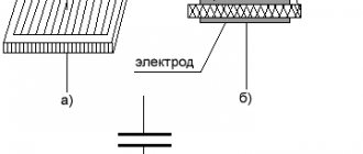
How to check the capacitor of a VAZ-2110 generator with a multimeter
A damaged capacitor also leads to malfunctions. It can be checked with a multimeter on a scale of 1–10 MΩ. The multimeter test leads are connected in one direction to the terminals of the capacitor. Before connecting, the meter shows infinity. When connected, the resistance drops, and then rises again to infinity. In this mode, the capacitor is technically operational.
Important! When reassembling the capacitor and brush holder on the generator, they are installed in the reverse order of dismantling. For those car enthusiasts who are doing this for the first time, it is better to take photos and videos of the process of disassembling the generator. When assembling the capacitor, it must be installed exactly along the mounting protrusion on the cover, otherwise the brush holder will not be installed in place.
The diode bridge is a reliable device that is necessary for the smooth operation of the generator. However, it is not protected from moisture, poor machine maintenance and poor contacts, which lead to premature failure. To make sure that it is faulty, experts recommend checking the VAZ-2110 generator with a multimeter. To do this, you will need to remove it from the generator, which will take no more than 10 minutes. The test is carried out with a multimeter. A working DM should conduct current exclusively in one direction. If this is not the case or the multimeter does not show cross-country ability at all, then such a bridge should be replaced with one of the same type for the VAZ-2110.
DIY replacement instructions
In the event of a breakdown, the repair of the DM consists of its replacement, which is done as follows:
- First you need to turn off the ignition, open the hood and turn off the power to the on-board network; to do this, disconnect the battery.
- Once the battery terminal is reset, you will need to disconnect the pink cable responsible for activating the generator assembly. The wire itself is fixed with a bolt and nut; the nut itself will need to be unscrewed.
- Now you need to slightly loosen the tension on the top as well as the bottom nuts. Unscrew the tension screws and remove the strap. Inspect it - if the belt shows signs of damage - cracks, delamination - then it is better to change it immediately. If the strap is intact, set it aside.
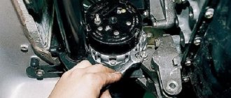
- After completing these steps, you need to rotate the generator mechanism 90 degrees, this is done so that you can access the lower mounting screw. Unscrew it.
- Next, carefully inspect the body of the dismantled unit. If necessary, clean - there should be no dirt, especially on the connections. Dirt getting inside the generator housing can also lead to its incorrect operation and even failure. Bend the fasteners and remove the cover.
- Next, you need to clean the inside of the rings as carefully, but most effectively as possible.
- After this, all you have to do is dismantle the failed DM and replace it with a working part. When the installation is completed, the structure is assembled in the reverse order. Do not forget to tighten the strap, just make sure that it is not too tight, this is important. Having done this, you will need to start the engine of your car and diagnose the operation of the new DM.
We increase the voltage - all options for solving the problem
Voltage in the on-board network after modification
So, many motorists may decide that the way out of this situation is to install a high-power generator, but at the same time they will have to replace the battery with a more capacitive one. This is done in order not to “kill” the battery that is installed on the car, since a voltage overload will lead to the destruction of the internal cells. This option is not suitable because it is too expensive.
Video “How to avoid mistakes when replacing the DM in a VAZ 2110”
More clear instructions for replacing the diode bridge in the “Ten” with a description of the main points and nuances are given in the video below (the author of the video is Semyon Pedan).
Let's start with the fact that a diode bridge is an electrical circuit, a chain of diodes designed to convert alternating current into direct current. A faulty diode bridge is one of the main causes of generator malfunction, and is also a powerful consumer that can drain the battery to zero overnight.
A faulty diode bridge can both discharge and recharge the battery, which can result in major electrical problems. The principle of diodes, in addition to converting current from alternating to direct, is the unipolarity of current transmission from the generator to the battery. In other words, a working diode transmits current only in one direction (generator - battery), a faulty diode transmits current in both directions (battery - generator) or does not transmit anything at all. Diodes burn out due to poor contacts or moisture.
Before you start blaming the diode bridge for all your problems, be sure to check the generator brushes and voltage regulator.
To start checking the diode bridge, you need to remove it, fortunately the process is simple. You can also do without removing the rectifier block (diode bridge), but this is very, very inconvenient.
One way to check the diode bridge is to check the on-board system for current leakage (How to check for current leakage?)! If the current consumption in a stopped engine with electrical appliances turned off is 1A per hour or higher, then most likely the problem lies in the diode bridge. The bridge can only be checked more thoroughly when removed.
Unsustainable breakdown - hurry up with repairs!
It would seem that there is something wrong here - there is not enough tension. The car runs on gasoline, not electricity. However, a lack of current power leads to an increase in fuel consumption, a decrease in engine power, and some electrical appliances stop working altogether and will require replacement in the future. This is especially noticeable in the dark, when many power supply devices are used.
You can deal with this problem easily and quickly by charging it properly. However, sometimes this doesn't help. Look under the hood - the battery terminals may be loose or oxidized. If in a parking lot the current still maintains a constant voltage, then during driving, due to vibration, the terminals may move away, opening the circuit. To fix the problem, you need to thoroughly lubricate the fasteners and tighten the bolts; sometimes only replacing the old terminals with new ones will help.
How to remove the generator diode bridge (rectifier unit)?
- We remove the negative terminal of the battery and disconnect/unscrew the wires going to the plastic casing of the generator.
- Disconnect the wire block “D”.
- Remove the protective rubber cap from the tips of the “+” terminal wires. We unscrew the nut securing these wires and remove them from the generator block.
- Next, remove the black plastic casing of the generator itself. To do this, you need to disconnect the three spring clips located around the perimeter of the block.
- We find the voltage regulator, and use a Phillips screwdriver to unscrew its fastenings.
- We take out the voltage regulator assembly with brushes.
- Take the key to “8” and unscrew the 3 bolts securing the bridge.
- We bend the leads to the stator winding to the side and use a Phillips screwdriver to unscrew the capacitor mount.
We take out the diode bridge! We unscrew the 2 nuts of the contact bolt with a “10” key. We remove the bushing from the contact bolt and remove the bolt itself from the diode bridge. READY! You can start replacing and checking the rectifier unit (diode bridge)!
Modification of the relay regulator
For any modification of the generator set, you need to have at least a little knowledge in the field of electronics. To modify the “relay” for an increased battery charging voltage, you need to purchase the same relay from a foreign car with an output voltage of 14.5 volts, it is indicated on the top cover. The further order will be as follows:
- You need to disconnect the original “pill” from the domestic relay. You need to use a heated soldering iron and tweezers;
- The same procedure is carried out with imported “things”;
- After this, an imported relay must be installed on the domestic brush assembly. Here you will have to work hard, since the pins do not match and they need to be bent and soldered correctly;
- After this, it is securely fastened with screws to the body, having previously been treated with a special heat-shrink paste.
- That's it, you can install the relay regulator on the generator and test it in action, it should produce a voltage equal to 14.5 volts.