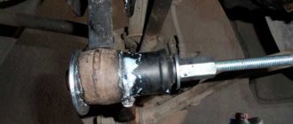
Generator VAZ 2110 converts the mechanical energy of crankshaft rotation into electrical energy, which is used to charge the battery and operate the “tens” electrical networks. Torque is transmitted through the generator drive belt, which connects the engine crankshaft pulley and the generator pulley itself.
The alternator belt is the most important element in the engine-generator connection. If the belt breaks, replacing it is not particularly difficult. Just loosen a couple of nuts. The main difficulty is to ensure correct belt tension.
VAZ 2110 generator belt, tension check
Checking the tension of the VAZ 2110 generator belt must be carried out periodically. If the tension is weak, the alternator belt may simply slip, especially during wet weather. As a result, poor belt tension can lead to insufficient battery charging. But you should not overtighten the alternator belt; this will lead to rapid wear of the belt itself or its unexpected break. In addition, when the belt is overtightened, the generator bearings are subject to additional stress and wear out quickly. Below is a schematic drawing that will help you understand how to properly tension the VAZ 2110 alternator belt.
- 1 – upper bracket of the generator
- 2 – nut
- 3 – generator adjusting bolt
- 4 – generator
- 5 – bolt for hinge mounting of the generator to the bottom bracket
- 6 – generator belt
- 7 – drive pulley on the crankshaft
To ensure normal deflection of the VAZ-2110 generator belt, which is indicated as “A” in the schematic diagram, it is necessary to loosen the generator nut “2” and the bolt nut “5”. Then, by rotating the adjusting bolt “3”, you can move the generator closer/further from the engine, thereby loosening/tensioning the generator belt. The normal deflection of belt “A” should be from 6 to 10 mm, subject to pressure on the belt with a force of 98 N or 10 kgf.
Design of the VAZ 2110 generator
A working generator should deliver from 13 to 14.5 volts to the battery terminals. If this indicator is less when the engine is running and warm, then the generator is faulty. There should be no sudden jumps when consumers are turned on. If the charge is more than 15 volts, this is just as bad; overcharging will quickly damage the battery. When overcharging, water boils away from the electrolyte and the plates crumble. The main reason for the increased charge is the failure of the voltage regulator. Below is a schematic and very detailed image of the VAZ 2110 generator
- 1 – generator pulley
- 2 – washer
- 3 – front cover
- 4 – spacer ring
- 5 – generator rotor
- 6 – generator stator
- 7 – back cover
- 8 – casing
- 9 – rectifier unit with capacitor
- 10 – brush holder with voltage regulator
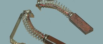
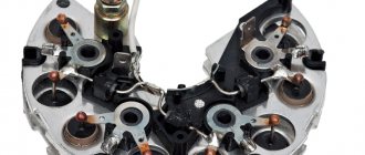
Very often the voltage regulator fails; replacing it is not difficult, since it is not necessary to completely disassemble the VAZ 2110 generator. But due to the fact that the voltage regulator and current-collecting brushes are a single and non-separable part, the replacement is carried out together with the generator brushes.
Often, owners of “ten” are faced with replacing additional diodes that are located on the rectifier block, in the figure above, numbered “9”. To replace generator diodes, you must have epoxy resin and a soldering iron. Using a soldering iron, you need to carefully unsolder the damaged one and solder a new diode. And the resin is necessary for reliable gluing of the diode body. In this case, the old resin must be cleaned off.
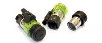
What to choose?
The choice of motorists is not limited to Katek generators. Therefore, if the old device fails, you should think about who will take its place.
There are several main options.
- Katek. A standard, fairly reliable and very efficient generator. AvtoVAZ’s choice in its favor is due precisely to this. Plus it is a domestic manufacturer.
- Chinese products. The attitude of motorists towards Chinese generators is quite skeptical. There are explanations for this. Compared to them, Katek is simply an ideal solution. Although in fairness, we note that you can find some pretty good Chinese-assembled options. But this is the exception rather than the rule.
- Imported analogues. Here, first of all, you should pay attention to Bosch companies. Denso and Delphi. High build quality, impressive service life, efficient operation. They cost more than their Russian counterparts in the form of Katek, but for such a thing it makes sense to spend a little more.
Generator bearing VAZ 2110
Another problem with the VAZ 2110 generator is the rotor bearing. More precisely, two rotor bearings, one at each end of the generator rotor shaft. The front bearing is rolled into the front cover of the generator; the entire assembly is not dismountable, so the bearing must be replaced with the entire cover assembled. The situation with the rear bearing is as follows; it is simply pressed onto the shaft. To remove it you will need a special bearing puller. It is advisable to use a vice to install a new bearing. Because the rotor shaft on which you will press the new bearing must be stationary.
Open circuit (short circuit) in the windings
In a VAZ-2110, the generator may also fail due to a break (short circuit) in the rotor or stator windings. Such a malfunction does not bode well, since it is almost impossible to eliminate it on your own. Here you will need to either rewind the windings or replace the faulty element (rotor or stator).
Before checking the generator on the VAZ-2110, it will need to be removed from the car and disassembled. Let's start with the stator. We take the tester, turn it on in ohmmeter mode and measure the resistance between each winding terminal and the housing. For a working stator it should tend to infinity. If the device shows less than 50 kOhm, there is a short circuit in the winding.
Let's move on to the rotor. Here it is necessary to measure the resistance between the slip rings. It should be within a few ohms. If the resistance is close to zero, the winding turns are closed. If the device produces too high readings, a break may occur.
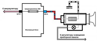
Electrical circuit of the VAZ 2110 generator
The electrical circuit of the VAZ 2110 generator is shown in the detailed figure below.
Basic elements of an electrical circuit.
- 1 – battery
- 2 – generator
- 3 – mounting block
- 4 – ignition switch
- 5 – battery charge indicator lamp, located in the instrument cluster
The “ten” generator is an alternating current unit, three-phase, with a built-in rectifier unit and an electronic voltage regulator. Over the years, generators of both domestic and foreign production were installed on the VAZ-2110, 2111 and 2112 family. Therefore, they may differ structurally.
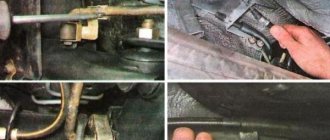
Dismantling and repair
After you have succeeded in removing the device, you need to perform an inspection and find defective parts. It is better to carry out diagnostics at a service station in order to be sure which part needs to be removed and a new one installed. The work must be carried out in a garage with an inspection hole. Disassembly is performed as follows:
- The negative terminal must be disconnected from the battery;
- The next step is to remove the power plant mudguard. After this, access to the generator excitation wires will appear - they must be removed;
After performing troubleshooting, you can understand whether the VAZ 2110 generator needs to be replaced or not. In some cases, it will be enough to replace a few worn parts. When disassembling, you should have a diagram at hand. If you have no experience working with electrical appliances, it is better to contact a service center.
Add a comment Cancel reply
You must be logged in to post a comment.
1 — casing 2 — “B+” terminal for connecting consumers 3 — interference suppression capacitor 2.2 μF 4 — common terminal of additional diodes (connected to the “D+” terminal of the voltage regulator) 5 — holder of positive diodes of the rectifier unit 6 —- holder of negative diodes of the rectifier unit 7—- positive diode 8—- negative diode 9 —— voltage regulator 10 —— back cover 11 —— coupling screw 12 —— front cover 13 —— stator winding 14 —— spacer ring 15 —- front rotor shaft bearing 16 — pulley
17 - nut 18 - rotor shaft 19 - cone washer 20 - washer 21 - beak-shaped rotor pole pieces 22 - stator core 23 - bushing 24 - rotor winding 25 - rear rotor bearing 26 - bearing bushing 27 — slip rings 28 — brush holder 29 — stator winding terminals 30 — additional diode 31 — terminal “D” (common terminal of additional diodes)
The generator is a synchronous AC electrical machine with electromagnetic excitation and a built-in rectifier using silicon diodes. The generator rotor is driven into rotation from the engine crankshaft pulley (damper) by a poly-V belt.
Technical characteristics of generator 94.3701
Maximum output current (at 13 V and 6000 rpm), A
Voltage, V
Engine-generator gear ratio
Direction of rotation (drive side)
The stator and generator covers are secured with four screws. The rotor shaft rotates in bearings installed in the covers. The lubricant placed in the bearings at the factory is designed to last the entire service life of the generator. The rear bearing is pressed onto the rotor shaft and is pressed by the rear cover through a plastic sleeve. The front bearing is pressed and rolled into the front cover and can only be replaced together with it. Its inner race, together with the spacer ring and washer, is clamped by a nut between the pulley and the step on the rotor shaft. The back of the generator is closed with a plastic casing with latches.
Generator device
The design of a car generator implies the presence of its own rectifier and control circuit. The generating part of the generator, using a stationary winding (stator), generates three-phase alternating current, which is then rectified by a series of six large diodes and the direct current charges the battery. Alternating current is induced by the rotating magnetic field of the winding (around the field winding or rotor). Next, the current is supplied to the electronic circuit through the brushes and slip rings.
Generator structure: 1.Nut. 2. Washer. 3.Pulley 4.Front cover. 5. Distance ring. 6.Rotor. 7.Stator. 8.Back cover. 9.Casing. 10. Gasket. 11.Protective sleeve. 12. Rectifier unit with capacitor. 13.Latch holder with voltage regulator.
The generator is located at the front of the car engine and is started using the crankshaft. The connection diagram and operating principle of a car generator are the same for any car. There are, of course, some differences, but they are usually associated with the quality of the manufactured product, the power and the layout of the components in the motor. All modern cars are equipped with alternating current generator sets, which include not only the generator itself, but also a voltage regulator. The regulator equally distributes the current in the excitation winding, and it is due to this that the power of the generator set itself fluctuates at a time when the voltage at the power output terminals remains unchanged.
The principle of operation of a car generator
Connection diagram for the VAZ 2110-2115 generator
The alternator connection diagram includes the following components:
- Battery.
- Generator.
- Fuse block.
- Ignition.
- Dashboard.
- Rectifier block and additional diodes.
The principle of operation is quite simple: when the ignition is turned on plus through the lock, the ignition goes through the fuse box, light bulb, diode bridge and goes through a resistor to minus. When the light on the dashboard lights up, then the plus goes to the generator (to the excitation winding), then during the process of starting the engine, the pulley begins to rotate, the armature also rotates, due to electromagnetic induction, electromotive force is generated and alternating current appears.
Next, the diode passes plus into the rectifier block through a sine wave into the left arm, and minus into the right arm. Additional diodes on the light bulb cut off the negatives and only positives are obtained, then it goes to the dashboard assembly, and the diode that is there allows only the negative to pass through, as a result the light goes out and the positive then goes through the resistor and goes to the negative.
The principle of operation of a car DC generator can be explained as follows: a small direct current begins to flow through the excitation winding, which is regulated by the control unit and is maintained by it at a level of slightly more than 14 V. Most generators in a car are capable of generating at least 45 amperes. The generator operates at 3000 rpm and above - if you look at the ratio of the size of the fan belts for the pulleys, it will be two or three to one in relation to the engine frequency.
To avoid this, the plates and other parts of the generator rectifier are partially or completely covered with an insulating layer. The heat sinks are combined into a monolithic design of the rectifier unit mainly by mounting plates made of insulating material, reinforced with connecting bars.
How to make modifications?
A VAZ 2110 car can have many consumers installed. For example, owners of 2110 often install air conditioning from Priora in the cabin. And if you start all the devices, the voltage can drop to 11.2 volts. The modification allows you to keep the voltage within normal limits, while the generator will provide power to all devices. The modification involves installing a diode. You can take this element from another diode bridge. As an alternative, a diode from KD202V is suitable. To work you will need a standard circuit.
The modification is carried out in circuit D, where a new diode is installed (an option with a current of at least 5A, a voltage drop of 0.6-0.7V and a breakdown of 20V is suitable). As the experience of VAZ 2110 owners shows, the 2D219B diode would be an excellent option. To work you will need 50 cm of 2x0.75 mm wire. Its ends must be sawn to fit the female and male terminals. Now you can put the wire in heat shrink. Armed with a soldering iron, you need to solder the diode on the other side. Next, the “mother” is connected to the anode, and the “father” is connected to the cathode.
The diode must be insulated - a container from photographic film is perfect for this. The next step is to remove the negative terminal of the battery, then unscrew the “plus” from the generator and the “D” wire. After this, there will be open access to the generator cover. Having reached the regulator, you need to run the wires and connect the “male” to the standard wire, and the female to the LV. The modification is completed, assembly is carried out in the reverse order.
Generators that can be installed to replace 9402
9402.3701 ATE – 1 (China LKD)
0124 325 089 BOSCH 90 A
ELD-A-2110-14V-135A with obg. coupling
3747.3771-93 Electrom. Cheboksary.
2110 START – VOLT Ukraine 135A
Operating principle of the generator
Cars use a three-phase synchronous generator. The operating principle of the generator is based on the law of electromagnetic induction. “Electromotive force in a winding occurs when the magnetic field changes.”
The emf of the generator arises in the winding. The rotor serves to create a changing magnetic field. To magnetize the rotor, an excitation winding is built into it. Current is supplied to it through brushes.
The stator winding is three-phase, connected in a star. There is an alternating voltage at the output of the winding, but a constant voltage is required in the car network and for charging the battery, so the output of the winding is connected to a diode bridge (rectifier).
Diode bridge for generator 9402.3701 BPVO 76-105/11, (Electromodule), BVO 3 -105- 01 (Orbit)
Diode bridge for generator 5102.3771 MP 13.80.3.2 (Orbit)
Generator connection diagram for VAZ 2107
The VAZ 2107 charging scheme depends on what type of generator is used. To recharge the battery on cars such as VAZ-2107, VAZ-2104, VAZ-2105, which have a carburetor engine, you will need a G-222 type generator or its equivalent with a maximum output current of 55A. In turn, VAZ-2107 cars with an injection engine use a generator 5142.3771 or its prototype, which is called a high-energy generator, with a maximum output current of 80-90A. It is also possible to install more powerful generators with an output current of up to 100A. Absolutely all types of alternating current generators have built-in rectifier units and voltage regulators; they are usually made in the same housing with brushes or are removable and mounted on the housing itself.
The VAZ 2107 charging circuit has minor differences depending on the year of manufacture of the car. The most important difference is the presence or absence of a charge indicator lamp, which is located on the instrument panel, as well as the method of connecting it and the presence or absence of a voltmeter. Such circuits are mainly used on carburetor cars, while on cars with injection engines the circuit does not change, it is identical to those cars that were manufactured previously.
Generator set designations:
- “Plus” of the power rectifier: “+”, V, 30, V+, WAT.
- “Ground”: “-”, D-, 31, B-, M, E, GRD.
- Excitation winding output: Ш, 67, DF, F, EXC, E, FLD.
- Output for connection to the serviceability lamp: D, D+, 61, L, WL, IND.
- Phase output:
,W,R,STA.
- Output of the stator winding zero point: 0, MP.
- Output of the voltage regulator for connecting it to the on-board network, usually to the “+” of the battery: B, 15, S.
- Voltage regulator output for powering it from the ignition switch: IG.
- Voltage regulator output for connecting it to the on-board computer: FR, F.
Generator circuit VAZ-2107 type 37.3701
- Accumulator battery.
- Generator.
- Voltage regulator.
- Mounting block.
- Ignition switch.
- Voltmeter.
- Battery charge indicator lamp.
When the ignition is turned on, the plus from the lock goes to fuse No. 10, and then goes to the battery charge indicator lamp relay, then goes to the contact and to the coil output. The second terminal of the coil interacts with the central terminal of the starter, where all three windings are connected. If the relay contacts close, then the control lamp lights up. When the engine starts, the generator generates current and an alternating voltage of 7V appears on the windings. Current passes through the relay coil and the armature begins to attract, and the contacts open. Generator No. 15 passes current through fuse No. 9. Similarly, the excitation winding receives power through the brush voltage generator.
Technical specifications
If the old generator fails, many motorists wonder which generator they should now replace the old one with.
There is no need to invent anything here. The most correct solution is to install the same generator as before, or a more powerful one.
Today, the VAZ 2110 provides for the use of three types of power supply devices:
- Katek 5102.3771. The generator produces 80 Ampere power and its voltage is approximately 14V.
- Katek 94.3701. This is a device with the same parameters. They are not seriously different.
- Catek 120 amp. A generator that is more adapted to modern realities, when in addition to standard electrical equipment, motorists install many additional devices.
If you have a powerful audio system in your car, you use an electric pump powered by the car, as well as a number of other additional consumers, it is recommended to install a 120-amp unit instead of a standard 80-amp generator.
If we take into account the size of the devices, then we can distinguish between ordinary and compact ones. They have a certain difference in design. To be specific, the differences are in the following components:
- Brackets;
- Anchor;
- Excitation wire;
- Drive pulley;
- Number of mounting bolts.
But in reality this does not play a special role. After all, the structure of all generators used for the VAZ 2110 is the same. Therefore, let's look at the circuit and structure of this unit.
He's an anchor. It is a rotating element of the generator, which creates a magnetic field due to the excitation winding located on the shaft. The field wire receives power from the slip rings. They are mounted on the same shaft. There was also room for a drive pulley, field winding wire, bearing assembly and fan impeller. There may be 1-2 last ones
This is a stationary three-phase element that includes three windings. They provide the creation of alternating current. The windings are connected to each other using a triangle or star
A lightweight non-magnetic aluminum alloy is most often used to make the generator housing. The body looks like a pair of covers connected by a bolt. The front cover is located near the drive pulley, and the rear cover is located on the side of the slip rings. Each connecting bolt must be tightened. To disassemble the housing, simply unscrew the mounting bolts.
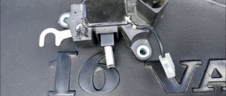
The upper mounting bracket for the generator uses two bolts, while the lower bracket is predominantly mounted on one bolt. In some cases there are two. It is not recommended to modify the brackets, since the factory one performs important functions. The purpose of the brackets is to hold the generator. It is recommended to monitor the condition of the brackets as they are subject to wear and breakage
Charging diagram for VAZ with injection engines
This scheme is identical to the schemes on other VAZ models. It differs from the previous ones in the method of exciting and monitoring the serviceability of the generator. It can be carried out using a special control lamp and a voltmeter on the instrument panel. Also, through the charge lamp, the generator is initially excited at the moment it starts working. During operation, the generator operates “anonymously,” that is, excitation comes directly from pin 30. When the ignition is turned on, power through fuse No. 10 goes to the charging lamp in the instrument panel. Then it goes through the mounting block to pin 61. Three additional diodes provide power to the voltage regulator, which in turn transmits it to the excitation winding of the generator. In this case, the indicator lamp will light up. It is at that moment when the generator operates on the plates of the rectifier bridge that the voltage will be much higher than that of the battery. In this case, the control lamp will not light up, because the voltage on its side on the additional diodes will be lower than on the side of the stator winding and the diodes will close. If the control lamp lights up while the generator is running, this may mean that additional diodes are broken.
Checking generator operation
You can check the functionality of the generator in several ways using certain methods, for example: you can check the output current of the generator, the voltage drop on the wire that connects the current output of the generator to the battery, or check the regulated voltage.
To check, you will need a multimeter, a car battery and a lamp with soldered wires, wires for connecting between the generator and the battery, and you can also take a drill with a suitable head, since you may have to twist the rotor by the nut on the pulley.