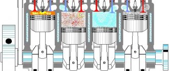
For stable operation of the engine, many different parameters are necessary: from fuel quality to valve permeability. However, the error-free operation of the exhaust system can be called one of the main guarantees of normal engine operation.
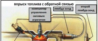
In the exhaust gas system, a catalyst plays an important role, which is designed to purify exhaust substances before they are released into the atmosphere. At the junction between the catalyst and the exhaust manifold there is a special device - an oxygen sensor (otherwise called a lambda probe). And after the catalyst (already at the outlet), a second oxygen sensor is installed, which checks the quality of gas purification and compares the toxicity level with the readings of the first device.
The occurrence of error p0134 on the dashboard can be regarded as a failure of the lambda probe or as a breakdown in the car’s exhaust cleaning system. Accordingly, the uninterrupted operation of the power unit may be disrupted, which can lead to serious financial investments for the owner.
Design
Regardless of the name, lambda probe or oxygen sensor, its essence does not change.
The basis of the device is a ceramic solid electrolyte, the material for which is zirconium dioxide. It is additionally coated with yttrium oxide. But that's not all. There is a coating on top of the ceramic element. It is made from conductive platinum electrodes.
The operating principle is similar to galvanic cells. When the DC is installed on the engine exhaust manifold, due to the influence of the exhaust gas flow, it heats up to approximately 300-400 degrees Celsius.
When heated, the zirconium electrolyte acquires the necessary conductivity, thereby ensuring optimal performance of the sensor.
It is important to install a lambda probe. The DC is positioned so that one electrode receives outside air, and the second breathes a mixture of exhaust gases. When the amount of oxygen changes on one of the electrodes, a potential difference occurs. It is transmitted to the electronic engine control unit via a signal. This allows the ECU to adjust the fuel supply through the fuel injection system.
Indicators
Lambda indicators may vary, but the car requires certain, optimal parameters.
Index
Peculiarity
Lambda equals one
Theoretically, this is the optimal air ratio, at which the actual amount is equal to the required
Lambda is greater than one
Indicates that the air-fuel mixture is lean and therefore the engine is not operating optimally.
Lambda is less than one
Under such circumstances, the mixture turns out to be rich and there is an excess of fuel. Because of this, there is a lack of oxygen necessary to burn such an amount of gasoline
If we talk directly about ideal conditions for the VAZ 2114 and its engines, then the lambda should have a ratio of 14.7 to 1. In other words, the mixture needs to be lean. This is due to the need for a sufficient amount of oxygen on the catalyst to burn CH and CO.
For domestic cars, a modern DC is used, which functions as a threshold element.
How does he work
We have already noted that the DC begins to work only after heating to a certain temperature - 350 degrees Celsius. Because of this, the first variations of the probe were installed in close proximity to the exhaust manifold.
Over time, the sensor was improved, a heating element was built in, which made it possible to quickly bring it to operating parameters. Because of this, the location of the probe in the exhaust system has lost its significance.
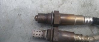
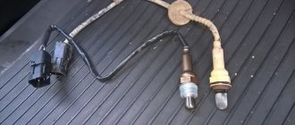
If you study the design of the device, it will include several main components.
- Ceramic tips with protective screens and sampling holes. On the one hand, they serve to take in exhaust, and on the other, outside air. These elements are contained in a middle element inside a ceramic insulator. They are the main working components of the recreation center. These are electrodes from which readings of potentials and their differences are taken.
- Conductive heating element. It should be looked for inside the tips.
- Electrical signal current collector. This component is located in the middle part of the DC.
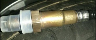
- In addition to the sensitive elements of the tips, all other components of the DC are located inside a metal case equipped with a thread. It is necessary in order to fix the device on the receiving pipe body.
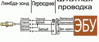
- Modern recreation centers are equipped with wires and a sealing collar. They are called four-wire lambda probes.
- Two white wires are the contacts of the heating system.
- The black wire is the signal wire.
- Black and white striped wiring - grounding.
The other end of the wire, using a plug box, connects the device to the on-board computer. He receives information from the DC about the current state of the air-fuel mixture. Moreover, at idle speed, a request from the ECU to the DC is sent twice per second, and with increasing speed even more often. Depending on the information received, the electronic control unit adjusts the amount of fuel supplied to the engine, creating a rich or lean mixture.
The ECU always strives to ensure that the lambda ratio is as close as possible to the ideal - 14.7:1.
Replacing the lambda probe
In most cases, a part such as a lambda probe cannot be repaired, as evidenced by the statements of many automakers about the impossibility of repair. However, the inflated cost of such a device by official retailers discourages any desire to buy it. The optimal way out of this situation could be a universal sensor, which is much cheaper than its original counterpart and is suitable for almost any make of car. Also, as an alternative, you can buy a sensor that has been in use, but with a warranty period, or a complete exhaust manifold with a lambda probe installed inside it.
However, there are cases when the lambda probe operates with a certain error due to severe contamination due to the deposition of combustion products on it. To make sure that this is really the case, the sensor must be checked by specialists. After checking the lambda probe and confirming that it is fully operational, it is necessary to remove it, clean it and reinstall it.
To disassemble the oxygen level sensor, you need to heat its surface to 50 degrees. After removal, the protective cap is removed from it, and only after that you can start cleaning. Phosphoric acid is recommended as a highly effective cleaner that easily removes even the most stubborn flammable deposits. At the end of the soaking procedure, the lambda probe is rinsed with clean water, thoroughly dried and installed in the socket. At the same time, do not forget to lubricate the threads with a special sealant that ensures complete tightness.
The structure of a car is very complex, and therefore requires constant maintenance of its performance and timely prevention. Therefore, if you suspect a malfunction of the lambda probe, you must immediately diagnose its performance and, if the malfunction is confirmed, replace the lambda probe. In this way, all the most important functions of the vehicle will be maintained at the same level, which will ensure that there are no future problems with the engine and other important elements of the vehicle.
The article discusses the design features of the electronic engine control system (ECM) of cars of the LADA KALINA family. The author presents a diagnostic method for this system on the simplest equipment, error codes of the integrated diagnostic system, their possible causes and elimination sequence.
Features of the composition and design of the computer
Cars of the LADA KALINA family are produced with three types of bodies: VAZ 1118 sedan, VAZ 1119 sedan and VAZ 1117 station wagon. The cars are equipped with a four-cylinder in-line four-stroke engine with injection, fuel distribution and electronic control.
All modifications of the car are equipped with a catalytic exhaust gas converter, which ensures compliance with Euro-3 toxicity standards.
The electrical equipment of the cars is made using a single-wire system, the negative terminals of power supplies and consumers are connected to the “ground” (body and power source) of the car. The rated voltage of the on-board network is 12 V, fuses are used to protect electrical circuits.
LADA KALINA vehicles use a distributed phase injection system: fuel is supplied alternately to each cylinder in accordance with the engine operating order.
The ECM consists of an electronic control unit (controller), sensors that read engine and vehicle operating parameters, and actuators.
The controller is an electronic control unit (ECU) controlled by a microcontroller. The ECU includes several types of memory chips:
— non-volatile flash memory that stores error codes that occur during operation of the engine control unit;
- programmable read-only memory (EPROM), which stores the ECU control program that implements the algorithm for the operation of the car engine.
The ECU controls actuators such as the ignition coil, fuel injectors, idle speed control, oxygen sensor heaters, canister purge valve, and a control relay, one of which is the main relay.
The ECU has a built-in diagnostic system that determines the presence or absence of ECU malfunctions; When a malfunction occurs, the warning light on the instrument panel lights up.
In a car, the ECU is located under the instrument panel at the bottom, it is attached to the heater housing.
In Fig. 1 shows what the controller looks like.
Rice. 1. Appearance of the ECU
The ECM includes a heated mass air flow (MAF) sensor that is located between the air filter and the intake manifold (See Figure 2).
Rice. 2. Appearance of the mass air flow sensor
The mass air flow sensor generates a DC signal, the value of which depends on the amount of air passing through the sensor housing. The sensor output voltage ranges from 1.5 V (forward air flow) to 0.1 V (reverse air flow).
The temperature of the air passing through the mass air flow sensor is measured by a resistive type air temperature sensor, the sensing element of which is installed in the air flow. At the output of the sensor, depending on the air temperature, the DC voltage ranges from 0 to 5 V.
The piezoelectric knock sensor is installed directly on the cylinder block.
Generates an alternating current signal whose amplitude and frequency correspond to the vibration of the engine during operation.
A resistive type throttle position sensor (TPS) is installed on the throttle valve tube; structurally, it is a potentiometer. One pin of the sensor is connected to a reference voltage of 5 V (generated by the ECU), the second pin is connected to the ground of the controller, and a constant voltage proportional to the throttle position is removed from the third.
To allow the controller to read information about the presence of oxygen in the exhaust gases, a control oxygen sensor (OC) is installed, the sensitive element of which is located directly in the exhaust gas flow. The sensor generates a voltage from 50 to 900 mV, which depends on the amount of oxygen in the exhaust gases and on the temperature of the measuring element itself.
For efficient operation of the sensor (its operating temperature is above 300 ° C) and for faster warming up after starting the engine, an electric heater controlled by the controller is included in the sensor design.
DC diagnostics work on the same principle, which measures the presence of oxygen in the exhaust gases immediately after the catalytic converter.
The voltage generated by the hot motor and running converter ranges from 590 to 750 mV.
Oxygen control and diagnostic sensors are installed on the catalyst body: control - in the upper part, diagnostic - in the lower part, directly on the exhaust pipe.
For reliable engine operation and effective reduction of harmful exhaust gases emitted by the engine, it is necessary to maintain an air/fuel ratio of approximately 14.5:1.
The coolant temperature sensor (CTS) is installed in the engine coolant flow on the cylinder head directly on the thermostat. The measuring element of the sensor is a thermistor, the resistance of which varies depending on the temperature of the coolant. The sensor is connected to the controller via a resistor (2 kOhm) included in the ECU.
The crankshaft position sensor (CPS) is installed on the oil pump cover (Fig. 3) at a distance of 1 ± 0.3 mm from the top of the gearbox wheel tooth mounted on the crankshaft. When the main disk rotates, the magnetic flux in the sensor winding changes, in turn, the sensor generates alternating current voltage.
Rice. 3. Appearance of the crankshaft position sensor
The controller determines the position and speed of the motor shaft based on the number and frequency of pulses read.
The Idle Air Controller (IAC) stabilizes the engine speed at idle (Figure 4). This is a stepper motor with two independent windings with a spring-loaded tapered needle. The rotation of the stepper motor is converted into forward movement of the conical needle using a worm gear.
Rice. 4. Appearance of the idle speed control and throttle position sensor
The IAC is mounted on the throttle body in the bypass channel and is controlled directly by the ECU.
The ECM includes an ignition coil, which is a sealed unit consisting of two windings: a primary winding, which is controlled by the controller depending on the specified engine mode. The high voltage secondary windings of the coil are connected to the spark plug wires.
In Fig. 5 shows the ignition coil; it is attached with a bracket to the engine block.
Rice. 5. Appearance of the ignition coil
In recent years, the manufacturer began to equip the car with a new, modernized 16-valve engine equipped with individual ignition coils for each cylinder. Structurally, the single ignition coil is a miniature ignition coil, also controlled by the controller, and the high-voltage part (secondary winding) is connected directly to the spark plug.
Diagnosis of ECU malfunctions and recommendations for their elimination
If the ECM system malfunctions, the standard self-diagnosis system indicates this by turning on a warning light located on the instrument panel.
Intermittent illumination of the warning light indicates a malfunction that could cause serious damage to ECM components. It should be noted that after starting the engine, the warning light should go out, provided that there are no error codes in the controller’s memory. After troubleshooting, the control lamp goes out.
The vehicle's electronic control unit includes various switches, relays, motors, fuses that protect a specific circuit, as well as the wiring itself, connectors, sensors and actuators of the ECM system. All these elements can fail and cause a lot of trouble for the car owner. We analyze the most common faults of the ECU of LADA KALINA cars.
Before you begin troubleshooting, you must carefully study the corresponding circuit to understand its functionality.
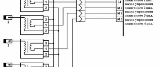
Rice. 6. Electrical diagram of the ignition system of LADA KALINA cars
In Fig. Figure 6 (see Cover 3) shows a diagram of the electrical connections of the ignition system of LADA KALINA cars, where: 1 - oil pressure warning lamp sensor; 2 — pressure gauge for coolant temperature indicator; 3 - additional fuse block; 4 — fuses for the electric fan of the engine cooling system; 5 - electric fuel pump relay; 6 — relay for the electric fan of the engine cooling system; 7 - ignition relay; 8 — relay 2 of the electric fan of the engine cooling system; 9 — relay 3 of the electric fan of the engine cooling system; 10 — electric fan of the engine cooling system; 11 — throttle position sensor; 12 — idle speed regulator; 13 — coolant temperature sensor; 14 — diagnostic block; 15 — electrical wiring lock for the ignition system to the electrical wiring lock for the instrument panel; 16 — solenoid valve for purge of the adsorber; 17 — speed sensor; 18 — electrical wiring lock of the ignition system to electrical wiring lock 2 of the instrument panel; 19 — mass air flow sensor; 20 — crankshaft position sensor; 21 — oxygen sensor; 22 - controller; 23 — rough road sensor; 24 — diagnostic oxygen sensor; 25 — lock of the electrical wiring of the ignition coil to the lock of the electrical wiring of the ignition system; 26 — ignition coils; 27 — electrical wiring lock of the ignition system to the electrical wiring lock of the ignition coil; 28 — candles; 29 — nozzles; 30 - resistor; 31 — pressure sensor in the air conditioning system; 32 — blocks for wiring the ignition system and injector wiring; 33 - phase sensor; 34 - knock sensor.
Rice. 7. Connection diagram of a multimeter to the terminals of the crankshaft position sensor
Failures of electrical equipment often occur for the following reasons: blown fuses and inserts, relay malfunctions, corrosion of connector contacts, low-quality components.
The primary and simplest diagnostic tool for troubleshooting is a multimeter that measures voltage, current and resistance.
Alternatively, you can use a 12V indicator with jumper cables and an open circuit indicator (probe) that includes its own power supply and indicator light/LED.
Also, when diagnosing faults, an electronic oscilloscope can be used, and the ideal option is a specialized diagnostic device or a PC-based device with a specialized program installed that reads and decodes error codes.
Before starting troubleshooting work, it is necessary to check the presence of supply voltage, the quality of the connection to the battery terminals and the integrity of the fuses.
Often ECU malfunctions are related to the reliability of the battery contacts.
Breakage of contacts in the terminals occurs due to insufficient tightening of the connector mounting bolts and oxidation of the contacts. The latter is most often associated with improperly performed scheduled maintenance. The quality of contacts on the terminals is checked visually and using a test lamp.
To prevent oxidation of the terminals, disconnect the connectors from the battery terminals, clean the battery terminals and connectors with fine sandpaper, treat the terminals with electrically conductive grease and restore the connection. Additionally, lubricant can be applied to the terminals on top.
It should be noted that when carrying out work on the vehicle's electrical system, it is necessary to disconnect the terminals from the battery.
The ignition is on, the engine does not start, the fault warning light is always on
1. Check the operation of the immobilizer [1] and its connection (the immobilizer must be in good condition).
2. Check the presence of voltage on the main relay, ignition switch contacts, then check the operation of the ignition switch, main relay, starter (the engine is running, the indicator is constantly on).
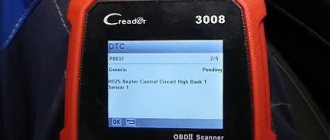
3. Connect the diagnostic device (see Section “Working with the diagnostic device”) and read the error codes (see Table).
4. Check the fuel system.
Table. Self-diagnosis system error codes and their descriptions
Symptoms of a problem
Now regarding the signs of malfunction. There may be several of them. Therefore, carefully monitor the behavior of your VAZ 2114. If you detect one of the signs, immediately take appropriate measures.
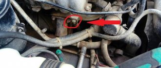
Location of the recreation center
- When gas is low, the power unit begins to operate unstably, may stall, and floating speeds appear;
- The dynamic parameters of the machine have deteriorated significantly;
- Under normal conditions, fuel consumption levels increase excessively;
- A cracking sound is observed in the catalyst zone after the engine is turned off;
- You can hear the characteristic smell of spoiled eggs. Such stench is caused by the ingress of a large volume of gasoline into the catalyst, which is not burned.
If you need to replace the DC, check whether such a probe is installed on your car. On earlier versions of the VAZ 2114, single-wire sensors were installed, and then four-wire sensors appeared. Their price ranges from 1200-3000 rubles, depending on the type of recreation center.
If, when removing the device, you find that there is carbon deposits on the device, but the measuring device shows a slight deviation from the norm, it is not necessary to change the DC. You just need to get rid of the carbon deposits.
To do this, heat the sensor very much and then cool it quickly. This will allow the carbon deposits to crack and fall off. All that remains is to lightly wipe the device with a brush.
What if without a recreation center?
Many people ask whether it is possible to disable the recreation center and how this is done. We categorically cannot recommend doing this, since it leads to serious negative consequences:
- The engine will begin to operate unstably and incorrectly;
- Fuel consumption will increase;
- The composition of the exhaust will deteriorate significantly;
- You will need to reflash the on-board computer.
Therefore, if you find problems with the lambda probe, take the necessary measures to eliminate them. It's not difficult to do it yourself.
In general, a very interesting problem arose and there were also such a bunch of circumstances that in the end I probably spent 2100 rubles in vain... Or maybe not...
The background is this: somewhere around 90,000 km, low-level errors or no signal at all from the oxygen sensor (lambda probe) P0131, P0134 began to appear periodically, and sometimes (rarely, about once a week) the lean mixture error appeared.
The contact is probably bad somewhere, oxidized, etc. I thought. I tried moving it and opening it, but it didn’t help for long. As a result, after googling and reading forums, suspicion fell 100% on the oxygen sensor - they say they don’t last long, 60-80 thousand km, on our gasoline even less. Well, I bought a new sensor, installed it, for about a week everything was fine, no errors, nothing, and then suddenly the situation repeats itself... Hmm, no good, probably a really bad contact. I’ll say right away - I mostly climbed under the hood when the engine was not running
, after about 3-4 thousand mileage, I remember I went to move everything again and I remembered that I hadn’t changed the spark plugs for a long time, I bought fancy 3-electrode Finwalle ones at a sale in a magnet (4 pieces “for only” 350 rubles)
The main symptoms of a malfunctioning lambda probe
The main symptom of a malfunctioning lambda probe is a change in engine operation, since after its failure the quality of the fuel mixture supplied to the combustion chamber deteriorates significantly. The fuel mixture essentially remains uncontrolled, which is unacceptable.
The reason for the lambda probe to fail to operate may be as follows:
- depressurization of the housing;
- penetration of outside air and exhaust gases;
- overheating of the sensor due to poor-quality engine painting or improper operation of the ignition system;
- obsolescence;
- incorrect or intermittent power supply leading to the main control unit;
- mechanical damage due to improper operation of the vehicle.
In all of the above cases, except the last one, the breakdown occurs gradually. Therefore, those car owners who do not know how to check the lambda probe and where it is located most likely will not immediately notice the malfunction. However, for experienced drivers it is not difficult to determine the reason for changes in engine performance.
The gradual failure of the lambda probe can be divided into several stages. At the initial stage, the sensor stops working normally, that is, at certain moments of engine operation, the device stops generating a signal, after which the idle speed destabilizes.
In other words, they begin to fluctuate over a fairly wide range, which ultimately leads to a loss of quality of the fuel mixture. At the same time, the car begins to jerk for no reason, unusual exclamations from the engine are also heard, and the warning light on the instrument cluster should light up. All these anomalous phenomena signal to the car owner that the lambda probe is not working properly.
At the second stage, the sensor stops working altogether on a cold engine, while the car signals the problem to the driver in all possible ways. It is noteworthy that there will be a noticeable drop in power, a slower response to pressing the accelerator pedal and the same pop from under the hood, as well as an unjustified jerk of the car. However, the most significant and extremely dangerous sign of lambda probe failure is engine overheating.
If you completely ignore all previous signals indicating a deterioration in the condition of the lambda probe, its failure is inevitable, which will cause a large number of problems. First of all, the possibility of natural movement will suffer, fuel consumption will increase significantly, and an unpleasant, pungent odor with a pronounced hint of toxicity will appear from the exhaust pipe. In modern automated vehicles, if the oxygen sensor fails, the emergency lock can simply be activated, making subsequent movement of the vehicle impossible. In these cases, only an emergency call to a tow truck can help.
However, the worst-case scenario is depressurization of the sensor, since in this case the movement of the car becomes impossible due to the high probability of engine failure and subsequent expensive repairs. During depressurization, exhaust gases, instead of exiting through the exhaust pipe, enter the support channel of the atmospheric air intake. During engine braking, the lambda probe begins to register an excess of oxygen molecules and urgently sends a large number of negative signals, which completely disables the injection control system.
The main sign of sensor depressurization is loss of power, especially when driving at high speed, a characteristic touch from under the hood when driving, which is accompanied by unpleasant shocks and an unpleasant odor emanating from the exhaust pipe. In addition, depressurization is indicated by visible soot deposits on the exhaust valve body and in the area of the spark plugs.
How to determine a faulty lambda probe is described in the video:
What is an oxygen sensor
An oxygen sensor is an electromechanical device designed to determine the quantitative oxygen content in exhaust gases. Its use is mandatory for all cars with an environmental class above Euro-2.
Why is it needed? The fact is that modern environmental standards require a car to have a minimum content of harmful compounds in its exhaust. It is possible to achieve their reduction only by forming an ideal (stoichiometric) fuel mixture. It is for these purposes that the oxygen sensor, or, as it is also called, the lambda probe, serves. The electronic control unit, having received information about the oxygen content in the exhaust, increases or decreases the amount of air to form the mixture.
How does an oxygen sensor work?
The VAZ-2114 lambda probe has a fairly simple design. It is based on a ceramic element with two electrodes. They are usually coated with zirconium dioxide. One of the electrodes is in contact with air (placed outside the exhaust pipes), and the second is in contact with exhaust gases.
The operating principle of the device is based on the potential difference that occurs between the contacts of the device during engine operation. The electronic control unit sends an electrical impulse to the sensor and analyzes its changes. Based on the increase or decrease in voltage at the probe contacts, the ECU “makes a conclusion” about the amount of oxygen in the exhaust.
Lambda probe: signs of malfunction (VAZ-2114)
Failure of the “fourteenth” oxygen sensor is usually accompanied by the following symptoms:
- the “CHECK” warning light lights up on the instrument panel, warning the driver about an error;
- engine operation at idle speed is unstable (the speed fluctuates, the engine periodically stalls);
- a noticeable decrease in the power and traction characteristics of the power unit;
- the car “jerks” when accelerating;
- increased fuel consumption;
- excess level of toxic substances in exhaust gases (determined by measurement at a specialized station).
What is this error
Car owners need to know that error p0134 is quite common. Its appearance on the instrument panel in the cabin indicates that the connection with the first oxygen sensor has been lost or the transmitted information is incorrect.
Error p0134 is recorded as follows:
- Data that the signal from the lambda probe is weak or completely absent is transmitted to the memory of the car’s on-board computer and recorded.
- If this data does not change within 60 seconds (that is, the signal remains extremely weak or absent), then the information is sent to the ECU.
- 5-10 seconds after information is supplied to the control unit, the Check Engine light turns on on the instrument panel in the cabin.
This is the error indicator
When checking with a scanner, the message “P0134 Oxygen O2 Sensor Circuit No Activity Detected (Bank 1 Sensor 1)” is displayed.
What can the electronic control unit tell you?
If a warning light comes on on the dashboard, indicating errors in engine operation, and its lighting is accompanied by the above problems, it is advisable to test the controller. Today this can be done both at a service station and at home. Of course, if you have a special tester and a laptop (tablet, smartphone) with the appropriate software. When connected, this device will give you codes for possible problems.
For VAZ-2114 vehicles, a faulty lambda probe may indicate its malfunction with the following errors:
- P0130 – incorrect sensor signal;
- P0131 – excessive oxygen level in the exhaust gases;
- P0132 – oxygen content too low;
- P0133 – weak or slow sensor signal;
- P0134 – lack of sensor signal.
Causes
The variety of reasons why this error can occur and generate trouble code P0134 is not that great.
- Breakage or delamination of oxygen contact insulation;
- Short circuit;
- Open circuit.
As a rule, if a malfunction of this nature is associated with an open or short circuit in the circuit, the diagnostics will report not only an error in the inactivity of the oxygen sensor circuit, but will also display a second error P0171 - lean mixture. Since the first lambda probe is the control probe for fuel supply, in the complete absence of a DC signal, the controller reduces the fuel supply to avoid catalyst failure. Therefore, if the self-diagnosis showed only one error, you do not have an open circuit in the sensor or oxidized connector contacts, but in 99% of cases p0134 flies due to internal problems of the sensor.
What can happen to the lambda probe
The lifespan of the lambda probe for the “fourteenth”, declared by the manufacturer, is 80 thousand kilometers. But this does not mean at all that it cannot fail much earlier or last twice as long.
The cause of a malfunction of the VAZ-2114 lambda probe may be:
- overheating of the working element;
- violation of the tightness of the connection between the sensor and the exhaust manifold body;
- clogging of the device contacts due to the use of low-quality fuel, or oil (coolant) getting into gasoline.
Electronic lambda probe test
You can find out the condition of the lambda probe by checking it on professional equipment. An electronic oscilloscope is used for this. Some experts determine the functionality of the oxygen sensor using a multimeter, but it can only confirm or deny the fact of its failure.
The device is checked with the engine running at full speed, since at rest the sensor will not be able to fully transmit the image of its operation. In case of even a slight deviation from the norm, it is recommended to replace the lambda probe.
What kind of lambda probe for VAZ-2114
On the first Samar models of the fourteenth model with one and a half liter engines, sensors 0 258 005 133 were installed. This lambda probe ensured the operation of the power unit in accordance with the requirements of Euro-2 standards.
Since 2004, VAZ-2114 engines began to be equipped with Bosch sensors 0 258 006 537. They differ from the previous modification by the presence of a heating element. It is noteworthy that all oxygen sensors for the “fourteeners” are interchangeable.
Operating principle of a lambda probe
The main task of the lambda probe is to determine the chemical composition of the exhaust gases and the level of oxygen molecules contained in them. This figure should be between 0.1 and 0.3 percent. Uncontrolled excess of this standard value can lead to unpleasant consequences.
As standard, the lambda probe is mounted in the exhaust manifold in the area where the pipes connect, but sometimes there are other installation options. In principle, a different location does not affect the performance of this tool.
Today you can find several versions of the lambda probe: with a two-channel layout and a broadband type. The first type is most often found on older cars from the 1980s, as well as newer economy models. The broadband sensor is typical for modern mid- and high-class cars. Such a sensor is capable of not only accurately determining the deviation from the norm of a certain element, but also promptly balancing the correct ratio.
Thanks to the painstaking work of such sensors, the service life of the vehicle is significantly increased, fuel consumption is reduced and idle stability is increased.
From an electrical point of view, it is worth noting that the oxygen sensor is not able to generate a uniform signal, since this is hampered by its location in the manifold area, since a certain number of operating cycles may occur in the process of reaching the exhaust gases of the device. Thus, we can say that the lambda probe is more likely to react to engine destabilization, which in fact subsequently warns the control unit and takes appropriate measures.
We check the performance of the oxygen sensor with our own hands
How to check the lambda probe on a VAZ-2114 for functionality? Full diagnostics of the device can only be done using an oscilloscope. But it is possible to determine whether it is working or not without complex electronics. To do this, you only need a voltmeter. Connect its “negative” probe to ground, and the “positive” probe to terminal “B” in the sensor connector, without disconnecting it from the on-board network. Turn on the ignition and look at the voltmeter reading. The voltage at the device terminals must match the battery voltage. If it is less, it means there may be a break in the sensor circuit.
If the voltage is okay, check the sensitivity of the working element of the probe. To do this, connect the “negative” probe of the volt sensor, and the “positive” probe to contact “A”. The voltage should be within 0.45 V. If this indicator is exceeded by more than 0.02 V, the sensor must be replaced.
Repair or replacement
Having determined that the lambda probe of the “fourteenth” is faulty, you can either try to repair it or simply replace it. Restoring the sensor involves cleaning its contacts from carbon deposits. This may be the reason why the device has stopped functioning normally.
To begin, the sensor must be unscrewed from the manifold or exhaust pipe. This is not always easy to do. The fact is that its body very often sticks to the specified elements of the exhaust system. In this case, anti-rust liquid (WD-40 or similar) can help. Treat the joint with this liquid and wait half an hour.
When the sensor is unscrewed, pay attention to its body. It is not removable. The contacts that we have to clean are located behind the slots in the case at the bottom.
Important: do not clean contacts mechanically (knife, sandpaper, file, etc.)! This will only aggravate the situation and permanently disable the sensor.
Contacts should only be cleaned using chemicals. For example, orthophosphoric acid. Simply place the lower part of the probe in acid for half an hour, and then dry it on a gas burner.
There is no need to disassemble the sensor by sawing its body. As practice shows, after such a procedure, its performance does not return.
If you decide to replace the lambda probe, buy a new device that meets the specifications from a car dealership and install it in place of the old one. With the ignition on, start the engine, warm it up and check if the CHECK warning light is on.
Ways to deceive the electronic control unit
There are three more ways to restore the engine to its former performance without buying a new oxygen sensor. Without a doubt, they were invented by our craftsmen. And they consist in the fact that it is necessary to mislead the electronic control unit so that it does not notice errors in the operation of the sensor.
The first method is mechanical. To implement this, a special spacer (bushing) is screwed in between the lambda probe and the manifold body (intake pipe). Its use allows you to distance the sensor contacts from the exhaust gases. Thus, the amount of oxygen between them artificially increases, and the electronic control unit “remains satisfied” with the result obtained.
A similar VAZ 2114 lambda probe costs about 500 rubles. And if you have a lathe, you can make it yourself.
The next way to deceive the ECU is electronic. Its essence is to install a primitive converter in the sensor circuit, consisting of one resistor (1 MΩ) soldered into the gap in the blue wire of the connector and one capacitor (1 μF) connected between the blue and white wires. As a result of such a simple deception, the electronic control unit will constantly receive a signal of the required voltage and perceive the operation of the lambda probe as proper.
Alternatively, you can also reflash the controller by changing its software. But it is better to entrust such manipulations with the “brain” of the engine to specialists.
How to extend the life of a lambda probe
To ensure that your oxygen sensor lasts as long as possible, do not neglect the following tips:
- use only high-quality fuel;
- do not allow oil and other process liquids to get into the fuel;
- Monitor the operating temperature of the engine, do not allow it to overheat;
- carry out diagnostics of the oxygen sensor in accordance with the schedule of routine maintenance provided by the manufacturer;
- If you identify signs indicating problems with the lambda probe, do not delay diagnosis.
P0134: No oxygen sensor signal activity. Causes and resolution of the error
Almost every car owner who has some problems during the operation of his car, throughout the entire time, independently eliminates minor breakdowns, or makes the necessary replacements of any parts. But, unfortunately, sometimes the help of a specialist from a car service is necessary, since car enthusiasts do not have enough skills, experience or knowledge in any of the areas regarding the repair of their vehicle. But don’t worry, because our instructions will help you figure it out and do everything yourself.
P0134 Oxygen reader circuit error, the one that goes up to the neutralization element - there is no signal energy. It turns out that lambda probe No. 1 does not function because the 02 B1S1 sensor circuit is in a passive state.
P0134: stands for error code O2 Sensor Circuit No Activity Detected (Bank 1 Sensor 1). This indicates that there are no changes in the information of the oxygen reader.
When diagnosing with a car scanner, the program shows the error: “P0134 Oxygen O2 Sensor Circuit No Activity Detected (Bank 1 Sensor 1).”
Differences from error p0135, which indicates a failure of the heating of the oxygen reading device and affects the driving style of the car, the designation of error p0134 is determined only when the error is read by the program, since it does not have a special effect on the ride quality of the car, the dynamics remain the same, there is no tripping, consumption fuel mixture at the same level, it can only behave poorly during a sharp increase in speed.
What causes the P0134 code to appear?
Coding P0134, a small oxygen sensor ringing value, remains in memory when the engine is running for a little more than a minute, and the information coming from lambda No. 1 to the controlled unit has not been changed over time.
In two words, the tension begins to freeze. And the “CHECK ENGINE” lamp on the socket will light up after five to eight seconds, as a continuous breakdown appears.
What causes the error?
There are not many reasons why this error occurs and fault code p0134 is displayed.
- The insulating elements of the oxygen sensor contacts break or delaminate.
- Small short circuit.
- Break in the chain.
Usually, if a breakdown of this property is associated with an open or short circuit, the diagnosis will indicate not only the error of the inactive oxygen sensor circuit, but will also give another error P0171 - lean mixture. Since the lambda sensor No. 1 controls the supply of the mixture, if the signal from the oxygen sensor is completely absent, the controller will reduce the supply of the fuel mixture to prevent failure of the catalyst device. Therefore, if diagnosing a car produces only one error, you do not have a broken sensor chain, or soured connector contacts, then in 99 percent of cases, p0134 comes out through internal problematic issues in the reading device.
Troubleshooting
In any case, you need to look for a fault in the wires of the oxygen sensor and its connector, then check the sensor bell voltage value. And depending on the technical properties of the lambda, the parameters must be transformed within certain limits. If possible, check the activity with a diagnostic device, warming up the engine to operating degrees, observe the voltage transformations, if there are none, take a multimeter and, after connecting the probe to the required contacts of the reading device, check the functionality of the input signal circuit (measure the positive contact of the sensor and the ground between them). After we disconnect the power supply and check the voltage for about a minute, jumps should be observed within specific limits, depending on the activity of the engine. If this is not observed, or the value is out of range, the oxygen sensor is broken and needs to be replaced.
When replacing the oxygen reading device, do not forget that it is necessary to remove the terminal from the battery device.
After changing the sensor (don’t forget that not all cars have a genuine sensor that can be replaced with a universal one), we reset the error with the program, or by removing the battery terminal for ten minutes and let the car warm up for a couple of minutes under full and partial load, so that we know for sure what the error is eliminated. Because it doesn’t happen very often, but it still happens that P0134 does not happen due to a faulty lambda probe? or cutting off. In such a case, it is necessary to analyze the activity in other mechanisms of the electronic circuit.