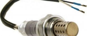
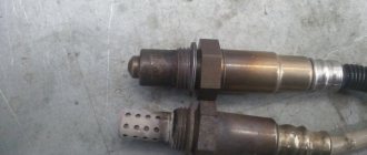
Lambda probe pinout 4 wires
Option 2: - Black wire on the ECU - Gray wire - ground - White wires - “-” and “+” for heating the probe - polarity does not matter. In this case, the white “-” is thrown to ground, and the white “+” to the ignition switch, or to the battery through a relay or something like that. Then it turns out that 2 native contacts remain empty.
What does the oxygen sensor circuit include?
The most common type of probe is zirconium, that is, one where zirconium dioxide acts as a solid-state electrolyte. The zirconium tip is coated with a thin layer of yttrium oxide for improved oxygen conductivity. A layer of platinum is sometimes also applied inside and outside - it copes well with the role of electrodes.
- Signal cable and wire responsible for powering the heater.
- The housing is made of steel, mated to a casing, the thread of which is inserted into the exhaust pipe socket.
- Contact plate for heating wire connection.
- A heating element.
- Electrolyte equipped inside and outside with electrode plates.
- Ceramic thermal insulation.
- The surface responsible for the passage of contact.
- The body is made of metal, through special openings through which exhaust gases pass.
The operating principle is as follows. Inside the working element there is air, the oxygen level in which is taken as a standard provided that the pressure it exerts on the walls when heated is at least 350˚C. Next, the exhaust gases interact with the platinum electrode, and from this moment the permeability becomes not standard, but variable, depending on how much oxygen the exhaust contains. Since oxygen ions tend to move from high to low pressure, a potential difference occurs across the electrodes.
Titanium sensors also operate using a similar algorithm. There are also broadband - LSU sensors that provide signals of higher accuracy.
Lambda probe pinout for 4 wires. Scheme
Most zirconium lambda probes, which are installed on cars starting from 1999, have the same color differentiation of zirconium sensors.
The same is with lambda probes produced using titanium alloys - their pinouts correspond to the same values shown in the table. There is only one difference - there are a lot of cars with zirconium-based lambda probes, titanium ones are rare, but they still exist. Determining the purpose of each lambda probe contact can be determined using special tables that will be presented below. If the color combination of your sensor is identical to the color combination of one of the columns of the tables below (zirconium or titanium lambdas), then the sensor has the specified design and the pinout of the 4-wire lambda probe corresponds to the data indicated in the table.
Oxygen sensors - video
How to check the lambda probe sensor yourself with a multimeter
Every car owner should know this:
Satellite security system Review of satellite anti-theft system, advantages and disadvantages of similar car theft protection systems - is there any point in installing such a device...
| Accelerator pedal position sensor The accelerator pedal sensor (also known as acceleration sensor, gas pedal sensor or throttle position sensor) is designed for electronic… |
| Connection diagrams for PANASONIC car radios Various electrical diagrams for connecting PANASONIC car radios. Several popular models of car radios and standard pinouts for car plugs are presented. These recommendations... |
2014-11-12
Oxygen sensor: four wire colors
For mainstream (narrowband) four-wire oxygen sensors, two wires are used for the signal, and the remaining two are used for the heating circuit. The heating circuit is easy to find - it is two wires of the same color. Those. First we find the same colors, and the purpose (decoding) of the remaining two is determined according to the options typical for Japanese cars:
Black wires of the heating circuit
1. Blue - signal, white - ground (a very common option for Japanese cars, Denso sensors). 2. White - signal, green - ground (Honda).
White wires of the heating circuit
1. Black - signal, gray - ground (typical option for substitutes, used by Bosch sensors and others). 2. Black - signal, red - ground (occasionally happens).
We are, of course, talking about the wires from the sensor itself to the connector. Further colors can be very different.
The Jimny uses Denso's scheme: two black, blue and white.
Classification, device and principle of operation
Sensors are divided into types depending on the material of the active elements, the presence of a heating system, design features and principle of operation. Let's consider the existing types of probes.
Zirconium
For this type of sensor, zirconium dioxide serves as the solid electrolyte of the galvanic system - a ceramic membrane permeable to oxygen ions, which exhibits operating properties at temperatures above 300˚C. The solid-state zirconium tip is coated with a thin layer of yttrium oxide for better permeability of oxygen atoms, and on the outer and inner sides it is partially coated with a thin layer of platinum, which acts as electrodes. Using the example of Fig. 1, let us consider a cross-section of a λ-probe.
- Wires: signal and heater power.
- Heating wire contact plate.
- A steel body connected to a casing that is threaded into the socket of the exhaust pipe opening.
- Zirconium electrolyte with outer and inner platinum electrode plates.
- Heater.
- Ceramic heat insulating element.
- Contact plane.
- Metal housing with holes for flue gases to enter.
Principle of operation
It's pretty simple. In the inner chamber of the working element with a platinum electrode there is ordinary air, which has a standard (reference) oxygen permeability with its own pressure on the walls of the zirconium tip when it is heated to 350-400˚C.
The outer platinum electrode receives exhaust gases, making the permeability variable, depending on the volume of oxygen in these gases. The potential difference on the electrodes appears due to the movement of oxygen ions from the side of higher pressure to the side with lower pressure.
A sharp voltage drop (from approximately 850 mV to 75 mV) when the presence of oxygen in the exhaust changes from a mixture with excess fuel and lack of oxygen (rich, where λ 1), allows measurements to be made with an error of about 5%.
Titanium
The working element of this probe is titanium dioxide. The sensor design is similar to zirconium, but does not require a chamber with a reference air mixture. The operating principle is based on a change in the resistance of the material when the volume fraction of oxygen in the exhaust changes. The more oxygen ions, the greater the resistance that occurs in the working element. For the system to function, a high heating temperature of titanium dioxide (over 600˚C) and a constant power supply to the electronic control unit - 5V are required.
Advantages of titanium probes:
- Durability, small size.
- There is no chamber with a reference comparative mixture, which increases their durability.
- Quickly achieve heating and working condition.
The disadvantages include a higher price than zirconium, which has led to the refusal of car manufacturers to use them in modern models.
Broadband – LSU sensors
With a wide measurement range in areas with different excess air ratios (λ 1), oxygen probes of this design are universally used in a variety of types of engines (gas, diesel, internal combustion with positive ignition) and heating installations. The broadband device more accurately sends a signal to the electronic control unit about the ratio of the presence of oxygen and fuel in the exhaust gases of the internal combustion engine, which allows better control of the level of emissions.
In appearance, the probe is similar to zirconium, but the operating principle is slightly different. The operation of the system is based on maintaining a constant potential difference between the electrodes within 0.45 V, corresponding to an excess air mixture ratio of unity.
The sensor consists of two working elements - zirconium, which performs a measuring function, and an element for introducing or removing oxygen from the system. Between the working elements there is an elongated hole, ranging in size from 20 to 50 microns. Two electrodes are placed in the hole for measuring and adjusting (pumping) the volume fraction of oxygen. A barrier is inserted into the measuring hole, separating it from the exhaust gases and regulating the injection or pumping of oxygen from it. The zirconium element is in contact with the external atmosphere thanks to a small supply channel.
DIY lambda probe emulator circuit
Publication date: January 16, 2022. Category: Automotive equipment.
Lambda probe (also called oxygen controller, O2 sensor, DC) is an integral part of the exhaust system of vehicles that meet EURO-4 environmental standards and higher. This miniature device (usually 2 or more lambda probes are installed) monitors the O2 content in vehicle exhaust mixtures, thereby significantly reducing the emission of toxic waste into the atmosphere.
If the DC is not operating correctly or if the lambda probe is disconnected, the functioning of the power unit may be disrupted, causing the engine to go into emergency mode (the Check Engine light will light up on the panel). To prevent this from happening, the car system can be outsmarted by installing a decoy.
In what systems are they used?
We change the oxygen sensor on a VAZ 2114 with our own hands: features of removing the lambda probe
Oxygen sensors allow you to measure the volume fraction of oxygen in the gases present after fuel combustion in internal combustion engines and boilers operating on solid fuel or methane.
λ-probes are used in instruments that measure the proportion of oxygen in the flue gases of boilers at thermal power plants and other industrial enterprises for the best adjustment of the efficiency of fuel combustion by supplying air to the furnace, depending on the instrument readings.
Sensors are most widely used in the automotive industry for automatically adjusting the supply of gasoline-air mixture to engine cylinders.
Mechanical snag of the lambda probe (“screw-in”)
“Vvertysh” is a bushing made of bronze or heat-resistant steel. The inside of such a “spacer” and its cavities are filled with ceramic chips with a special catalytic coating. Due to this, the exhaust gases are burned faster, which, in turn, leads to different indicators of pulses 1 and 2 DC.
Important! Any snag is installed only on a working lambda probe.
A homemade lambda probe decoy, the diagram of which is presented below, is easy to manufacture. To do this you will need to prepare:
The blende is made on a processing lathe. If there is none, then you can contact a specialist by providing him with a drawing.
The resulting part is compatible with most exhaust systems of both domestic and foreign cars.
Installation of the lambda probe blende is carried out as follows:
- Lift the car onto the overpass.
- Disconnect the negative terminal on the battery.
- Unscrew the first (upper) probe (if there are two of them, then remove the one located between the catalyst and the exhaust manifold).
- Screw the lambda probe into the spacer.
- Reinstall the "advanced" sensor.
- Connect the terminal to the battery.
Healthy! Typically, mechanical blending of the second lambda probe is not performed, since this DC is protected by a catalyst and only controls its condition. The most sensitive is the first sensor, which is installed closest to the collector.
After this, the “Check Engine” system error should disappear. If this method does not work, you can use a more expensive deception.
Instructions for replacing the sensor yourself
Before starting work, you need to prepare materials and tools:
- New probe.
- A wrench or socket that will allow you to unscrew the sensor housing from the manifold. On some cars, you can try to remove the device with a regular 22 mm open-end wrench or a gas adjustable wrench. But the majority of machines require the use of a specialized attachment.
- Extension for nozzle.
- Torque wrench up to 50-100 N/m.
- Protective gloves and sleeves, since work is performed on a heated collector.
- Wrenches for removing protective heat shields and/or manifold.
Lambda probes should be replaced with the same model or a similar one that matches the parameters. You cannot install the first sensor you come across. Before installation, you must carefully study the instructions supplied by the manufacturer.
Approximate sequence of actions when replacing the first probe:
- Warm up the power unit to operating temperature. In this case, thermal expansion of the exhaust system elements occurs, which makes it easier to unscrew the sensor from the manifold or exhaust pipe.
- Turn off the engine.
- Remove the terminal from the battery to eliminate the possibility of the electric cooling fan starting.
- Carefully disconnect the probe connector from the wiring.
- Wear protective gloves and remove the probe wire from the clamps.
- Using the nozzle, unscrew the probe. At this stage, difficulties are possible, since the junction of the probe and the collector becomes clogged with rust and burnt grease. To facilitate the process, local heating with a gas burner can be used, which allows you to burn out the rust. After this, you should try to pull the probe out of place; if the part does not begin to unscrew, repeat the warming up again.
- Wipe the installation area from any remaining old graphite grease.
- Check the presence of standard lubricant on the threads of the new probe. The product may be included in the package in a separate bag. The lubricant is applied in a thin, even layer to the thread. Application to the protective cap is strictly prohibited, as this leads to the formation of hard deposits and deterioration of the probe’s operating parameters. If the car uses a sensor secured with two bolts, then they do not need lubrication.
- Carefully screw the sensor into place by hand until it stops.
- Tighten the probe with a wrench to the required torque. Most manufacturers indicate a force of 40-45 N/m, but it is recommended to check the value in the service literature. If there is no torque wrench, tightening is done by turning the probe 180º after twisting it by hand until it stops.
- Lay the harness along the clamps, secure with clamps if necessary.
- Connect the battery and clear errors from the control unit. Errors can be cleared using a computer or another method (depending on the make and model of the car).
When installing the probe, the tightening torque must be observed. Excessive force leads to destruction of the probe body or breakage of the thread; low torque causes breakthrough of exhaust gases and uneven heating of the part.
Electronic snag
Another way to eliminate problems with the DC is to use an electronic decoy of the lambda probe, the diagram of which is presented below. Since the oxygen sensor transmits a signal to the controller, a decoy circuit connected to the wiring from the sensor to the connector will “crude” the system. Thanks to this, in a situation where the lambda probe is faulty, the power unit will continue to operate correctly.
Healthy! The installation locations for such deception may differ depending on the PBX model. For example, it can be mounted in the central tunnel between the seats, in the dashboard or in the engine compartment.
The decoy circuit is a single-chip microprocessor that analyzes the processes in the catalyst, receives data from the first DC, processes it, converts it to the indicators of the second sensor and issues a corresponding signal to the car processor.
To install this type of snag, you will need a lambda probe connection diagram, which looks like this.
As you can see, there are different pinouts of the lambda probe (4 wires, three and two). The colors of the wires may also vary, most often there are products with 4 pins (2 black, white and blue).
To make a deception device, you will need:
- soldering iron with a fine tip and solder;
- rosin;
- non-polar capacitor with a capacity of 1 µF Y5V, +/- 20%;
- resistor (resistance) 1 mOhm, C1-4 imp, 0.25 W;
- knife and insulating tape.
Healthy! Before installation, it is best to place the circuit in a plastic case and fill it with epoxy.
Next, the electronic snag is mounted on the lambda probe with your own hands as follows:
- Disconnect the negative terminal of the battery.
- “Dissect” the wire that goes from the DC itself to the connector.
- Cut the blue wire and connect it back through the resistor.
- Solder a non-polar capacitor between the white and blue wires.
- Insulate connections.
Below is a do-it-yourself diagram of a lambda probe for pinout into 4 wires.
At the final stage, the following should happen.
Such manipulations should not be performed if you do not have the proper experience. Today, stores offer ready-made decoy circuits that even a novice driver can easily install.
Replacement
Connection wire
Replacing a lambda probe is not at all difficult. The main thing here is to find a device identical to the old one. For this purpose, the sensors have corresponding markings, by which you can easily find an analogue.
- Wait until the engine cools down completely. Make sure the ignition is turned off;
- The old sensor is dismantled with a regular wrench. Just before this, be sure to disconnect the wires going to the lambda probe;
- Next, a new device is installed;
- The new sensor should be screwed in carefully, since excessive force on the wrench may cause the thread to break;
- Reconnect the wires and check the new probe in operation.
As you can see, checking and replacing the oxygen sensor on the VAZ 2110 is quite simple. You don't have to be a professional. Follow the instructions and only use a similar probe, as a device with a different marking simply will not function.
Reflashing the controller
Some particularly sophisticated car owners decide to reflash the control unit, which blocks the processing of signals from the second oxygen sensor. However, it must be taken into account that any changes to the system operation algorithm can lead to irreversible consequences, since returning the factory settings will be almost impossible and costly. Therefore, it is not recommended to perform such manipulations yourself. The same applies to ready-made firmware that is sold on the Internet.
Healthy! When flashing the lambda probes, they are removed.
If you still want to flash the system, then contact a competent specialist who can disable receiving DC data using specialized equipment.
It is also worth considering that almost any intervention in the operation of systems can lead to not the most pleasant consequences.
Oxygen supply life and its malfunctions
The lambda probe is one of the fastest wearing sensors. This is due to the fact that it is constantly in contact with exhaust gases and its resource directly depends on the quality of the fuel and the health of the engine. For example, a zirconium oxygen generator has a service life of about 70-130 thousand kilometers.
Since the operation of both oxygen sensors (upper and lower) is monitored by the OBD-II on-board diagnostic system, if any of them fails, a corresponding error will be recorded, and the “Check Engine” malfunction warning lamp will light up on the instrument panel. In this case, the fault can be diagnosed using a special diagnostic scanner.
Among the budget options, you should pay attention to Scan Tool Pro Black Edition
Scan Tool Pro Black Edition
This Korean-made scanner differs from analogues in its high build quality and the ability to diagnose all components and assemblies of the car, not just the engine. It is also capable of monitoring the readings of all sensors (including oxygen) in real time. The scanner is compatible with all popular diagnostic programs and, knowing the permissible voltage values, you can judge the serviceability of the sensor.
Signal of a working oxygen sensor
When the oxygen sensor is working properly, the signal characteristic is a regular sine wave, demonstrating a switching frequency of at least 8 times within 10 seconds. If the sensor fails, the signal shape will differ from the reference one, or its response to changes in the mixture composition will slow down significantly.
Main malfunctions of the oxygen sensor:
- wear during operation (“aging” of the sensor);
- break in the electrical circuit of the heating element;
- pollution.
All these types of problems can be caused by the use of low-quality fuel, overheating, the addition of various additives, or oils and cleaning agents entering the sensor operating area.
Signs of oxygen failure:
- Indication of a malfunction warning lamp on the instrument panel.
- Loss of power.
- Poor response to the gas pedal.
- Rough engine operation at idle.
What are the consequences after installing decoys?
You need to understand that any deception is installed at the risk of the car owner. If the installation was carried out incorrectly, you may encounter the following problems:
- Due to the fact that the on-board computer cannot regulate fluid injection, engine malfunction may occur.
- If the circuit is not properly soldered, it may damage the wiring.
- In the process of installing the decoy, you can damage the oxygen sensors, after which you will not even know about their malfunction (since you will already have the decoy installed).
- After such interventions (not only during flashing), the on-board computer may fail.
Important Tips
When using this cleaning method at home, always consider the following important nuances.
- Phosphoric acid and various aggressive analogues of this product are dangerous chemicals. When working with them, you should adhere to personal safety rules. Liquids should never get into your eyes, mucous membranes or inside your body.
- For moderate clogs, cleaning the lambda probe with acid may actually take 15-30 minutes. But if a stable and dense layer of soot has formed, then it is better to leave the oxygen sensor in an aggressive environment for a longer time. There is no need to worry, because even a day in a container with phosphoric acid will not damage the core. But the pollution should certainly disappear.
- To make sure the controller is working after cleaning it, you will have to wait a while. The vehicle may not immediately return to its previous operating mode before problems with the oxygen sensor occur. But if, after 10-20 kilometers traveled, fuel consumption does not drop to normal, the car jerks and thick smoke pours out of the exhaust pipe, then it is better to change the sensor. If all symptoms go away soon, you have successfully cleaned the lambda probe correctly.
- If the check engine light on your car comes on again after installing the cleaned controller, then you should not expect the device to restore functionality. This message on the instrument panel clearly indicates that cleaning did not produce any results. You will have to completely replace the oxygen sensor with a new one.
- Some oxygen sensors use double-layer protective caps. If you don’t have a machine, you won’t be able to make a window with a simple file. But this does not mean that it is impossible to clean it. You just have to lower the sensor along with the cap. Cleaning may take a little longer, but often achieves the desired result.
Based on these recommendations and cleaning features, you will be able to do everything correctly. There is no point in giving up trying to resuscitate the lambda probe. This item is really not very cheap, so there is a good opportunity to save on repairing your car.
Lambda probe pinout 4 pins
A modern car is an electromechanical system that consists of many parts and assemblies that are interconnected by a combination of various sensors. These sensors maintain the operating condition of the car and ensure its productive operation. Today in this article we will talk about the oxygen sensor (lambda probe). In particular, we will answer the question of how to check a lambda probe with 4 wires with a tester. This is the most common type of sensor and is quite important. Before you begin studying and testing the performance of the LZ, we recommend that you briefly study its design features, types and principle of operation.
Device
The design of the lambda probe includes the following elements:
- Body made of metal;
- An insulator made from ceramics;
- O-ring with cuffs and wiring;
- Protective cover with ventilation holes;
- A circuit contact through which current is conducted;
- Ceramic tip;
- Filament coil;
- Protective shield with holes that allow gases to escape.
As you may have noticed, the design involves the use of heat-resistant materials. Not surprising, since the oxygen sensor has to operate under extreme temperature loads.
In this case, devices range from single-wire to four-wire.
What is a lambda probe, principle of operation and its types
So, an air sensor is a small device that is installed in the exhaust manifold of any modern car and serves to assess the concentration of residual oxygen in the exhaust gases. Thanks to the readings of this device, the computer unit of your car receives data on the basis of which it prepares a combustible mixture. The lambda probe takes into account the residual oxygen concentration in the burned fuel and sends a signal to the electronics that the newly incoming combustible mixture needs to be either enriched or depleted of air. It goes without saying that any malfunction of the lambda probe may affect the performance of the car’s engine.
Remember! For combustion of 1 kg. mixture of fuel and air, you need to spend about 15 kg . oxygen.
Lambda probe device
A modern air sensor is a small structural device inside which there are a number of interconnected parts.
Lambda probe design
- A metal body with threads. It is designed to fix the sensor in the mounting hole;
- Insulator made of ceramic;
- O-ring seal;
- Conductors;
- Protective shell with hole for ventilation;
- Contact;
- Ceramic tip;
- Electric heater;
- Gas outlet;
- Steel shell.
As a rule, the start of exhaust gas measurements occurs at a temperature of 310-400 degrees . It is at this temperature that the special filler in the sensor becomes electrically conductive. Until the temperature reaches the desired value, the car’s electronic control unit takes readings from other sensors, and only then from the lambda probe. The peculiarity of its operation is that the exhaust gases and atmospheric air are separated by a container with a current-generating composition. As a result of certain chemical effects on this capacity from the exhaust side and from the air side, a difference in oxygen concentration occurs, on the basis of which an electrical potential is generated. The values of this potential are sent to the vehicle control unit.
All oxygen sensors are divided into four types depending on the number of wires in their design:
1. Single-wire; 2. Two-wire; 3. Three-wire; 4. Four-wire.
Types of lambda sensors
All of the above lambda probes come in narrowband and broadband .
What is this?
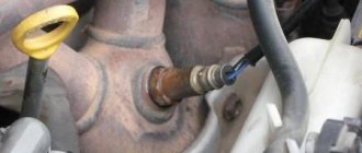
An oxygen sensor or lambda probe for a VAZ 2110 is a device that is located on the exhaust manifold in the exhaust system of your car.
Data transmitted from the device allows the electronic control unit to optimize the composition of the air-fuel mixture. If the mixture entering the combustion chamber turns out to be lean or excessively rich, the sensor reports this, after which the mixture begins to be adjusted.
The main causes of lambda probe malfunctions and the consequences of its breakdown
Once we have defined the concept and operating features of the oxygen sensor, we can conclude that it plays a key function in the normal operation of the internal combustion engine. So what can cause the lambda probe to break down and fail? There are two aspects to this issue: external factors and internal ones, about which read below.
- Coolant or brake fluid leaking into the sensor housing;
- Caring for the sensor with means that are not intended for such purposes;
- Poor quality fuel with excessive lead content;
- Overheating of the sensor, which also happens when using bad fuel.
After the lambda probe fails your car will begin to show certain signs:
- Significant jerks when moving;
- Excessive fuel consumption;
- Poor performance of the catalyst;
- Floating engine speed;
- Excess toxic waste in exhaust gases.
The seriousness of all of the above should prompt the driver to check the lambda probe almost every 10 thousand km. Its complete replacement is desirable after every 40,000 km.
Tips and tricks
At the first signs of malfunction of the lambda sensor (the car begins to jerk sharply when starting to move, the gas pedal does not work so quickly, warning messages should be displayed on the panel, engine overheating during operation, unpleasant toxic gases from the exhaust pipe), you need to decide on some questions:
- Accurate detection of probe malfunction.
- Correct selection of a new sensor.
- You should not be tempted to install a used sensor (its remaining life is unknown) if you want to keep the engine in good condition.
- There is no need to try to disassemble the device; it is sealed and cannot be repaired.
It is advisable to buy an original probe or a universal one (for engines of a certain manufacturer).
Checking a lambda probe with 4 wires with a tester. Methods for checking LP
So, we come to the question that worries every car enthusiast: how to check the lambda probe sensor at home? To do this, you will need a regular tester (multimeter) or voltmeter.
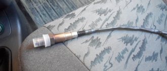
Lambda probe 4 wires
The first step is to warm up the engine, and then measure the resistance on the heater wires. As a rule, these are two white wires, the polarity between which may not be observed. The normal resistance between them should be from 2 to 10 ohms . If this value is different, then the sensor is faulty.
Lambda probe voltage graph
Let's move on. Now you need to connect the negative wire of the tester to the engine housing. In this case, connect the positive contact to the signal wire of the sensor itself. Typically this will be the black wire. With the engine warm, press the gas pedal and accelerate to 3000 rpm . Hold the pedal in this position for about three minutes. At this time, the lambda probe is warmed up. Now you can check whether the oxygen sensor is turned on.
The voltage between the motor housing and the signal (black wire) of the part should fluctuate between 0.2 and 1 volt . For every 10 seconds , the sensor should turn on about 10 times . In cases where the tester shows 0.4-0.5 volts and does not turn on, we can conclude that the lambda probe is faulty.
You also need to know that when you press the gas pedal sharply, the tester should show a voltage of about 1 volt . When the pedal is suddenly released - zero volts .
That's all for us. We hope that your sensor is fully operational and performs its intended functions. If you have any questions, please leave them in the comments.
How to use tables?
Look at the colors of the cable wires coming from the lambda probe. In the columns of the tables there are available color combination options. If the color combination of your sensor matches the color combination of one of the columns of the proposed tables, then your sensor has one design or another. To determine the purpose of each wire, refer to the left column of the selected table.
Example.
Your sensor has 4 wires with the following color combination: 2 brown, 1 purple and 1 beige. The fourth column of the Zirconium Sensor Pinout Table has the same color combination, which means your sensor is zirconium. Next, we turn to the left column of the same table and find out the purpose of each wire: both brown - heating element purple - beige signal - ground (minus) Then we connect the wires by color.
Voltage on the VAZ 2114 oxygen sensor, as well as other technical indicators
Each indicator has its own standard values. If they change, then this is a clear signal of the presence of any malfunctions.
In order to determine a sensor malfunction, you should pay attention to the following signs:
- Increased fuel consumption.
- The appearance of any distinct crackling sounds. They usually occur in the area where the oxygen sensor is located. Most often, crackling sounds occur when the engine is turned off.
- There are problems with the engine at low speeds.
The lambda probe used in standard injection systems cannot detect changes in the mixture composition that differ significantly from 14.7:1.
Checking the lambda probe
Advice. You should also check the oxygen sensor if errors 134 or 131 occur. Their presence can be judged from the information from the car’s dashboard. These errors indicate that the sensor is sending an incorrect signal. This means the problem is with the sensor wiring. Another reason may be due to insufficient grounding of the device on the car body. In some cases, error 132 occurs. It means that the fuel mixture supplied to the car is too lean.
In order to solve any problem related to the device, you should study the pinout diagram. Only after this can you begin checking the device. Where is the oxygen sensor located?
- In models with a 1.5 liter engine, it is located at the very top of the exhaust pipe. The sensor can be located next to the resonator.
- If we are talking about a car with a 1.6-liter engine, then the sensor can be found in the engine compartment. It is usually located on the exhaust manifold of the power unit. It should be taken into account that new models have several oxygen sensors at once. They are located close to each other, so finding them is extremely easy.
Bosch oxygen sensor pinout
How to check the lambda probe and signs of malfunction? Will a Bosch universal fit?
- The car jerks when you drive at low speeds - 1 answer
First of all, when the lambda fails and malfunctions, several tangible consequences appear in the car’s behavior:
- Increased fuel consumption
- Unstable operation of the car engine (jerks)
- The operation of the catalyst is disrupted (toxicity increases)
Then, to check the lambda probe, you can first unscrew it and carry out a visual check (just as a visual check of the spark plugs can tell you a lot).
Several types of lambdas are installed on cars; the sensors can have one, 2, 3, 4, even five wires, but it is worth remembering that in any of the options, one of them is a signal (often black), and the rest are intended for heater (usually they are white).
Symptoms of malfunction
Where is it installed?
Based on the behavior of the car, you can easily determine that the lambda probe has become unusable:
- The car jerks while driving;
- The revolutions are floating;
- The catalyst is not working properly;
- Fuel consumption increases noticeably;
- Exhaust gases contain a large amount of toxins.
What and how can you check the lambda?
To check, you will need a digital voltmeter (preferably an analog voltmeter, since its “sampling” time is much shorter than that of a digital one) and an oscilloscope, if possible, the measurements will be more accurate. Before checking, you should warm up the car since lambda operates correctly at temperatures above 300C°.
First we look for the heating wire:
We start the engine, do not disconnect the lambda connector. We connect the negative probe of the voltmeter (ordinary gauge) to the car body. We “poke” the positive probe on each wire contact and observe the voltmeter reading. When the positive wire of the heater is detected, the voltmeter should show a constant 12 V. Next, using the negative probe of the voltmeter, we try to find the negative wire of the heater. We connect to the remaining contacts of the sensor connector. If a negative contact is detected, the voltmeter will again show 12 V. The remaining wires are signal wires.
General connection rules
Since 1999, cars have typically been equipped with zirconium or titanium oxygen sensors that meet certain standards regarding wire colors. The number of wires is usually four. Below are tables for both probes. In the vast majority of cases, to check you will need the first table - for zirconium sensors, but occasionally you can find titanium ones.
If, during reconciliation, it is revealed that the combination of colors in one of the columns of the table corresponds to the colors of the lambda probe wires of your car, this means that the probe is structurally designed this way, and the pinout should be done in accordance with these data.
Color combinations (zirconium probes)
Color combinations (titanium probes)
Tip for using the table:
- Check the oxygen sensor wires in your car.
- Compare their colors with the columns in the tables.
- If the colors completely match one of them, then this is exactly the design you have and you should build on it.
For example, your lambda probe is equipped with four wires of the following colors: beige, purple and two brown. The same combination is indicated in the fourth column of the first table. This means you have a zirconium device with the same wires and operating principle. Next, we look at the first column of the same table and see that the arrangement of the wires according to the diagram is as follows: the beige one goes to ground (minus), the purple one is responsible for transmitting signal data, and the two brown ones are needed for the operation of the heater. This way you can accurately identify the wires by their shades.
Checking the lambda probe with a tester:
We take an electronic constant voltage millivoltmeter and connect it in parallel with the LZ (“+” “-” to the LZ, - to ground), and the lambda probe must be connected to the controller.
When the engine warms up (5-10 minutes), then you need to look at the voltmeter needle. It should periodically move between 0.2 and 0.8 V (i.e. 200 and 800 mV, and if less than 8 cycles occur in 10 seconds, it’s time to change the LZ. Also replace if the voltage “stands” at 0 .45 V.
When the voltage is always 0.2 or 0.9 V, then there is something wrong with the injection - the mixture is too lean or too rich. Since the oxygen sensor voltage should change all the time and jump from ≈0.2 to 0.9V.
There is another quick way to check the lambda probe . You should do this:
Carefully pierce the positive contact of the tester (black lambda wire), the other contact to ground. With the engine running, the readings should range from 0.1 to 0.9V. Constant readings (for example, 0.2 all the time) or readings that go beyond this range, or fluctuations with a smaller amplitude indicate a malfunction of the probe.
- all the time 0.1 - little oxygen
- all the time 0.9 - a lot of oxygen
- The probe is fine, the problem is something else.
If you have the time and desire to bother, you can conduct several tests on a rich and lean mixture and additionally check the lambda probe sensor .
- Disconnect the oxygen sensor from the block and connect it to a digital voltmeter. Start the car and, by pressing the gas pedal, increase the engine speed to 2500 rpm. Using a device for enriching the fuel mixture, reduce the speed to 200 per minute.
- If your vehicle is equipped with an electronically controlled fuel system, remove the vacuum tube from the fuel pressure regulator. Look at the voltmeter reading. If the instrument needle approaches the 0.9 V mark, it means the lambda probe is in working condition. A malfunction of the sensor is indicated by the lack of response from the voltmeter, and its readings are less than 0.8 V.
- Do a lean mixture test. To do this, take a vacuum tube and provoke an air leak. If the oxygen sensor is working properly, the digital voltmeter reading will be 0.2 V or lower.
- Check the operation of the lambda probe in dynamics. To do this, connect the sensor to the connector of the fuel supply system, and install a voltmeter parallel to it. Increase engine speed to 1500 rpm. The voltmeter readings with a working sensor should be at the level of 0.5 V. Another value indicates a failure of the lambda probe.
Checking the voltage in the heating circuit
To check the presence of voltage in the circuit, you need a voltmeter. We turn on the ignition and connect it with probes to the heater wires (you cannot disconnect the connector, it is better to pierce it with sharp needles). Their voltage should be equal to what the battery produces when the engine is not running (about 12V).
If there is no plus, you need to go through the battery-fuse-sensor circuit, since it always goes directly, but the minus comes from the ECU, so if there is no minus, look at the circuit to the block.
Checking the lambda probe heater
In addition to measuring voltages with a multimeter, you can also measure resistances to check the serviceability of the heater (two white wires), but you will need to switch the tester to Ohms. The documentation for a particular sensor must indicate the nominal resistance (usually it is about 2-10 Ohms), your task is only to check it and draw a conclusion. The video shows this method:
How to properly check a lambda probe with a multimeter with video
How to check the functionality of a lambda probe A lambda probe is designed to analyze vehicle exhaust gases for the amount of oxygen and on modern cars is installed together with the so-called catalyst. An excess of this gas in the air-fuel mixture does not bode well for your car, because the operation of the catalyst directly depends on oxygen. How to check the lambda probe for serviceability with a multimeter? Let's talk about this further.
What is a lambda probe
This is a fairly simple exhaust gas analysis device based on the galvanic effect. It is usually located in the exhaust manifold. On some cars, for example, Lada Kalina, two specific oxygen sensors are installed. It has been noted that the condition of the device is directly related to fuel consumption.
Based on the readings of the oxygen sensor, the engine management system adjusts the composition of the combustible mixture if it becomes leaner. The presence of oxygen changes the electrical potential difference in the exhaust gases, and these changes are detected by the device.
Oxygen sensors from different cars
The lambda probe can only operate in a certain temperature range, so it has a built-in thermal element that turns on when the engine starts.
The oxygen sensor circuit is as follows:
Cross-section of oxygen sensor
Symptoms of a problem
The following symptoms indicate a malfunction of the oxygen sensor:
- The on-board computer reports an excessively rich mixture if there is no reason for this.
- Slow sensor response to changes in mixture composition.
- Misfires.
- Problems with the power supply system.
- External damage to the sensor housing.
- The engine behaves unsteadily at low speeds.
- The car's acceleration dynamics deteriorate.
- The catalyst is heating up.
Checking the oxygen sensor with a multimeter
Diagnostics of a lambda consists of monitoring the voltage of its signal output using a scanner or tester. By changing the quality of the mixture, you can track changes in the readings of the oxygen sensor, which will ultimately give a diagnosis about the serviceability or unsuitability of the latter. But the errors that the ECU shows you may turn out to be a hoax. What can you do, sometimes electronics make mistakes.
To check the oxygen sensor with a multimeter, the engine must be running and warmed up. The crankshaft revolutions according to the tachometer readings should not exceed 3000 per minute. Next, one of the probes of the tester is connected to the probe output, and the other to the “ground” of the car, and with the engine running, an imitation of changes in the composition of the combustible mixture in the cylinders begins. With a working probe, voltage readings will vary from 0.2 to 0.9 volts.
The multimeter is connected to the lambda probe according to this diagram
You can simulate a change in the air-fuel mixture by injecting a small amount of gasoline into the intake manifold or removing the hose from the fuel pressure regulator. In this case, the readings of the device should increase sharply.
How to ring and check the probe (video)
What to do if a breakdown is detected
If the tester readings are 0.4-0.5 and there is no response to changes in the position of the accelerator pedal, the oxygen sensor should be replaced. If there is no voltage at all, check visually and ring the wires going to the probe.
The lambda probe can be compared to the first violin of an orchestra - its condition seriously affects the behavior of the engine and the car as a whole. This part is very capricious, and due to the use of not very high-quality fuel, it will not be long in coming with a breakdown, one of the unpleasant consequences of which will be a sharp increase in the toxicity of exhaust gases.