Author: Evgeny Zhivoglyadov. Date of publication: December 20, 2016. Category: Automotive equipment.
A lambda probe is an O2 concentration sensor (or, more simply, an oxygen sensor) that allows you to estimate the volume of unburned oxygen contained in the exhaust gases. These indicators are extremely important, since by maintaining certain proportions of fuel and air, the most efficient combustion of the air-fuel mixture occurs. The best ratio is 14.7 parts oxygen to 1 part gasoline. If this ratio is violated, the mixture will be lean or, conversely, enriched, which, in turn, will affect fuel consumption and engine power.
Although outwardly the oxygen sensor does not look like a “vital” part, it performs a very important function, therefore any malfunction of the lambda probe, the “symptoms” of which we will consider, must be corrected immediately.
Purpose and principle of operation
A lambda probe is a device designed to monitor the composition of exhaust gases. It is used to determine the amount of oxygen remaining after fuel combustion, and the resulting data is transmitted via signal wires to the vehicle's ECU. What is it for?
The fact is that the operation of the exhaust gas and fuel systems are closely interconnected.
The connecting link in this chain is the electronic control unit, which not only receives data from the oxygen sensor in the form of electrical impulses, but also transmits a reference voltage of 0.45 volts to its signal pin (this is important).
The ECU, receiving data from the oxygen sensor, adjusts, depending on the engine operating modes (cold, warm, under load and without it, etc.), the quality of the air-fuel mixture entering the engine cylinders, which can be enriched, poor, depleted, etc. The adjustment occurs by changing the opening time of the fuel injectors.
The correct ratio of fuel and air for certain engine operating conditions under which the fuel mixture burns completely is called the stoichiometric air-fuel mixture.
There is also such a thing as excess air coefficient or lambda level.
Under ideal conditions, when all proportions of fuel and air are correct (14.7 parts of air and 1 part of fuel), this coefficient is equal to 1.
If the mixture is lean (15:1 and above), then the lambda level will be greater than 1, if rich (below 14:1), it will be less.
Let's imagine that the lambda probe is faulty and transmits erroneous data to the ECU. As a result, an incorrect air-fuel mixture will be formed for different engine operating modes, which will result in at least high fuel consumption and loss of power.
Next comes the environmental component, without which modern cars are impossible; we are talking about the catalytic converter.
When fuel burns, a number of toxic components are formed, an increased amount of which in the exhaust gases negatively affects the efficiency of the catalyst.
The main toxic substances include:
- Unburnt hydrocarbons - CH;
- Carbon monoxide and oxygen oxide - CO;
- Nitric oxide – Nox.
Errors in the operation of the lambda probe, and as a result, improper combustion of fuel, lead to an increase in the content of harmful substances in the exhaust gases, and the catalyst is no longer able to cope with this amount.
There is such a thing as a “slow sensor”, this is when its response time exceeds 120 mS and for this reason the ECU does not have time to prepare the correct fuel mixture, hence the increased toxicity of exhaust gases. But more on that below.
It turns out that the lambda probe is an important device, the operation of which determines how correctly the stoichiometric composition of the air-fuel mixture will be formed under certain operating modes of the power unit.
When it is working properly, the error in the formation of the stoichiometric composition is ±1% and this is very important, and when it is not, this figure increases.
Checking the voltage in the sensor heating circuit
It is generally accepted that the optimal voltage in the oxygen sensor heating circuit is 12.45V.
To check the voltage in the oxygen sensor heating circuit, we need a voltmeter.
- Turn on the car ignition
- We pierce the wires with sharp probes or stick the probes from the voltmeter into the connectors of the wire going to the oxygen sensor.
- We measure the voltage.
The voltage on these wires should be equal to the battery voltage, approximately 12.45V. The plus usually comes to the oxygen sensor heaters directly through the fuses, and the minus is supplied from the engine control unit. Therefore, if there is no positive signal coming to the oxygen sensor heater, then look at the circuit, battery, fuse and oxygen sensor. By the way, some car models may have a relay in this circuit. But if there is no minus, then look at the entire circuit up to the control unit. Perhaps contact has been lost in some connector, or the control unit for some reason does not see the minus.
Types of sensors and temperature conditions of their operation
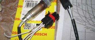
There are two types of oxygen sensors on the market – titanium and zirconium.
The first are made on the basis of titanium dioxide, and the second - on zirconium dioxide.
They are distinguished from each other only by design features; the operating principle is the same.
Titanium sensors have hardly been used lately; they were previously installed on some brands of cars, but are now very rare. Zirconium, on the contrary, has become widespread.
The basis of the device is a ceramic element made of the above-mentioned zirconium dioxide (ZrO2) or titanium dioxide (Tio2), coated with a platinum mesh.
One part of the element is located in the exhaust pipe and is in contact with the exhaust gases, and the other is outside, in contact with atmospheric air through the wire connections.
The temperature at which the lambda probe begins to function varies from 300 to 400 °C, the dangerous limit is 900 - 1000 °C, beyond which the device can overheat and fail. Operating temperature when moving is about 600 °C.
In modern lambda probes, but not all, a heating element is structurally provided, which, when starting the engine on a cold one, will warm the device to an operating temperature of 300 - 400 ° C.
A distinctive feature is the presence of three or four wires, two of which are white (on Japanese cars they can be black) going to the heater.
Such devices can be installed in the exhaust pipe at a considerable distance from the engine, since they do not require intense heating by exhaust gases.
There are no heaters in two or one-wire oxygen sensors, so they are installed as close to the engine as possible, usually in the exhaust manifold, but so that the lambda probe does not fail due to overheating.
For many types of sensors, especially those installed on German cars, but except for Japanese ones, the black wire is the signal wire, and the gray (may not always be) is the signal ground.
On oxygen sensors installed on Japanese cars, the wires have an individual color scheme for each model, so this point needs to be clarified each time.
But there is still one plus: lambda probes, which replace failed analogues, apply only to Japanese cars, have a constant color scheme of wires: the signal signal is blue, not black, the signal ground is white, not gray, and for the heater There are two black wires, not white as usual.
Why exactly 300 °C? It is after this indicator is exceeded that the ceramic element of the device, which can safely be called a solid electrolyte, begins to pass oxygen ions through itself, which collect on the platinum electrode grid.
Imagine two 5-liter containers (canisters) filled with water, standing on the same level and connected to each other by a hose, in the middle of which there is a faucet.
If you just open the faucet, where will the water flow? That's right, nowhere. And if you lift one of the canisters, where? That's right, into the canister that is located below.
A similar principle works in the case of a lambda probe. Opening the tap means the temperature on the ceramic element exceeds 300 °C.
And the flow of oxygen ions through it is ensured by the formation of a potential difference at its ends (raising one or the other canister), the greater the difference, the stronger the voltage (the higher the capacity, the stronger the water flows).
On the side of the sensor that is in contact with atmospheric air (reference), the oxygen content is small and, as a rule, changes only when the vehicle’s operating conditions change (mountains, quarries, etc.), the potential there is small, but it is constantly present.
And on the side of the device that is screwed into the exhaust pipe, the volume of oxygen can vary from small to significant.
But you need to understand that a small amount of O2 in exhaust gases is considered normal, since this ensures complete combustion of the fuel in the exhaust manifold and protects the catalyst in the event of a strong over-enrichment of the fuel mixture (unburned fuel is thrown into the manifold and burns out there).
If the amount of O2 in the exhaust gases is equal to the oxygen contained in the atmosphere, then there will be no potential difference (if this is associated with canisters, then they will be at the same level), and the reference voltage coming from the control unit will be exactly 0.45 volts - level lambda is equal to 1.
Let's say the volume of oxygen in the exhaust gases is significantly lower than atmospheric.
Due to the potential difference, an electric current is formed that flows from the inside of the galvanic cell, in contact with the reference air, to the outside (the “+” value). Its value increases the reference voltage from 0.45 volts from 0.5 to 0.8-0.9.
The ECU sees that the mixture is rich (lambda level less than 1) and makes adjustments.
If the oxygen level in the exhaust gases is high (more than atmospheric), then the potential difference will change, the electric current will flow in the other direction (the “-” value), reducing the reference voltage to 0.1 - 0.3 volts. The ECU will see that the fuel mixture entering the cylinders is lean - the lambda level is greater than 1.
Varieties
Lambda sensors are divided into three groups:
- Zirconium. This model is the most common. The device is based on zirconium dioxide. It has a ceramic tip that operates at temperatures up to 350 degrees. Fast heating is provided by the built-in heating parts with ceramic insulator. These devices are divided into 1, 2, 3 and 4-wire.
- Titanium. In this embodiment, the sensor tip is made of titanium dioxide. It has practically no external differences from zirconium, but its operating condition is at a temperature of 700 degrees. They are rarely found on cars because they are complex, have a considerable price tag and are highly sensitive to temperature changes.
- Broadband. This sensor differs from the above in the presence of two cells. The first is a measuring station and the second is a pumping station.
Device types
Zirconium oxygen sensors (we are missing titanium ones) come in two types - threshold and broadband.
It is not easy to check the latest types of devices using conventional methods, since they are complex in design and are installed on the latest car models. The connection diagram is shown below.
For more details on what a lambda probe is, the evolution of its development, what types there are, read here; we will not dwell on this in this material.
Differences and interchangeability of titanium and zirconium lambda
This concerns the differences between titanium and zirconium lambdas. Their work is based on different principles. Zirconium generates EMF when residual oxygen is detected in the exhaust gases.
Titanium lambda changes its resistance when it detects residual oxygen in the exhaust gases. In accordance with this, their inclusion in the on-board network is different.
Connecting zirconium through a connector in which two pins are heating, one pin is a signal (voltage in volts from 0.1 V to 0.9 V depending on the amount of oxygen in the exhaust gases) and one pin is lambda mass.
Connecting titanium through a connector in which two pins are heating, one pin is a lambda signal (voltage in volts from 0.1 V to 0.9 V, which changes depending on the change in lambda resistance from the amount of oxygen in the exhaust gases) and one pin is reference voltage +1V, which is supplied to the lambda from the ECU. The output signal of the lambda, whether zirconium or titanium, is always a voltage that is compared in the ECU with a reference voltage on a comparator equal to 0.45V.
CONCLUSION: Replacing a titanium lambda with a zirconium one is possible without the use of any additional electronic devices. In this case, you need to use a three-wire zirconium lambda.
It is possible to use a four-wire lambda, but you need to check whether the ground wire connects to the ground of the lambda; if it does, you can cut it off; if it doesn’t, then connect it to the ground of the car.
Warming up the probe
You can also use a multimeter to check the sensitivity of the oxygen sensor tip. To do this, you need to start the car and warm up the engine to 70–80oC. The subsequent algorithm will be like this:
- Bring the engine to 3000 rpm and record this indicator for 2-3 minutes until the sensor warms up.
- Connect the negative probe of the multimeter to the ground of the machine, connect the other to the output of the sensor.
- Examine the data on the tester: it should vary from 0.2 to 1 V and change 10 times per second.
- Press the gas pedal to the floor and quickly release it. A working sensor will produce a value of 1 V, after which it will sharply drop to zero. If the numbers on the display do not change when you operate the pedal and show 0.4–0.5 V, the sensor requires replacement.
If there is no voltage at all, you should check the wiring. To do this, you need to “test” with a multimeter all the wires connecting the relay to the ignition switch.
Symptoms of a problem
Signs of a malfunctioning lambda probe may be the following:
- Fuel consumption increases;
- Engine speed “floats” at idle;
- Failures in the operation of the catalyst, strong uncharacteristic heating of the device, crackling after stopping, increased level of toxicity in the exhaust gases (sharp unpleasant odor);
- “SNESK ENGINE” appears on the instrument panel.
If the lambda probe does not work, how does the car behave?
- The engine is running unsteadily;
- The acceleration dynamics have disappeared and the car jerks.
Unfortunately, these signs can also indicate other problems. But it is recommended to start checking with the oxygen sensor, at least with its external inspection.
Detailed information on this topic can be found here.
Checking with a diagnostic tool
The question of how to check the oxygen sensor lambda probe arises when the engine begins to show the driver any malfunctions that have appeared. You can quickly diagnose a breakdown using a special scanner. Computer diagnostics will not only show the fault, but also indicate what it is. The verification accuracy will be 90%. If after checking it turns out that the error is in the λ-probe, then it will have to be replaced. But there are situations when the device has nothing to do with it, and the problem is hidden in another element.
After diagnostics, it is recommended to still inspect the oxygen sensor, even if the scanner indicated a different error. Sometimes drivers change the sensor to a new one, but then see that the problem remains. To confirm the error, you should contact a specialized auto center.
Reasons for failure
The causes of lambda probe failure may be the following:
- Broken wires going to the sensor, poor contact;
- Mechanical damage leading to deformation of the device and, as a consequence, destruction of the galvanic element;
- Overheating of the sensor as a result of malfunctions in the fuel and ignition systems or improper engine tuning;
- Coking of the top layer with a platinum coating, as a result of which oxygen ions are not captured by the sensor. Occurs due to wear of parts of the cylinder-piston group and the release of a large amount of oil into the manifold or other reasons (see below);
- Coking of the injector nozzle as a result of which the needle does not completely sit in its place and does not block the hole. For this reason, fuel constantly penetrates into the cylinders, regardless of the stroke; there is an excess of gasoline, which, as a result of combustion, releases a large volume of carbon monoxide, which, in turn, settles in the form of soot on the working surface of the oxygen sensor;
- The use of poor fuel leads to the formation of shiny lead inclusions on the platinum surface, which block the access of oxygen ions to the galvanic cell. A harbinger of a problem is a deviation in the color of smoke from the exhaust pipe from the norm;
- Penetration of hot exhaust gases into the lambda probe as a result of depressurization of its housing;
- Coolant entering the engine cylinders, a sign of white smoke from the exhaust pipe, as a result of which deposits also appear on the ceramic element, interfering with the interaction of oxygen ions with the platinum coating;
- Natural wear and tear - the lambda probe needs to be replaced in a timely manner. After 50,000 - 70,000 km - unheated devices, after 100,000 km - heated ones. Planar ones can be changed after 150,000.
External inspection of the sensor
So, an external study of the oxygen sensor will consist of several steps:
- Check the external part that is located outside the catalyst. There should be no melted areas, breaks or closed contacts.
- Unscrew the sensor from the catalyst and examine the lower part, usually hidden in the catalyst. Soot spots on it indicate that the fuel is too concentrated, the engine and valves are close to wear, or there is a leak in the exhaust system. Gray deposits indicate a high lead content in the fuel.
Checking the lambda probe for serviceability
There are several ways to check, you can do everything yourself, without going to a car service.
Lambda probe can be checked:
- Simple external inspection;
- Using an analog or digital voltmeter;
- When using a tester, also known as a multimeter, it is better to take an analog one, it is more informative;
- Using an oscilloscope or motor tester.
IMPORTANT: the input resistance of the above devices should not be less than 1 megaohm.
Visual inspection
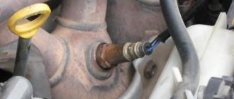
Finding the oxygen sensor is not difficult; it is located on the exhaust pipe closer to the manifold. There can be two of them, one before the catalyst, the second after and connected through the controller.
First, inspect the integrity of the wires leading to the device and how tightly the contacts fit.
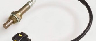
Unscrew the lambda probe from the exhaust pipe and inspect it. The presence of deposits in the form of soot, white, gray, or shiny plaques should suggest that before checking the lambda probe, it needs to be cleaned.
If the device is deformed, it must be replaced immediately; read the topic - how to replace a lambda probe.
Further testing can be carried out using instruments, but you need to understand that, for example, a voltmeter has limited functionality and it is impossible to measure resistance and current, so it is better to immediately acquire a multimeter or other similar tester with advanced capabilities.
Check with a voltmeter and multimeter
A common case is when the lambda probe has four wires. Two are signal ones, and two go to the heater.
The pinout of two, three and four wire lambda probes is shown below.
First you need to check the reference voltage, since this can be done with the engine not running.
Turn on the ignition, take a voltmeter, set the switch to 2 or 20V. We find two signal wires (how to do this is described below) and connect a voltmeter to them, the readings should be in the range of 0.45 - 0.50 volts. These measurements can also be made using a multimeter.
ATTENTION: three wired oxygen sensors do not have a signal ground wire, so we connect the negative wire of the voltmeter (multimeter) to the car body.
Next, we start the car and while the oxygen sensor is warming up (it is checked only after warming up to more than 300 ° C), we check the heater (voltage and resistance).
IMPORTANT: the check must begin with the heater, and then the entire device. The fact is that if there is no power at the heater connector, the sensor may either not work at all, or work very poorly, inadequately and with delays.
We need to check whether 12V voltage is supplied to it; this can be done by finding the necessary wires by color (see pinout above). On most sensors they are white.
We take a voltmeter and check the voltage, everything is simple. This can be done even simpler, turn on the ignition without starting the car, but the resulting measurement result must be compared with the voltage at the battery terminals.
But there are situations when the wiring is so worn out and discolored that it is impossible to determine its color.
Therefore, we take a voltmeter or multimeter, connect the negative wire to the car body, and touch each wire with the positive wire in turn until 12 or a figure close to it appears on the voltmeter.
This way you can find the positive wire of the heater. To search for the negative one, without disconnecting the voltmeter contact from the found positive wire, we alternately connect the second end to the remaining three until a figure close to 12 appears on the voltmeter, as in the first case.
We remember the position of the signal wires and those going to the heater.
If no voltage was detected on the positive wire, check its condition. Typically it is connected directly to the fuse box.
If the negative wire is not working, then it’s more complicated, it goes to the ECU, if there is no break and it rings, then the problem may be in the control unit.
You will also need to measure the resistance of the heater; for this you will need a multimeter. Measurements can also be taken on a removed O2 sensor without a car.
The standard value is from 2 to 10 Ohms, but for each brand of car it can vary greatly; standards of 4.5 - 6 Ohms are often found.
- Take a multimeter and switch it to resistance measurement mode;
- We connect the device to the heater wires;
- We take measurements.
If the resistance is not normal or the number on the device is 1 and nothing happens, then there is an open circuit in the circuit, change the 02 sensor.
We check the operation of the lambda probe through the signal wires
We will check the lambda probe with 4 wires. For this it is better to use a multimeter. The engine is already warmed up, if not, then start the car and let it idle for 5-10 minutes.
We need the ceramic element to warm up and the ECU feedback modes with the oxygen sensor and fuel supply control to turn on, and this happens after the engine has warmed up to 60-700C.
You cannot disconnect the oxygen sensor from the block; to connect to the wires you need to use sharp needles at the ends of the multimeter wires.
Connect the tester to the signal wires in parallel - plus to “+”, minus to “-”, the engine should run.
Pay attention to the voltage indicator, if it is equal to the reference 0.45V and the number is constant, then the lambda probe is faulty.
If the voltage cyclically jumps in the range from 0.1 to 0.9 volts with a frequency of 1.5 - 2 times per second, then the lambda probe is working, otherwise it must be replaced.
If the readings hover either at the bottom (0.1 - 0.3V) or at the top (0.8-0.9V), then the feedback mode may not have turned on yet, which is activated after the engine warms up to 60 - 70 degrees Celsius. Those. The sensor itself has already warmed up, but the mode has not yet been activated.
There is another way to connect a multimeter to an oxygen sensor. Press the negative wire to the body (ground), and the positive wire using a needle through an elastic band to the black wire (positive). Take readings.
What other readings can the multimeter give and what do they mean?
A constant value of 0.8 - 0.9 volts indicates that the fuel mixture is constantly enriched (high-calorie), and there is little oxygen.
This will be indicated by a number of other signs (popping sounds in the muffler, the color of the smoke from the exhaust pipe has changed, and so on.
The causes of the problem should immediately be sought in:
- dirty air filter;
- ignition and fuel system adjustments;
- incorrect operation of injectors (fuel is pouring);
- failure of the air flow sensor;
- improper operation of the economizer;
- other reasons.
If the multimeter readings remain unchanged within 0.1-0.2 volts, then the mixture is constantly lean (a lot of oxygen, 15-17 kg per 1 kg of gasoline). Or, conversely, oxygen is normal, but little gasoline is supplied, with the same ratio of 17 to 1.
There are many reasons for excess air in the cylinders, first of all, you need to look at the exhaust manifold gaskets, whether the brake booster diaphragm is torn, whether the crankcase ventilation system is working correctly (check whether the oil filler plug is screwed in tightly, whether the oil dipstick is inserted tightly - air should not get into crankcase from outside).
If you suspect that there is not enough fuel supplied, then remember the last time the injectors were cleaned or the fuel filter was changed. Pay attention to the fuel pump, most likely its service life is coming to an end and it is working at its limit.
There may be other faults, the diagnosis of which requires a professional approach.
You can check it in another way.
We carry out tests for rich and lean fuel mixtures
To perform a rich fuel mixture test, do the following:
- It is better to do the test on an already warmed up engine and with a partner;
- Disconnect all wires from the sensor, while it should be in its normal place;
- Connect a multimeter to the lambda probe (in 2 or 20 volt modes);
- Start the engine and increase the crankshaft speed to 2600 per minute;
- Reduce the speed sharply and immediately disconnect the pipe from the vacuum pressure regulator, i.e., artificial enrichment of the fuel occurs;
- Record the readings of the multimeter, they should be within 0.7 - 0.9 volts. If there are no dynamics of changes or the numbers are far from those indicated above, it means that the lambda probe is faulty.
Lean mixture check:
- With the car running, take the end of the already removed vacuum pressure regulator tube and create an air leak in it using any convenient method (artificially lean the mixture);
- At the same time, measure the readings of the multimeter, they should be within 0.1 - 0.2 volts. In this case, the readings should change in less than 1 second.
How to conduct a test for dynamic operating modes is shown below.
Chevrolet aveo | checking the condition and replacing the oxygen sensor (l-probe) | Chevrolet Aveo
Checking the condition and replacing the oxygen sensor (l-probe)
general information
An l-probe located in the engine exhaust tract monitors the oxygen content in the exhaust gas flow. When O2 molecules come into contact with the sensitive element of the probe, the sensor generates an amplitude signal in the range from 0.1 to 0.9 V, depending on the oxygen concentration. Moreover, a value of 0.1 V corresponds to a high O2 content (lean mixture), and a value of 0.9 V corresponds to a low content (rich mixture). The upstream oxygen sensor supplies the PCM with information about the residual O2 content in the exhaust system. The RCM continuously monitors the signal coming from the oxygen sensor, if necessary, issuing commands to adjust the composition of the air-fuel mixture by changing the duration of opening of the injection injectors. The optimal ratio of components of the combustible mixture, guaranteeing minimum fuel consumption with the most efficient functioning of the catalytic converter, is 14.7 parts of air to 1 part of fuel - it is precisely this that the control module tries to constantly maintain, focusing on the information received from the l-probe.
The lower flow l-probe does not affect the process of assembling the air-fuel mixture control module. The design and principle of operation of the sensor is identical to the upstream one. By comparing the oxygen levels in the exhaust tract sections above and below the catalytic converter, the PCM determines the operating efficiency of the latter. Note: For 1993 and 1994 models. issue Only one oxygen sensor is used (upstream). On models from 1995. There are two upper-flow l-probes (one for each of the cylinder banks) and one lower-flow L-probe.
It should be noted that the oxygen sensor is capable of generating a signal voltage only when warmed up to normal operating temperature (318 C). While the sensor is in a cold state, the PCM operates in OPEN LOOP mode, controlling the composition of the air-fuel mixture based on the basic parameters embedded in it. The proper functioning of the oxygen sensor depends on the fulfillment of a combination of certain specific conditions:
a) Electrical parameters: The stability of the low-voltage amplitude signal generated by the sensor largely depends on the quality of the contact connections of the l-probe circuit, which should be checked first in case of problems; b) Outside air supply: The l-probe is designed to allow free circulation of outside air inside the sensor. When installing the probe, always check the patency of the air passages; c) Operating temperature: The PCM begins to respond to information received from the l-probe only after the sensor has warmed up to normal operating temperature (about 320 C). This fact should not be overlooked when checking the proper functioning of the probe; d) Fuel quality: Proper functioning of the l-probe becomes possible only if UNLEADED fuel is used to refuel the vehicle!
In addition to the conditions listed in the previous paragraph, some special precautions should be taken when servicing the l-probe:
a) The oxygen sensor is equipped with a piece of electrical wiring, equipped with a contact plug, tightly mounted into it, attempts to disconnect which may lead to irreversible failure of the probe; b) Try not to allow dirt or grease to get into the sensor louvers or its electrical connector; c) Do not use any solvents to clean the oxygen sensor; d) Handle the l-probe with extreme care, do not drop it and try not to shake it off; e) The silicone protective cover must be placed on the sensor in a strictly defined manner so as not to be melted and not to interfere with the proper functioning of the probe.
If the l-probe or its circuit malfunctions, the PCM goes into open-loop mode, ignoring information received from the sensors and maintaining the composition of the air-fuel mixture at a certain specified level, ensuring sufficient engine efficiency.
EXAMINATION
REPLACEMENT
Check with an oscilloscope or motor tester
The main advantage of checking the O2 sensor with an oscilloscope is to record the period of time during which the output voltage changes.
You cannot take such readings with a voltmeter or multimeter.
Even the vehicle control system is not able to detect a slow response of the lambda probe to changes in the volume of oxygen in the exhaust gases, therefore, with such a malfunction, the likelihood of “CHECK ENGINE” appearing on the instrument panel is minimal.
Although cars produced recently already have ECUs installed that cope with this task.
The standard indicator of voltage change is 120 mSec and no more. If the reaction time exceeds the standard (the sensor is slow), then it looks like this on the graph.
In this case, you need to check the lambda probe for coking; if this does not help, it means that the ceramic element has aged.
The graph below shows how slowly it responds when you press the gas pedal hard.
The correct operation of the lambda probe is shown in the graph below.
Here you can see that the upper voltage limit does not exceed 0.8 volts, and the lower one does not go beyond 0.1V. Temporary indicators are also normal.
If you look at another chart, you can see a different situation here.
Here the lower limit has gone beyond the 0.1V mark, and this is unacceptable, which means the lambda probe is faulty. “CHECK ENGINE” will appear on the instrument panel.
On-board system check
If the car has an ECU, troubleshooting can be greatly simplified. It is worth paying attention to the “Check Engine” indicator, which often warns of problems with the lambda probe. To clarify the cause of the signal, just connect an auto scanner to the on-board computer.
Errors related to the oxygen sensor will include:
- P0130: The sensor is sending incorrect data;
- P0131: Signal too weak;
- P0132: signal too strong;
- P0133: CD responds slowly;
- P0134: the sensor does not give a signal at all;
- P0135: The first sensor heater does not function;
- P0136: the second sensor has shorted;
- P0137: KD2 reacts slowly;
- P0138: KD2 reacts too quickly;
- P0140: open circuit KD2;
- P0141: The second sensor heater is faulty;
- P1102: low pressure heater resistance;
- P1115: The circuit is damaged, data cannot be read.
How is the verification carried out?
Connect the oscilloscope to the signal wire, you already know how to find it.
Start the car and warm it up to 60 - 700C. During this time, the O2 sensor will warm up and the feedback mode will turn on.
As the device warms up, you will see how the lambda probe generates a small current within 1 volt.
As the lambda warms up, the voltage level will increase (also within the range of up to 1V), and as it reaches an operating temperature of 300 - 400 0C, it begins to oscillate.
On a warm engine, go to the mode 2500 - 3000 rpm, if the lambda is working properly, the following diagram will appear on the device.
When the gas is suddenly lowered, the mixture should become richer for some time; it looks like this in the diagram.
At idle, the mixture first goes lean.
And then go into the mode of uncertain oscillations.
So, it is checked:
- Warm-up time - after how long the lambda reaches operating mode;
- At engine speeds of 2000 - 3000, the following picture is checked.
If the graph shows that the lambda is stuck in the lower or upper position, i.e. gives a constantly low or high signal level, this means that the oxygen sensor needs to be changed. But provided that the engine is warmed up, and the external inspection gave a positive result.
If you see a picture like the one shown below, then most likely the lambda probe has failed due to overheating.
How the sensor works
Exhaust gases pass through the sensor, and clean air from the atmosphere enters it. Due to the different oxidizing properties of clean air and exhaust gases, a potential difference appears. These readings are sent to the ECU.
Hidden inside the sensor are a conductive element, electrodes, a signal contact and grounding. This whole system begins to work only after warming up to 300–400 oC. Only at this temperature is a solid electrolyte capable of conducting electricity.
Scheme of work