Print this article Font size 16
On a VAZ 2110 car, the brake system has a hydraulic dual-circuit drive. It’s no secret that you can’t go far in a car without brakes and safety in this case is close to zero.
Today we will talk to you about how the brake system works on the domestic VAZ 2110 car, or, more simply, the “ten”, we will analyze its main malfunctions, as well as ways to eliminate potential and existing problems.
Brake system VAZ 2110
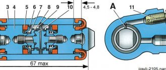
Vacuum unit structure of the VAZ 2110: 1 – vacuum amplifier housing; 2 – amplifier housing cup; 3 – rod; 4 – adjusting bolt; 5 – rod seal; 6 – sealing ring of the master cylinder flange; 7 – diaphragm return spring; 8 – amplifier stud; 9 – tip mounting flange; 10 – valve; 11 – hose tip; 12 – diaphragm; 13 – amplifier housing cover; 14 – sealing cover; 15 – piston; 16 – protective cover of the valve body; 17 – air filter; 18 – pusher; 19 – pusher return spring; 20 – valve spring; 21 – valve; 22 – valve body bushing; 23 – rod buffer; 24 – valve body; A – vacuum chamber; B – atmospheric chamber; C, D – channels.
Brake pressure regulator drive VAZ 2110
Drive device for the VAZ 2110 brake regulator: 1 – pressure regulator; 2, 16 – pressure regulator mounting bolts; 3 – pressure regulator drive lever bracket; 4 – pin; 5 – pressure regulator drive lever; 6 – axis of the pressure regulator drive lever; 7 – lever spring; 8 – body bracket; 9 – mounting bracket for the pressure regulator; 10 – elastic lever for the pressure regulator drive; 11 – earring; 12 – earring bracket; 13 – washer; 14 – retaining ring; 15 – bracket pin; A, B, C – holes.
Pressure regulator VAZ 2110
Diagram of the brake pressure regulator VAZ 2110: 1 – pressure regulator housing; 2 – piston; 3 – protective cap; 4, 8 – retaining rings; 5 – piston sleeve; 6 – piston spring; 7 – body bushing; 9, 22 – support washers; 10 – sealing rings of the pusher; 11 – support plate; 12 – pusher bushing spring; 13 – valve seat sealing ring; 14 – valve seat; 15 – sealing gasket; 16 – plug; 17 – valve spring; 18 – valve; 19 – pusher bushing; 20 – pusher; 21 – piston head seal; 23 – piston rod seal; 24 – plug; A, D – chambers connected to the main cylinder; B, C – chambers connected to the wheel cylinders of the rear brakes; K, M, N – gaps.
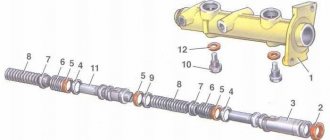
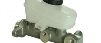
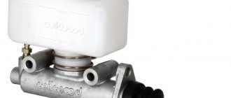
Main brake cylinder VAZ 2110
The structure of the main brake cylinder of the VAZ 2110: 1 – main cylinder body; 2 – low pressure sealing ring; 3 – drive piston of the “left front–right rear brake” circuit; 4 – spacer ring; 5 – high pressure sealing ring; 6 – pressure spring of the sealing ring; 7 – spring plate; 8 – piston return spring; 9 – washer; 10 – locking screw; 11 – drive piston of the “right front–left rear brake” circuit; 12 – connecting sleeve; 13 – tank; 14 – brake fluid emergency level sensor; A – gap.
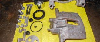
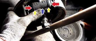
Brake mechanism of the front wheel of a VAZ 2110
The design of the front brake mechanism of the VAZ 2110: 1 – brake disc; 2 – pad guide; 3 – caliper; 4 – brake pads; 5 – cylinder; 6 – piston; 7 – pad wear indicator; 8 – sealing ring; 9 – protective cover of the guide pin; 10 – guide pin; 11 – protective casing.
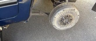
Brake mechanism of VAZ 2110 rear wheel
Diagram of the rear brakes of the VAZ 2110: 1 – hub fastening nut; 2 – wheel hub; 3 – lower tension spring of the pads; 4 – brake pad; 5 – guide spring; 6 – wheel cylinder; 7 – upper tension spring; 8 – expansion bar; 9 – finger of the parking brake drive lever; 10 – parking brake drive lever; 11 – brake mechanism shield.
VAZ 2110 rear brake wheel cylinder device
Diagram of the rear brake cylinder of the VAZ 2110: 1 – pad stop; 2 – protective cap; 3 – cylinder body; 4 – piston; 5 – seal; 6 – support plate; 7 – spring; 8 – crackers; 9 – thrust ring; 10 – thrust screw; 11 – fitting; A – slot on the thrust ring.
Handbrake drive VAZ 2110
Handbrake device VAZ 2110: 1 – lever fixation button; 2 – parking brake drive lever; 3 – protective cover; 4 – traction; 5 – cable equalizer; 6 – adjusting nut; 7 – lock nut; 8 – cable; 9 – cable sheath.
Brake fluid level sensor VAZ 2110
Design of the brake fluid reservoir cap of the VAZ 2110 with a level sensor: 1 – protective cap; 2 – sensor housing; 3 – sensor base; 4 – sealing ring; 5 – clamping ring; 6 – reflector; 7 – pusher; 8 – bushing; 9 – float; 10 – fixed contacts; 11 – moving contact.
Braking system design
The most important component of the VAZ 2110 brake system circuit is a vacuum booster and a dual-circuit regulator. The latter is responsible for creating pressure in the rear brake devices.
The brake drive is equipped with a piping system, which is divided into two circuits, brake devices and hoses. They allow the front and rear wheels to brake.
To activate the braking system, a special pedal is located inside the passenger compartment at the driver’s feet. In the VAZ 2110 car it is located in the middle. The main elements of the hydraulic drive are:
- Vacuum booster. Its design helps create pressure directed towards the master cylinder piston. This creates a braking effect.
- Pressure regulator drive. Through it, the brake fluid is directed to the rear devices of the braking system.
- Directly the brake pressure regulator of the VAZ 2110. Its function is to be responsible for the pressure force. The unit reduces or increases this indicator, depending on the load on the rear axle of the car.
- Master cylinder with reservoir and pistons. On the filler neck of this tank there is a sensor that monitors the emergency level of brake fluid.
- Front wheel brake mechanism. Its design includes cylinders, pads and a disc, plus a special alarm that warns of wear or malfunction of the lining.
- Rear wheel brake mechanism. Here the system is not disk, but drum. At least, this is the design the factory envisages. Some VAZ 2110 owners believe that drum mechanisms are not reliable and efficient enough, and therefore install disk devices in their place.
Disassembly
To replace and repair a damaged master brake cylinder, you need to remove it from the VAZ 2110; to do this, you should carry out several steps:
- Carefully disconnect all pipelines from a part such as the main cylinder;
- Disconnect the block equipped with wires from the emergency brake fluid indicator. They are connected by terminals;
- It is necessary to prevent fluid leakage and contamination of the mechanism; to do this, it is necessary to cover the openings of the unit and pipelines;
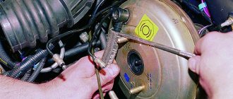
- Next, you need to remove it along with the tank; to do this, unscrew the fastening nuts that secure it to the vacuum type amplifier;
- After the VAZ 2110 fluid level sensor is removed, you need to drain all the brake fluid from the cylinder and basque;
We can only add to this that if there is no great need, you should not remove the reservoir from the master cylinder. To completely disassemble it, you need to remove the tank. Assemble and then install in place in exactly the reverse order.
Before you begin assembling the unit, all components must be washed with purified brake fluid or isopropyl alcohol. After this, everything must be carefully dried using a compressor, and then each of them must be wiped with a dry, clean cloth.
The main thing is not to get mineral oils directly or indirectly on the components; it is also dangerous for the front components of the main type brake cylinder, kerosene and diesel fuel to get on them.
If you find that the brake pedal has increased travel, it is recommended to bleed the brakes. The intricacies of the procedure can be found in this article: https://vazweb.ru/desyatka/tormoza/kak-prokachat-tormoza.html
How to remove and install the main brake cylinder on a VAZ 2110
Withdrawal procedure
1. Disconnect the negative cable from the battery.
2. Remove the soundproofing upholstery.
3. Disconnect the electrical connector from the brake fluid level sensor.4. Loosen the tightening of the nuts securing the 4 brake pipes.5. We unscrew the 2 nuts securing the main brake cylinder in the vacuum booster and remove it from the studs. Finally unscrew the nuts securing the brake pipes. In this case, a small amount of brake fluid may leak from the cylinder.
6. Drain the brake fluid from the reservoir by turning the cylinder upside down.
7. If your new cylinder does not have a reservoir, then you need to remove the reservoir from the old cylinder and remove the 2 rubber bushings on which it is attached. Worn bushings need to be replaced. We put these bushings on the new cylinder.
8. Place the master cylinder in place and tighten the nuts securing it. Pour brake fluid into the reservoir. Place a container or rag under the master cylinder to collect the fluid.
9. On the master cylinder, close the holes for the brake pipes with your fingers. Have an assistant slowly press the brake pedal until brake fluid flows out of the front master cylinder holes.
10. After this, you need to connect the tubes to the front holes of the cylinder and tighten the nuts that secure them. The pedal must be pressed. In the same way we connect the tubes to the rear holes of the cylinder. We install all removed parts in the reverse order. Check the brake pedal. If it is soft, then bleed the brake system.
Nuances of repair
O-rings require special attention. The time the rings are in isopropyl alcohol should not exceed twenty seconds, after which they should be dried immediately using a compressor.
The surfaces of the mirror, as well as the piston elements, must be completely clean and free of rust. Every disassembly and repair of a faulty brake master cylinder must be accompanied by replacement of the O-rings, even if they are in good condition. The cuffs of the device also require attention; if they are swollen and frayed, they must be replaced.
Brake hoses are used to supply brake fluid from the master cylinder. If there are cracks or abrasions, they must be replaced. Details: https://vazweb.ru/desyatka/tormoza/zamena-tormoznyh-shlangov.html
After all, it is necessary to check the elasticity of the piston springs; this should be done under load. The length of the spring under load should be 39.01–45.9 N (3.8–4.8 kgf) - 41 mm, with another option the following indicators should be 82.01–99.48 N (8.35–10 .15 kgf) – 21 mm. When free, the spring should have a length of 59.8 mm. If the springs do not have such indicators, then they must be replaced.
Required Tools
If you plan to do the repair yourself, then you need to check the availability of the following tools and materials:
- Screwdriver Set.
- Brake fluid.
- Special wrench for disassembling brakes “10”.
- Socket wrench “17”.
- Plug fittings.
- Pliers.
- Rubber caps.
- A set of keys.
- Socket wrench "13".
Advice! If in the VAZ 2110 mechanism, in addition to the sealing rings, other parts are damaged, then only replacing the GTZ will help. If the remaining elements are fully operational, you need to buy new rings and install them in place of the damaged parts.
Brake system VAZ 2110 - diagram
For better or worse, all Tolyatti models suffer from the same diseases. The perestroika virus brought them to the plant back in the 80s, along with the VAZ 2108, and since the genetics of the cars did not change, the diseases were the same. The VAZ 2110 is no exception. A nice replacement for the eights and nines appeared on the assembly line about 20 years ago, almost completely repeating the design of the front-wheel drive VAZ first-borns. The same applies to the brake system of the tenth family, which we will wash the bones with today.
Content:
2110 brake design
A dual-circuit hydraulic system with a vacuum brake booster is not uncommon on cars developed in the 80s. Easy to maintain, without unnecessary electronic bells and whistles, like ABS, cheap spare parts and pads. The front brakes are disc, and on models 2112, in the hatchback body, they are also ventilated with a larger diameter. This is because on the twelfth only 16-valve engines were installed and more effective brakes were needed to stop this incredible hundred-horsepower power. And also in order to cope with the Opel engine of 150 horsepower, which was also sometimes used for modification by dozens.
The rear brakes are tens of drum type, and the parking brake is mechanical. Everything is like in the good old classics. The car has a vacuum brake booster and the system is divided into two circuits. If one of them fails, the second one remains operational, so there won’t be a dozen left without brakes. The circuits work in a diagonal pattern - front-rear wheel diagonally. Also, the brake system of the VAZ 2110, the diagram of which is presented above, has a pressure regulator for uniform distribution of braking force, depending on the load of the rear axle. Both brake circuits are connected through the regulator.
Principle of operation
Hydraulic dual-circuit brakes with diagonal distribution are predominantly efficient and reliable. This is due to the fact that if one circuit fails, the second will allow your car to brake.
The circuit system is arranged as follows - one of them is responsible for the left rear and right front wheel, and the second circuit is responsible for the left front and right rear wheel.
This way, you will be able to brake without damaging the brakes or causing other problems with the system.
Malfunctions of the brake system of the VAZ 2110
The main malfunctions of the brake system of the VAZ 2110 can safely include the following set:
- brake fluid leakage through brake hoses;
- the brake pedal falls off;
- airing of the line due to a violation of the tightness of the connections or a fall
- brake fluid level in the reservoir;
- overheating of the front brakes, as a result of which the brake discs fail;
- malfunction of the vacuum brake booster.
There are not many malfunctions, but they do not bring joy. Most often, all fluid leaks occur due to the fact that the brake hoses of the front calipers are worn out. Whenever possible, they should be monitored from time to time. It is also common for the brake pedal to fail due to a defect or wear of the brake booster diaphragm. It is easy to identify such a breakdown. When the engine is off, the pedal will have normal travel, but it will be stiff. And when you start the engine, the pedal slowly goes to the floor. It should be taken into account that the depressed pedal moves 5-10 mm when starting the engine is a normal phenomenon on all VAZ cars with a vacuum booster. If the pedal fails, then you can safely make a claim against the amplifier’s diaphragm membrane. Most likely it is broken or simply worn out.
Device
Hydraulic brakes are installed on the machine and operate generally reliably. They are double-circuit and have a diagonal distribution. That is, if one part suddenly fails, then braking by another circuit is possible. For the sake of safety, the VAZ 2110 brakes operate diagonally, one circuit is the right front and left rear wheels, the other is also diagonal.
This device allows you to brake efficiently (without skidding and other troubles) even in the event of a malfunction, if the brakes in one of the circuits are lost.
Let's consider the design of the brake system. The hydraulic drive includes a vacuum booster, as well as a dual-circuit regulator that creates pressure in the rear brakes.
In addition, the hydraulic drive is equipped with pipelines divided into two circuits, hoses and brake mechanisms that provide braking to the front and rear mechanisms.
The hydraulic drive is activated by a pedal located in the cabin (middle). Here are the main components of the hydraulic drive:
- Vacuum booster.
It is designed in such a way that it creates pressure on the master cylinder piston, and thus causes braking; Vacuum brake booster - Pressure regulator drive.
It is through it that the working brake fluid flows to the rear brake mechanisms; Brake pressure regulator drive - The pressure regulator itself.
Already from the name it is clear that this device is responsible for the force of pressure, its decrease or increase. He does this depending on how loaded the rear axle of the car is; Pressure regulator - Main cylinder with pistons, equipped with a reservoir.
The filler neck of the tank is equipped with an emergency fuel level sensor; Master brake cylinder - Brake mechanism for the front wheel.
Its main parts are the disc, pads and wheel cylinders. The mechanism also provides an indicator to prevent complete wear and malfunction of the linings; Front wheel brake - Brake mechanism for the rear wheel.
Unlike the front disc brakes, the rear ones are drum brakes. This is the factory configuration. However, many car owners believe that their device does not provide high-quality braking, and change them to disc ones. Rear wheel brake
The brakes require attention. Without waiting for the warning light to come on, indicating a critical level of fuel fluid or wear of the linings, and even more so, without allowing the brakes to completely disappear, you need to carry out preventive checks.
Particular attention should be paid to all connections and hoses, since the “escaped” brake fluid will not make it possible to brake, and from here it’s not far from tragedy.
Repair of the brake system of VAZ 2110
Most often, repair and maintenance of brakes of the tenth family occurs during planned replacements of consumables - pads, brake discs, cuffs and seals. In this case, it is necessary to evaluate the degree of wear not only of the brake pads themselves, but also of the discs and drums. Often, no attention is paid to their condition until the pads literally begin to whistle. The normal service life of brake pads is up to 60 thousand, depending on the degree of hardness. But if the disc is worn out, the pad wears out much faster. Before changing pads, it is imperative to check the condition of the discs and drums, and, if necessary, sharpen or grind their surface.
Alarm Signals
The following symptoms are quite unsafe, please note:
- If the brakes are completely gone, then it’s clear that you can’t go any further, even to a service station! If independent repairs on site are beyond your capabilities, or simply impossible, you need to call a tow truck;
- When braking there is a strong vibration, especially felt in the steering column. You press the pedal, and it’s just hard to hold the steering wheel in your hands. There can be several reasons for vibration: • Many argue that vibration can occur due to the fact that there are non-ventilated disks. Their design is such that they really don’t like it when braking occurs in the rain, or even right in a puddle. No repair will help here - you need to replace the disks with ventilated ones; • Vibration may also occur if there is a problem with the rear drums. If upon inspection you find dark spots on the working surface, this indicates uneven wear. The vibration is usually very strong. Such drums need urgent repairs, and possibly replacement with disc brakes; • Check the front brake discs for deformation. At the same time, vibration is also observed.
- The brake pedal is too tight. There may also be several reasons for this: • A clogged air filter for the vacuum booster can cause the pedal to become stiff; • Check the vacuum booster itself. Its possible malfunctions are destruction of the diaphragm, tip, sticking of the check valve, damage to the hose connecting the intake manifold to the amplifier. In all these cases, a stiff pedal syndrome may occur, and repair of any of the indicated faults is necessary; • Also, the pedal may become stiffer as the pads wear, check them too.
- Hisses when you press the brake. If it hisses exactly when you press the pedal, you need to urgently check the vacuum booster, and then decide whether it needs repair or replacement. But if it hisses when you release the brake, then this is a normal phenomenon. Unless, of course, the hiss is too obvious.
Bleeding the brake system of a VAZ 2110
Bleeding the car's brake system is necessary to remove air from the line. Air locks can appear not only due to a drop in the level of brake fluid in the reservoir, but even without any apparent reason for the leak. This can happen due to overheating of the brakes, when the brake fluid boils, and air bubbles released from the fluid during boiling accumulate and form an impressive plug that requires removal. Then the brakes need to be bled. This is done according to a certain algorithm:
- Liquid is added to the tank to the top mark, the lid does not close.
- We start pumping from the wheel farthest from the main brake cylinder.
- An assistant pumps the brake pedal to the highest possible position.
- A hose is put on the fitting, the second end of which is lowered into a container with brake fluid.
- The fitting on the wheel cylinder unscrews, the liquid comes out along with the air, the pedal falls and rests on the floor.
- The fitting is tightened, the pedal is inflated again, the operation is repeated for each of the wheels, while you need to add fluid to the tank and make sure that during pumping its level does not fall below the control mark. If necessary, the procedure is repeated.
In this way, the functionality of the brake system of the VAZ 2110 is restored. In order to avoid problems with the dozens of brakes, it is enough to check the level of brake fluid in the reservoir from time to time and monitor the condition of the brake wheel mechanisms. Then the brakes will be reliable, the ride will be safe, and the driving experience will be the most positive. Watch your brakes and good luck on the road!
Brake system
Hydraulic brake circuit diagram
If one of the circuits of the service brake system fails, the second circuit is used to stop the vehicle with sufficient efficiency.
The hydraulic drive includes a vacuum booster 6
and a dual-circuit rear brake pressure regulator
9
.
The parking brake system is driven by the brake mechanisms of the rear wheels.
Frame 24
plastic valve.
At the exit from the lid it is sealed with a corrugated protective cover 16
.
The valve body contains the
main cylinder drive
3 23
,
valve body
15
assembly
21
pusher and valve
19
and
20 17
, pusher
18
.
When you press the pedal, the pusher moves 18
, piston
15
, and after them valve
21
until it stops against the seat of the valve body.
In this case, cameras A
and
B
are separated.
As the piston moves further, its seat moves away from the valve and through the resulting gap, chamber B
is connected to the atmosphere.
The air entering through filter 17
, the gap between the piston and the valve and channel
D
creates pressure on the diaphragm
12
.
Due to the difference in pressure in chambers A
and
B,
the valve body moves together with the rod
3
, which acts on the piston of the main cylinder.
When the pedal is released, the valve 21
moves away from the housing seat and through the resulting gap and channel
C
of chambers
A
and
B
communicate with each other.
Pressure regulator drive
Pressure regulator 1
(Figure Pressure regulator drive) is attached to bracket
9
with two bolts
2
and
16
.
In this case, the front bolt 2
simultaneously secures the fork bracket
3
of the lever
5
of the pressure regulator drive.
A two-arm lever
5
on the pin of this bracket with a pin 4 .
Its upper arm is connected to an elastic lever 10
is pivotally connected to the rear suspension arm bracket through an earring
11
bracket 3
Together with lever
5
, due to the oval holes for the fastening bolt, it can be moved relative to the pressure regulator.
This regulates the force with which lever 5
acts on the regulator piston (see here).
The regulator has four chambers: A
and
D
(Figure Pressure regulator) are connected to the main cylinder,
B
– to the left, and
C
– to the right wheel cylinders of the rear brakes.
In the initial position of the brake pedal, the piston 2
(see figure Pressure regulator) is pressed by lever
5
(see figure Pressure regulator drive) through the leaf spring
7
to the pusher
20
(see figure Pressure regulator), which under this force is pressed against the seat
14
of the valve
18
.
In this case, valve 18
is pressed away from the seat and a gap
H
, as well as a gap
K
between the piston head and seal
21
.
Through these gaps, chambers
A and
D
communicate
with chambers
B
and
C.
When you press the brake pedal, fluid flows through the gaps K
and
H
and chambers
B
and
C
enter the wheel cylinders of the brake mechanisms.
As the fluid pressure increases, the force on the piston increases, tending to push it out of the housing. When the force from the liquid pressure exceeds the force from the elastic lever, the piston begins to move out of the body, and after it, the
pusher
20
12
and
17 along with the sleeve
19
and rings
10
.
In this case, the gap M
increases, and the gaps
H
and
K
decrease.
When the gap H
is completely selected and valve
18
isolates chamber
D
from chamber
C
, pusher
20
, together with the parts located on it, stops moving after the piston.
Now the pressure in chamber C
will change depending on the pressure in
chamber
B. With a further increase in the force on the brake pedal, the pressure in chambers D
,
B
and
A
increases, piston
2
continues to move out of the body, and sleeve
19
, together with o-rings
10
and plate
11
,
moves towards plug
16 under increasing pressure in chamber
B. In this case, the gap M
begins to decrease.
By reducing the volume of chamber C
, the pressure in it, and therefore in the brake drive, increases and will be practically equal to the pressure in
chamber
B. When the gap K
becomes zero, the pressure in chamber
B
, and therefore in chamber
C
will increase to a lesser extent than the pressure in chamber A due to throttling of the liquid between the piston head and seal
21
.
The relationship between the pressure in chambers B
and
A
is determined by the ratio of the difference in the areas of the head and piston rod to the area of the head.
When the vehicle load increases, the elastic lever 10
(see figure Pressure regulator drive) is loaded more and the force from lever
5
on the piston increases, that is, the moment of contact between the piston head and seal
21
(see figure Pressure regulator) is achieved at higher pressure in the main brake cylinder. Thus, the effectiveness of the rear brakes increases with increasing load.
If the brake circuit “left front - right rear brake” fails, the O-rings 10
, the sleeve
19
, under the pressure of the liquid in chamber
B
, will move towards the plug
16
until the plate
11
in the seat
14
.
The pressure in the rear brake will be regulated by a part of the regulator, which includes a piston 2
with a seal
21
and a sleeve
7
. The operation of this part of the regulator, in the event of a failure of the said circuit, is similar to operation with a working system. The nature of the change in pressure at the outlet of the regulator is the same as with a working system.
If the brake circuit "right front - left rear brake" fails, the brake fluid pressure pusher 20
with sleeve
19
, sealing rings
10
moves towards the piston, pushing it out of the body.
M
gap increases and the
H
decreases.
When valve 18
touches seat
14
, the increase in pressure in chamber
C
stops, that is, the regulator in this case works as a pressure limiter. However, the achieved pressure is sufficient for reliable operation of the rear brake.
In the building 1
a hole is made, closed with a plug
24
.
Liquid leakage from under the plug when it is squeezed out indicates leakage of the rings 10
.
Master brake cylinder with reservoir
Why do you need a pressure regulator?
Not every owner of a domestic “ten” will understand why the brake pressure regulator on a VAZ 2110 needs to be replaced. Simply, this name is not familiar to everyone. A popular designation for a regulator is a sorcerer.
This very sorcerer is located on the rear suspension of your car. It has a lever with a movable position. Depending on the moment of load on the spring, its position changes.
The voltage generated during actuation is directed and distributed to the brake piston. Pressing the piston pedal reduces the load on the rear pads. If the brake system is working properly, the loads are distributed evenly.
In order for the unit to function efficiently and without errors, it is necessary to adjust the brake pressure regulator on your VAZ 2110. This way you can prevent untimely wheel locking.
GTZ VAZ 2110 signs of malfunction, purpose of the device, performance check replacement
Despite the fact that these two units are inextricably linked with each other, in our material we will consider them separately. This will allow you to understand in detail all the nuances and features of the operation and repair of the two devices.
I – main cylinder body; 2 – low pressure sealing ring; 3 – drive piston of the “left front-right rear brake” circuit; 4 – spacer ring; 5 – high pressure sealing ring; 6 – pressure spring of the sealing ring;
7 – spring plate; 8 – piston return spring; 9 – washer; 10 – locking screw;
II – drive piston of the “right front-left rear brake” circuit; 12 – connecting sleeve; 13 – tank; 14 – brake fluid emergency level sensor; A – gap
Vacuum booster
The braking system of a car certainly cannot be called perfect, so it has to be supplemented with devices that help improve efficiency. One of them is a vacuum booster.
Application and purpose
Today, a vacuum amplifier is in great demand because it is highly efficient.
Its tasks are extensive, but the amplifier copes with them all perfectly:
- The degree of resistance of the brake pedal increases;
- Reduces the load on the brake system;
- Acts as a highly efficient auxiliary unit;
- Has a positive effect on the service life of the brake system, etc.
This element has the following components:
- Dense body, for the manufacture of which a high-strength polymer is used;
- The diaphragm, which is also called the collecting node;
- Monitoring or control specialized valve;
- Pusher. It allows you to return the engine elements to their original position when there is no power;
- Main piston rod of the brake system cylinder (main);
- Switch return spring.
The body of this spring has two cellular divisions, which are divided into vacuum and atmospheric. Cells are often called chambers.
- The vacuum chamber is a cell directly connected to the brake master cylinder.
- The atmospheric chamber is a cell located opposite the brake pedal. Its open part of the body rests on the brake pedal.
It is also worth noting the diaphragm, which performs two very important tasks:
- Corrects the position of the piston in space;
- Pumps brake fluid to the main brake cylinders.
Installing a vacuum booster involves a serious change in the sensitivity of the pedal, so it is strongly recommended not to apply a large and sudden force to it in the “first couple”. Pressing should be done carefully and smoothly.
Malfunctions and ways to check them
It is possible that you may need to replace the vacuum booster on your VAZ 2110. The cause may be various malfunctions, the characteristic symptoms of which are as follows:
- When you press the brake pedal, a hissing noise occurs, and at the same time, the engine speed often increases;
- The car starts to shake;
- Spark plugs stop working efficiently;
- Fuel consumption increases noticeably.
Before replacing the vacuum booster on a VAZ 2110, it should be checked.
This procedure is performed as follows:
- As with normal bleeding of brakes, with the engine not running, press the gas pedal several times;
- After 5 or 6 presses, keep the pedal in the down position, resting it on the floor, and start the engine;
- After starting, the pedal itself will move forward a little.
There is also a high probability of damage to the diaphragm, on which a hole is formed over time. You can purchase the diaphragm with a repair kit, the cost of which is no more than 500 rubles.
Replacement
To replace an element, you need to understand the main issue - how to remove the vacuum booster from a VAZ 2110. Directly replacing the old element with a new one will not be difficult, just like the reassembly process.
Therefore, we will tell you about the main thing - dismantling the amplifier. Let's start with the fact that the procedure is not complicated, but it requires accuracy and sequence of steps. If you follow the recommendations, the work will take little time and will not take much effort.
- Disconnect the block with wires, which includes brake fluid level sensors in its design.
- Hold the booster check valve with one hand and carefully disconnect the hose with the other. It is advisable to disconnect the hose with a strong hand, since this will require a lot of force.
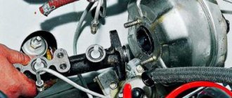
- Remove the two bolts connecting the booster and master cylinder.
- Carefully remove the cylinder from the amplifier.
- There is no point in disconnecting the brake lines.
- Give access to the dashboard, which will allow you to unscrew the nuts holding the brake pedal bracket. There should be 4 of them.
- It is recommended to dismantle the bracket and amplifier through the engine compartment, since there is enough free space for such manipulations.
- Remove the pin lock plate. To do this, pry the finger with a screwdriver and squeeze it out.
- Now you can easily disable the brake pedal and booster.
- To disconnect the amplifier and bracket, you will have to unscrew the two nuts on the mount.
- A new one is installed in place of the dismantled old vacuum amplifier, and the reassembly procedure is performed in strict sequence of the dismantling process.
Problems and their solutions
There are several common problems associated with brakes on a VAZ 2110 car. The reasons for their occurrence may be different, but the solution is always the same - timely and high-quality repairs.
- The brakes have completely lost their effectiveness, pressing the pedal does not cause any reaction. In such a situation, it is categorically impossible to drive anywhere under your own power, even if we are talking about a trip to a service station? How do you brake? About a wall or pillar? Call a tow truck and start repairs. In some situations, the problem can be solved on the spot, but these are temporary measures.
- During braking, strong vibrations are observed, most often in the steering column. At the same time, when you press the pedal, it is difficult to hold the steering wheel in your hands. There may be several reasons for this: If you have non-ventilated discs installed, similar situations may arise during rain or when braking through a puddle. Such devices do not like moisture, so to get rid of vibrations, replace the disks with ventilated ones;
- Another cause of vibrations is faulty drums. If there are dark spots on the working surface of the drums, the unit wears unevenly. Immediate repair or complete replacement of mechanisms is required;
- Be sure to check for signs of deformation on the front brake discs. They often cause vibrations.
- The vacuum booster air filter may be clogged, causing the brake pedal to feel stiff;
As you can see, the brake system of the VAZ 2110 car is far from perfect in its factory version, but it performs its functions effectively and reliably. All possible malfunctions can easily be fixed independently, but in some situations it is advisable to contact a professional service station.
Source
Master brake cylinder
Now let's talk about the master brake cylinder on a VAZ 2110 car. If you do not want to allow the brakes to fail while driving, they should be checked periodically, and if problems arise, take appropriate action immediately.
A common reason for replacing the master brake cylinder of a VAZ 2110 is precisely the fact that the brakes are lost.
Symptoms of a problem
Of course, brakes can completely lose their effectiveness for various reasons, but now we are talking specifically about the master cylinder. If the reason lies therein, then it can be determined by the following signs:
- The master cylinder shows signs of brake fluid leakage;
- The pedal has an idle motion, that is, when it is pressed, no force is created;
- The brake pedal simply won't press.
Replacement
The most difficult process is disassembly. Therefore, let's talk about it in more detail.
- Carefully disconnect the master cylinder from the pipeline.
- Disconnect the block, which is equipped with wiring, from the emergency brake fluid indicator. The connection to the “ten” is made by terminals.
- Cover the pipe and assembly openings with something to prevent brake fluid from leaking. It will pollute the interior space, which is undesirable.
- Now remove the cylinder along with the reservoir. To do this, simply unscrew the fastening nuts that connect the element to the vacuum booster.
- After removing the brake fluid level sensor, drain the brake fluid present from the cylinder and the cylinder itself.
- If there is no serious need, you should not remove the tank. But for complete assembly, the tank is removed and then installed in place in strict order.
- Before reassembly, each element is washed with purified brake fluid. A good alternative is isopropyl alcohol.
- Do not forget to dry the parts with a compressor and wipe with a clean, dry cloth.
- Carefully avoid contact of the main cylinder with fuel or kerosene.
- Pay special attention to the O-rings. If you wash them with special alcohol, do not keep the rings in this liquid for more than 20 seconds. After processing, immediately dry and wipe the seals.
- Treat the surface of the piston and mirror to remove all rust.
- When replacing the master cylinder, new O-rings must be installed, regardless of their current condition.
- Check the elasticity of the piston springs under load. Refer to the VAZ 2110 repair manual, which indicates the appropriate loads and forces for testing.
- When free, the length of the spring should be 59.8 millimeters. If the indicator deviates from the norm, be sure to replace the springs.
Leveling up
If you think that after replacing the brake master cylinder you can safely go out on the roads, then you are mistaken. In fact, a complete repair of brake cylinders on a VAZ 2110 includes bleeding.
The procedure is not complicated, but requires following the instructions:
- Find someone who will help you in this matter. One will be near the car, and the second will be directly in the cabin.
- Inflate the brake pedal by pressing it several times.
- The assistant presses the pedal, and meanwhile you slightly unscrew the fitting on one of the brake system pipes.
- This should release air, as well as a small amount of brake fluid. Don't be alarmed by leaks, this is completely normal.
- Retighten the fitting using the same wrench as when unscrewing - 10.
- Command your assistant to lower the part.
- The procedure is repeated until air bubbles begin to come out when unscrewing the fitting.
- Each of the four circuits is pumped using similar actions.
- First make sure that the brake fluid in the expansion tank is filled to the required level.
Actually, at this point the repair work related to the master brake cylinder can be considered complete. Experience in operating a car like the VAZ 2110 suggests that you should always store a container of brake fluid in the trunk. All sorts of situations happen on the road, and you need to be prepared for them.
If you find an error, please select a piece of text and press Ctrl+Enter.