A modern car is now equipped with a variety of active safety systems, the list of which is growing every year. These also include a system to prevent wheel locking during braking - ABS (Anti-lock braking system).
ABS is one of the very first safety systems that began to be used on a car, and it is now found on almost all cars, from budget categories to premium ones.
Let's briefly consider the purpose of ABS - this system is needed so that the wheels do not lock during braking, but continue to rotate, albeit at a slower rate.
Thanks to this, the grip of the wheel on the road surface is not lost and the likelihood of the car skidding is completely eliminated, the car remains fully controlled by the driver.
ABS has been used in vehicles for a long time and has proven its effectiveness more than once.
This system works simply. There is an electronic unit that controls the deceleration rate of each wheel. And if one of them stops faster than others, the block reduces the force of fluid pressure in the brake caliper on this particular wheel, that is, the brake mechanism begins to act less.
You can read more about the ABS device and other information on this system here.
What is the ABS sensor for?
It is stated above that the ABS unit, popularly called the “brains” of the braking system, controls the speed of rotation of the wheels, so the design of this system could not be done without sensors.
They are the “sense organs” of this system and based on their readings the ABS functions.
The first anti-lock braking system used only one sensor, which was installed in the axle of rear-wheel drive cars.
But as ABS has improved, their number has increased; modern cars already use 4 sensors. This allows the system to monitor the rotation speed of each wheel individually.
How to check the ABS sensor
Publication date: December 05, 2022. Category: Automotive equipment.
ABS (anti-lock braking system), consisting of an electronic control unit, a hydraulic unit, rear and front sensors, is designed to prevent the car's wheels from locking during emergency braking. Its main purpose is to maintain vehicle controllability and stability, as well as to help reduce braking distances. Therefore, it is so important that all sensors installed in the car are in good working order. To check them, it is not at all necessary to go to a car service center. You can deal with this problem yourself.
Types of sensors
There are three types of such elements, differing in their operating principle. The most common passive sensors are induction type.
The essence of their work comes down to a change in voltage due to the influence of a magnetic field. Their main disadvantage is the inability to determine the speed of rotation of the wheel at very low speeds.
The remaining two types are active.
One of them is magnetoresistive (rare). The principle of its operation is based on the magnetoresistive effect - the property of a semiconductor to change the trajectory of electrons when exposed to a magnetic field.
The second type of active sensor uses the Hall effect, in which electrons on a semiconductor wafer move to its edges when the magnetic field changes.
Basic malfunctions of the ABS system
Any driver who has ever had an ABS light come on in a Priora will tell you about the sensor. But it could be worse - if the ABS in Priora does not work. There are several options in which to look for the source of the problem:
- wiring damage;
- mechanical damage to the brake fluid pressure valve block;
- failure of speed sensors.
The first thing you need to do when you see the light (ABS lights up) is to read the error symbols using a special diagnostic scanner. Each item in the ECU is indicated by a corresponding code:
- C0040 – the speed sensor (DSC) of the right front wheel is faulty;
- C0035 – DSC of the left front wheel is faulty;
- C0050 – DSC of the rear right wheel is faulty;
- C0045 – DSC of the rear left wheel is faulty;
- C0065 – front left valve (intake);
- C0060 – front left valve (exhaust);
- C0075 – front right valve (intake);
- C0070 – front right valve (exhaust);
- C0085 – rear left valve (intake);
- C0080 – rear left valve (exhaust);
- C0095 – rear right valve (intake);
- C0090 – rear right valve (exhaust);
- C0161 – the braking signal does not turn off;
- C0121 – power to the valves does not turn on;
- C0110 – electric return pump.
- C0550 – error in the “brains” - ECU;
- C0245 – error in receiving data from sensors;
- C0800 – power surges.
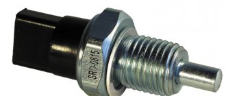
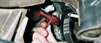
The solution may be simpler: an ABS sensor is installed under the fender liner. Dirt often gets into this area; an unprotected piece of wiring near the DSC connector can be damaged. Replacing it will help.
Sensor Features
There are several significant differences between passive and active types. They are called passive because they do not require voltage to operate; such a sensor itself generates electrical impulses, to which the electronic unit reacts. Active elements require voltage to be applied to them.
Passive elements are very simple in design and are very reliable. That's why they are so common, despite their shortcomings.
Active types of sensors use microcircuits in the design, which complicates the element and makes it more vulnerable. But they are highly accurate and do their job even at low speeds.
Since all types of sensors operate under the influence of a magnetic field, it alone is not enough in the design; another element is needed to which it would react.
The induction (passive) type uses a ferromagnetic alloy pulse gear ring mounted on the drive hub or shaft, as well as on the steering axle. Previously, it could also be mounted on the bevel gears of the main drive.
In active types, a magnetic pulse ring is used. In the case of a magnetoresistive sensor, this ring is divided into alternating sectors with permanent magnets of different polarities.
But the Hall sensor uses a regular magnetic ring, without any sectors, integrated into the wheel bearing.
ABS device on Priora
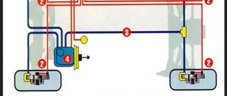
The main task of ABS is to prevent the wheels from locking during braking. To fulfill its task in Priora, the anti-lock braking system works like this:
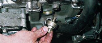
- At the moment of braking, the ECU receives data from ABS sensors that read the speed (they are located behind the hubs).
- The anti-lock braking system ECU is a unit with internal brake fluid pressure valves and an electric return pump. Its location is the front left side member.
- When the sensors transmit data about a sharp jump - instantaneous braking of the wheels - the fluid pressure is gradually released using valves.
- A malfunction of any system leads to the transmission of an error signal through the computer, which appears to the driver as a “burning ABS on the dashboard.”
Inductive type element design
Since inductive sensors are the most common, their design will be considered in the future.
Such a sensor consists of an inductive coil, inside of which a magnetic core is placed. It is installed next to the toothed impulse ring, but so that there is a certain gap between them.
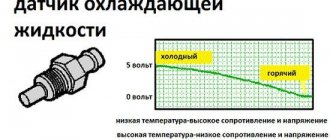
When the wheel rotates, the ring teeth pass through the magnetic field created by the core, which affects the magnetic flux, causing the alternating voltage value in the coil winding to change.
As a result, the speed of rotation of the wheel, and with it the pulse ring, affects the frequency and amplitude of oscillations of the output voltage on the coil. These parameters are fed to the “brains”, as a result of which they estimate the speed of deceleration of the wheel.
Problems with at least one of the ABS sensors can lead to a complete shutdown of the system. And although the braking system on the car will work, you can forget about the braking efficiency and safety that ABS provided.
Checklist: Priora abs sensor -18 system errors, removal and installation of the unit
The abs sensor of a Priora car is placed near the wheels. It comes in front and back. The ABS unit is placed near the engine on the right, if you open the hood and stand in front of the car. When AbS (ABC) lights up on the panel, it means there is a problem with the system. Why do cars need this system? Abs affects the braking of the car, Priora with this system brakes 2 times faster than without it. The wheels brake in small portions, measured by a computer. Initially in 2008 there were cars without it. Read the article to the end and find out what the error is, what it is responsible for and why the ABS lights up and does not work. Priora has sensors and an ABS unit. Failure of any spare part leads to problems. On the Prior, there are 18 errors belonging to the braking system.
The appearance of an icon on the dashboard indicates an error occurring in the operation of the vehicle. There are serious errors on the Priora, if they occur, you should not tempt fate and move on, but there are errors that can be postponed. For example, the ABS system is considered very valuable for a modern driver in a car.
The Priora's ABS system saves you during unexpected and sudden braking and makes the process itself more efficient, reducing the braking distance. Therefore, when the ABS light is on on the Priora’s dashboard, strange feelings of uncertainty arise - knowing that the road situation can be so unpredictable that you will have to brake sharply, you involuntarily have to look for the reason why the icon appeared on the dashboard.
As in many systems, this behavior of the car's control unit may result in the ABS sensor on the Priora having to be replaced. A large system with a fairly simple device is worth checking - for your own safety.
Causes of sensor malfunction
The induction sensor is characterized by its simple design and high reliability; malfunctions with it occur very rarely. The problem most often lies in the wiring through which signals are sent to the control unit.
Since the sensors and their wiring are located directly next to the wheels, over time the circuit may break or short out. Often, sensor failures occur due to oxidation of the contacts.
Due to the fact that after turning on the ignition on a car, ABS always undergoes self-diagnosis, during which the condition of all elements of the system is assessed, it is quite simple to identify problems with the sensors; if they occur, the warning light will constantly light up on the dashboard.
In total, there are 4 types of system behavior when a malfunction is detected:
- Self-diagnosis detects an error and ABS is disabled. This may be a sign of an error in the control unit, or a break in the wiring coming from the sensor;
- The system undergoes diagnostics, during which no problems are detected, but after this the ABS is turned off. This result usually results from problems with the wiring going to the sensors (oxidation, open circuit, short circuit, etc.);
- Self-diagnosis detects an error, but the system does not turn off and continues to operate. This usually indicates a break in the wiring on one of the sensors;
- ABS does not turn on. This can happen due to a broken wiring, or because the impulse ring is damaged, chipped or broken. This result can also be produced by a heavily worn hub bearing, which is why there is significant play in it.
Since malfunction of ABS often occurs due to wiring, it is quite simple to identify a faulty element and all you need is a multimeter.
Of course, it is better to check using an oscilloscope, since such a device makes it possible to visually assess the amplitude and frequency of voltage fluctuations in the sensor, but not everyone has one.
Next, we’ll figure out how to check the ABS sensor on different cars, although in general the procedure is the same, despite the fact that any type of sensor can be used on different models.
How to diagnose the ABS system
To obtain complete and reliable information about the state of the entire system, diagnostics should be carried out using special equipment. For this purpose, the manufacturer provides a special connector. After connection, the ignition is turned on and the test begins. The adapter issues error codes, each of which signals a breakdown of a specific component or element of the system.
A good model of such a device is Scan Tool Pro Black Edition from Korean manufacturers. The 32-bit chip makes it possible to diagnose not only the engine, but also all components and assemblies of the car. The cost of such a device is relatively low.
Diagnostics can also be carried out at service centers and service stations. However, even in garage conditions, if you have certain knowledge, identifying defects will not be difficult. To do this, you will need the following set of tools: soldering iron, tester, heat shrink and repair connectors.
The check is performed in the following sequence:
- the wheel being tested is jacked up;
- the control unit and controller outputs are dismantled;
- repair connectors are connected to the sensors;
- The resistance is measured with a multimeter.
A fully functional ABS sensor at rest has a resistance of 1 kOhm. When the wheel rotates, the readings should change; if this does not happen, the sensor is faulty. It should be remembered that different sensors have different meanings, so you need to study them before starting work.
Checking the ABS sensor with a multimeter
In addition to the device itself, you need to find a description of the sensor model. Further work is performed in the following sequence:
- The machine is placed on a flat, uniform surface, and its position is then recorded.
- The wheel is removed where the ABS sensor will be checked.
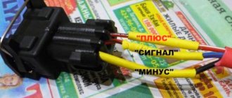
- The connector is disconnected and the contacts of both the sensor and the plug itself are cleaned.
- The wires and their connections are inspected for abrasions and other signs of damage to the insulation.
- The multimeter switch is switched to resistance measurement mode.
- The tester probes are applied to the output contacts of the sensor and readings are taken. Under normal conditions, the device display should show the number indicated in the sensor data sheet. If there is no such information, we take readings of 0.5 - 2 kOhm as the norm.
- Then, without removing the probes, the car wheel spins. If the sensor is working properly, the resistance will change, and the higher the rotation speed, the more the resistance changes.
- The multimeter is switched to voltage measurement mode and measurements are taken.
- At a wheel rotation speed of 1 revolution/sec. The indicator should be within 0.25 - 0.5 V. The higher the rotation speed, the greater the voltage.
- All sensors are checked in the same sequence.
In addition, the entire wiring harness is connected to each other to make sure there is no short circuit.
It should be remembered that the design and values of the sensors on the rear and front axles are different.
Based on the data obtained during measurements, the performance of the sensor is determined:
- the indicator is lower than normal - the sensor is unusable;
- a very low resistance value or near zero - short circuit of the coil turns;
- when bending the wiring harness, the resistance indicator changes - the wire strands are damaged;
- the resistance indicator tends to infinity - a break in the conductor or core in the induction coil.
You should know that if, during diagnostics, the resistance reading of one of the ABS sensors is very different from the others, it means it is faulty.
Before you start ringing the wires in the harness, you should find out the pinout of the control module plug. Then the connections between the sensors and the ECU are disconnected. And after that, you can start sequentially ringing the wires in the harness according to the pinout.
Checking the ABS sensor with an oscilloscope
An oscilloscope can also be used to determine the performance of ABS sensors. However, it is worth noting that this will require some experience in working with it. If you are one of the avid radio amateurs, then this will not seem difficult, but the average person may have a number of difficulties. And the main one is the cost of the device.
This device is more suitable for specialists and craftsmen of service centers and service stations. However, if you have such a device, it will be a good assistant and will help identify faults not only in the ABS system.
An oscilloscope is used to visualize the electrical signal. The amplitude and frequency of the current are displayed on a special screen, thanks to this you can obtain accurate information about the operation of a particular element.
So, the test begins using the same method as with a multimeter. Only at the multimeter connection point is an oscilloscope connected. And then the sequence is like this:
- the suspended wheel rotates at a frequency of approximately 2 - 3 revolutions per second;
- vibration readings are recorded on the instrument display.
After determining the integrity of one wheel, you should immediately begin checking on the opposite side of the axle. Afterwards, the data obtained is compared and conclusions are drawn based on them:
- provided that the readings are relatively identical, the sensors are in good working order;
- the absence of a step-like phenomenon when setting a smaller sinusoid signal indicates normal operation of the sensor;
- a stable amplitude with peak values not exceeding 0.5 V at the speeds mentioned above indicates the integrity of the sensor.
Checking without instruments
The performance of ABS sensors can also be checked by the presence of a magnetic field. To do this, take any iron object and apply it to the sensor body. When the ignition is turned on, it should be attracted.
In addition, you should carefully inspect the sensor itself and its installation location for damage. The wire should not have any abrasions, chips, insulation damage, etc. The sensor connector must be free of traces of oxidation.
It is important to know that the presence of dirt and oxidation can distort the signal from the sensor.
Check on Ford Focus 2
First, let's look at how the test is carried out on a Ford Focus 2. This car uses a Hall effect sensor and is located in the upper part of the wheel hub. It is easy to detect - just remove the wheel, unscrew and move the caliper to the side, and also remove the brake disc.
Before starting the inspection, be sure to check the tire pressure. It must be the same in all wheels, otherwise the pressure difference may affect the performance of the system.
To check the sensor on Focus 2, for ease of access, you should jack up and remove the wheel from the side being tested.
Next, disconnect the block of wires coming from the sensor. We visually assess the condition of the braid and wires; they should not show abrasions or other types of damage.
At the first stage, we check the resistance. To do this, switch the multimeter to ohmmeter mode and connect its probes to the terminals in the block.
On Focus 2, the sensor resistance when measured should be in the region of 1.3-1.4 kOhm.
But there is one nuance that is important to consider. During measurements, you should knead the wire, especially at bends.
The fact is that at the point where the wire is broken, the copper conductors can come into contact, and therefore the sensor can show normal resistance. And during crumpling and bending, contact is broken.
If the readings do not match, a measurement should be taken at the input of the wires to the sensor. This will reveal whether the problem lies in the sensor itself, or just in the wires.
If, when checking the resistance near the element, a discrepancy in resistance remains, then the sensor must be replaced.
In some cases, the cause of the problems lies in contamination of the semiconductor platinum of the Hall element. Therefore, you should remove the sensor itself and clean it.
In addition to the sensor wiring, you should also check the entire circuit for damage. To do this, you need to disconnect the wire block from the control unit.
Then we find out from the technical documentation for the car which terminals on the block correspond to which sensor, after which we connect a multimeter to the necessary connectors and measure the resistance.
If it does not meet the required parameters, you should look for a break in the area from the control unit to the sensor connection block.
Faults such as breaks or short circuits can be treated by replacing the wires. But if the element itself malfunctions, it is replaced.
Using a laptop as an oscilloscope
From a technical point of view, professionals consider using an oscilloscope to be the most correct method for checking ABS sensors. However, the device is expensive, and it makes no sense to purchase it just to test sensors. Well, if you have a laptop, then using it as an oscilloscope is quite simple. First, we make a measuring cord to connect the sensor connector to the microphone input. To do this, you will need a 3.5 mm mini jack plug, two resistors and a couple of pieces of wire of a suitable length. The cash costs for purchasing the necessary components will not exceed 50 rubles. We solder the wires to the contacts of the mini-jack, and install a resistive divider in the gap (to protect the sound card) according to the diagram below.
Then everything is simple:
- We install a special Oscilloscope program on the laptop (for example, Winscope or Avangard).
- We connect the wires to the ABS sensor connector, and the plug to the microphone input.
- Rotate the wheel hub.
- If the sensor is working properly, we see a clear sinusoidal signal on the screen.
On a note! If you don't have an assistant, it will be very difficult to rotate the wheel and watch the laptop screen at the same time. For convenience, we recommend using the recording function. By turning on the playback mode (after performing the test described above), you will be able to see the test results.
Diagnostic features for BMW E39
Next, let's look at the nuances of checking the ABS sensor on a BMW E39. This car already uses an induction element.
Diagnostics are carried out using the same methods as for Focus 2. That is, the resistance of the sensor, its wiring, as well as the circuit from the control unit are checked.
Since this car uses an induction type element, it is additionally possible to measure the output voltage.
To do this, switch the multimeter to voltmeter mode and connect it to the sensor wiring connectors.
Next, spin the wheel to approximately 50 rpm. In this case, the element being diagnosed will begin to generate electricity, the voltage of which should be around 2 V.
Standard sensor and ABS unit - article number and price
The anti-lock braking system operates the rear and front wheels. It contains several brackets, brackets, and other fasteners that ensure accurate operation of the ABS and hydraulic unit damper (article 11180353832400, price - about 30 rubles). But only three items are considered the main ones in ABS:
ABS control unit (“brain”) - article number 11180353801001, cost - about 10,000 rubles; Front wheel speed sensor - catalog number 11180353835000, cost - about 1,000 rubles; Rear wheel sensor - catalog number 11180353837000, cost - 1000-1200 rubles. Often, to solve the problem, you only need to buy an anti-lock sensor from Priora, so the scale of financial costs is not as huge as it seems at first.
Design nuances of Lada "Priora", "Kalina"
Now let’s figure out a little how to diagnose and replace Lada cars of the Priora and Kalina models. These cars were taken as an example because they use drum brakes at the rear, and above we looked at how work is carried out with sensors that work with disc mechanisms.
Checking the sensors on Kalina or Priora is completely identical to those described. But this sensor still needs to be found. The element is installed in the rear wall of the hub, and the impulse ring is located inside the mechanism, under the drum.
Therefore, in order to assess its condition, you will have to remove the drum from the car, and immediately under it you will see the ring, as well as the protruding part of the sensor, which passes through the technological hole in the brake pad.
That is, by checking the condition of the ring, you can immediately look at and clean the sensor itself from dirt. And then we measure the resistance of the sensor and the entire circuit up to the “brains”.
Using an Auto Scanner
For those who are accustomed to troubleshooting car problems with their own hands, the ELM327 auto scanner will be an indispensable assistant when repairing ABS. We have already introduced our readers to this useful gadget. Today it can be purchased at prices ranging from 350 to 1100 rubles. Let us remind you that this miniature device is inserted into a special OBDII diagnostic connector, which many modern cars are equipped with today. Depending on the design features of a particular model, it transmits information about various parameters and errors detected in the vehicle to a smartphone or tablet (via Bluetooth, Wi-Fi or USB). Checking the entire ABS system and finding a faulty sensor using such a device takes a few minutes.
On a note! Negative comments about the capabilities of the ELM327 auto scanner are mainly explained by the fact that users used simple applications. Those who have installed special programs on their smartphones or tablets designed to diagnose specific car brands speak positively about the operation of this gadget.
Features of the Opel Vectra sensor
Now let's go over the features of the Opel Vectra. And the main one lies in the fact that this sensor is made in the form of a ring and is mounted on the hub. Therefore, it is not difficult to check it again using a multimeter, but replacing it in case of damage is difficult, since you will have to remove the hub.
In general, by simply measuring the resistance, you can assess the condition of any ABS sensor, as well as its wiring.
Whatever element is used on the car, its resistance will vary in the range of 1.2-1.8 kOhm.
One of the main conditions for diagnostics is not only the resistance value, but the same resistance reading on all sensors.
Label: Sensors
Symptoms of a device malfunction
The fact that the ABS sensor is faulty will be indicated by an indicator on the instrument panel - it lights up when the system is deactivated, which turns off even if there is the slightest problem.
Evidence that ABS has ceased to “interfere” with the operation of the brakes:
- Wheels constantly lock during heavy braking.
- There is no characteristic knocking noise with simultaneous vibration when pressing the brake pedal.
- The speedometer needle is delayed relative to acceleration or does not move from its original position at all.
- If two (or more) sensors on the dashboard are faulty, the parking brake indicator also lights up and does not go out.
The ABS indicator on the dashboard indicates a system malfunction
What to do if the ABS warning lamp on the car’s dashboard does not behave quite correctly? You should not immediately change the sensor; first, the devices should be checked - this procedure can be performed independently, without resorting to the services of highly paid craftsmen.
How to fix problems
After checking the tools and identifying a faulty drive, you can begin repairs. Some owners repair sensors by replacing the wiring or rewinding the coil.
Sensor failure
A faulty passive type sensor can be repaired yourself:
- Remove the sensor from the hub. The fastening bolt often becomes sour, so you need to unscrew it carefully. For removal, it is allowed to use a liquid like WD40.
- Remove the protective coil housing. Removal is done with a file. The cut must be made very carefully so as not to damage the housing and winding.
- Remove the protective film from the packaging by prying it off with a sharp knife.
- Carefully unwind the thread from the bobbin. During the removal process, the version of thread breakage is confirmed. What remains is an empty wire-coil ferrite core.
- Wrap new film. As a core, you can use the copper wire of the common relay coils of the RES-8 type. Winding can be done with a drill with smooth speed control. Be careful because a broken thread will take you back to where you started. It is recommended to wind the wire to the top level of the coil.
- Check resistance. Most coils are in the 0.9-1.2k ohm range. For clarification, it is recommended to measure the parameter on a known-good sensor located on the opposite side of the axis. The resistance is adjusted by unwinding the excess wire. If the reading is low, you will need to use a different stream or rewind. Secure the thread from the self-tapping tape with masking tape or other tape.
- Welding wires at the coil terminals, which serve as a connecting link between the winding and the harness. For terminals, it is recommended to use insulated braided wire, which has a higher resistance.
- Install the coil into the old housing. If during disassembly of the device it received significant damage, the coil is filled with epoxy resin. To do this, the part is placed in a metal cup of a suitable size, for example, a capacitor housing. The air gap between the coil and the glass is carefully filled with resin. When pouring, it is recommended to avoid large air gaps. After the resin has completely hardened, the body is removed.
- Replace the sensor bracket with epoxy resin. Inspect the product for cracks and voids in the insulation. Detected defects are filled with resin.
- Return the repaired sensor to its place and check the operation of the ABS system. When installing the device, it may be necessary to modify the resulting body, which is done with a file and sandpaper. The sensor installed in the field must have a gap between the coil and the toothed ring within the range of 0.9-1.1 mm. When space is reduced, it is recommended to bring it up to standard by installing spacers.
You need to drive the car for some time, checking the brakes at different speeds. There are times when the ABS spontaneously activates at certain wheel speeds, usually just before stopping. Then you will need to look for the gap, correcting it with gaskets or trimming the sensor body.
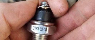
Another repair option is to install a modified crankshaft position sensor from domestic cars:
- We remove the “original” sensor and modify the body of the “donor” part. Most often, this role is played by the DPKV of the ZMZ-406 engine, which has a resistance within 800 Ohms. When remaking, it is necessary to try to ensure that the core is parallel to the wound coil and the toothed ring mounted on the shaft. The distance between the sensor and the ring should be between 0.2 and 0.3 mm.
- Test the operation of the device. On some Japanese vehicles, the ABS warning light may come on intermittently. The situation can be corrected by changing the connection of the wiring contacts.
Both sensor repair options require the owner’s perseverance and ability to work with various tools. If a car user doubts its capabilities, it is recommended to buy a new device or find the product when dismantling cars.
Wiring problem
If the problem with the loss of functionality of the sensor lies in the wiring, it can be replaced:
- Unscrew the sensor holder from the wheel hub.
- Disconnect the cable plug.
- Remove the sensor along with the cable. In this case, it will be necessary to remove the mounting brackets installed on the wiring.
- Measure the installation distances for the brackets. It is recommended to draw a diagram and photograph the factory position of the supports.
- Cut the sensor from the wire, leaving a margin for welding.
- Check the integrity of the cable remaining on the sensor. If the area is not damaged, you can begin installing a new wiring segment.
- Remove all protective covers and fasteners from the old cable.
- Choose a wire with a suitable outer diameter and cross-section.
- Install previously removed guards and fastenings onto the new harness. To facilitate assembly, it is recommended to use a soap solution.
- Solder the sensor and insert it into place.
- Carefully insulate the joint. The tightness of the connection determines the accuracy of operation and service life of the part being repaired.
- Reinstall the sensor, check the functionality of the ABS system, and make sure there are no errors during operation.
What to do first?
It is necessary to check the ABS sensors located near each wheel hub. Your task is to detect a violation in the connection of the sensors, a broken wire or damage to the ABS sensor housing. In any of these cases, you will one way or another see the corresponding indicator on the panel, well, provided that the system control unit itself is working and not “buggy”.
Checking the ABS sensor - measuring the resistance
- We jack up the wheel on which you think the inoperative or faulty sensor is located, or each wheel in turn if you don’t know exactly which sensor is faulty.
- Next, remove the wheel and gain access to the sensor.
- Remove the housing, as well as the protective control unit and connectors that supply power to the sensors.
- After that, we insert wires into the circuit of wires with PIN connectors and connect them with the sensor and multimeter.
- We measure the resistance and compare it with the one that should be by default (you can find it in the manual) or with a representative of the manufacturer of your car.
- We check the wiring for breaks or short circuits.
- Rotate the wheel while watching the multimeter readings, the resistance should change.
- Device - leg - 5-26 Ohm.
- Device - "ground" - from 20 kOhm or more.
For more details on how to check the ABS sensor, watch this video:
Checking the ABS sensor using a tester - measuring the voltage
- Let's jack up the wheel.
- Turn on the multimeter, set the DC voltage measurement mode.
- We connect the electrodes of the device to the connectors and check the readings, while rotating the wheel (about 1 rpm).
- A working ABS sensor will show voltage on the device
0.25-1.2 Volts. If the wheel rotation speed is higher, the readings will increase accordingly.
How to check a sensor with an oscilloscope?
To diagnose the serviceability or malfunction of the ABS sensor, you can even use an oscilloscope or, more simply, a tester. When connected, a graph will be displayed on the device; using amplitude analysis, you can judge the serviceability or malfunction of the sensor.
The problem is that this device is not available at every service station, not to mention the garage in which you are going to conduct all your “experiments”. The device is expensive and quite difficult to understand, so to work with it you need to have certain knowledge and skills.
In modern cars, the ABS system has a self-diagnosis function; using special software, you can read the error code and then decipher it using a special table.
What to do if a breakdown is detected
What to do with the ABS sensor if a malfunction is detected? If the problem point is the device itself, it will have to be replaced, but in the case of electrical wiring, you can fix the defect yourself. To restore its integrity, we use the “soldering” method, carefully wrapping the joints with insulating tape.
If the ABS indicator on the dashboard lights up, this is a clear sign of a sensor failure. The described steps will help identify the cause of the breakdown, but if you lack knowledge and experience, it is better to contact a car service center. Otherwise, illiterate diagnostics of the condition, coupled with improper repair of the device, will reduce the effectiveness of the anti-lock braking system and can provoke an accident.
Source
Varieties of design
To calculate the angular speed of wheel rotation, 2 types of ABS sensor devices can be used:
- based on an inductive element. They are also called passive, since the sensitive element does not require external power, and the operating principle itself is based on the effect of electromagnetic induction. Despite the simplicity of design and reliability, such devices are becoming less and less common on modern cars. The main drawback of the design is that at low vehicle speeds it is impossible to adequately calculate the wheel speed;
- sensors based on the Hall effect. They are also called active, since the sensitive element needs power - a reference voltage. The signal produced by such speed sensors allows the ECU to more accurately calculate the wheel speed.
Design, principle of operation of inductive ABS sensors
Due to the operating principle of electromagnetic induction, the passage of comb teeth mounted on the CV joint body near the iron core provokes voltage surges. Due to the rotation of the wheel, a sinusoidal voltage fluctuation is recorded at the terminals of the ABS sensor; the frequency of the alternating voltage is directly proportional to the angular speed of rotation of the wheel.
The anti-lock brake system control unit registers and compares analog signals from all sensitive elements, which makes it possible to calculate the difference in the angular speeds of rotation of the wheels.
Multimeter test method
If you know how to use a multimeter, then you can check the passive ABS sensor using even the cheapest universal meter. Correspondence of possible faults and methods for their diagnosis:
- open circuit of the coil winding. Set the multimeter to diode testing mode. If the device shows infinite resistance, then there is an open circuit in the circuit;
- unsoldering the coil winding contacts. The nature of the failure is the same as in the case of a break;
- short circuit. To check, switch the multimeter to resistance measurement mode - ohmmeter, measurement range - up to 20 kOhm. Pre-measure the resistance of a previously working sensor or find out the standard value from the technical documentation. Typically, the resistance of serviceable elements ranges from 0.7 to 2.5 kOhm. It is important to take into account that the resistance of working sensors on the front and rear axles can differ significantly.
If the ABS sensor is removed from the car, then you can simulate the rotation of the master disk with any magnetic metal object.
Due to the aggressiveness of the installation environment, ABS sensors on motorcycles may have an electromagnet instead of a permanent magnet, which must be taken into account when checking without dismantling (the ignition must be on).
How to make your search easier
In order not to carry out testing with a tester on each wheel separately, remove the connector of the ABS control unit. The video shows that once you understand the pinout, you can quickly find which circuit has a short circuit or an open circuit.
Application of the Hall effect
The operating principle of the Hall sensor is based on the effect of a transverse potential difference when a conductor with direct current is placed in a magnetic field. A change in the magnetic field when a gear passes near the sensing element provokes the occurrence of rectangular voltage surges. The pulse frequency allows the ABS control unit to calculate the actual wheel speed.
Diagnostic method
Since the operating principle of the ABS sensor is based on the Hall effect, its independent testing is similar to diagnosing the speed sensor used in the speedometer, DPKV. A full check of the correctness of the signal can only be carried out with an oscilloscope, but for simple diagnostics a regular multimeter will do.
To check, you need to switch the tester to DC voltage measurement mode. Connect the test leads to the signal contacts of the sensor, having previously supplied power through an additional resistance (a resistor with a value of 480 Ohms to 1.2 kOhms) and connecting the ground contact to an unpainted part of the car body. If the element is completely faulty, the marker disc rotating with the CV joint will not provoke a change in high and low voltage levels.
Offline check
To operate, the sensitive element requires reference power, so without an external EMF source capable of delivering 9-12 V, it will not be possible to check the ABS sensor with a multimeter. It will also be necessary to include an additional resistor in the circuit (in the case of the Opel Vectra C brake system, as shown in the video, an element with a rating of 680 Ohms will be sufficient). The pinout of the connector can be found in the repair and operating manual for your car.
Since the sensitive element will be removed from the car, you can simulate the rotation of the marker disk by moving the magnet near the sensitive element.
General recommendations for diagnosing the ABS system
If the circuit is broken, the self-diagnosis of the ABS system will necessarily record the fact of a decrease in resistance in the sensor circuit and light up the ABS fault light on the dashboard. Some systems are capable of not only recording the fact of an error, but also calculating which wheel the breakdown occurred on. Therefore, if possible, the first step is to conduct computer diagnostics. On many cars, if more than 1 sensor breaks down, the system lights up not only the ABS fault light, but also the parking brake indicator, after which the ABS turns off.
Before starting diagnostics with a multimeter, make sure that the air gap between the sensor and the marker disk is set correctly, and that the cavities of the marker disk themselves do not have dense dirt or corrosive deposits.
Be extremely careful when removing the sensor. They often stick, but impacts or other use of brute force can damage the plastic case. When installing, ensure that there is a correct air gap between the drive disc and the sensing element.
Ways to check functionality
To determine the condition of a part, we will perform a series of steps to diagnose it, moving from simple to complex:
- Let's check the fuses by opening the unit (inside the passenger compartment or in the engine compartment) and inspecting the corresponding elements (indicated in the repair/operation instructions). If a burnt component is found, we will replace it with a new one.
- Let's inspect and check:
- integrity of connectors;
- wiring for abrasions that increase the risk of a short circuit;
- contamination of the part, possible external mechanical damage;
- fixation and connection to ground of the sensor itself.
If the listed measures do not help to identify a device malfunction, it will have to be checked using instruments - a tester (multimeter) or an oscilloscope.
Tester (multimeter)
This method of diagnosing the sensor will require a tester (multimeter), instructions for operating and repairing the car, as well as PIN - wiring with special connectors.
The device combines the functions of an ohmmeter, ammeter and voltmeter
Tester (multimeter) is a device for measuring electric current parameters, combining the functions of a voltmeter, ammeter and ohmmeter. There are analog and digital device models.
To obtain complete information about the performance of the ABS sensor, you need to measure the resistance in the device circuit:
- We lift the car with a jack or hang it on a lift.
- Remove the wheel if it prevents access to the device.
- Remove the cover of the system control unit and disconnect the controller connectors.
- We connect the PIN to the multimeter and the contact socket of the sensor (the connectors for the rear wheel sensors are located inside the cabin, under the seats).
We connect the PIN to the tester and the contact socket of the sensor
The device readings must correspond to the data specified in the repair and operation manual for a particular vehicle. If the device resistance:
- below the minimum threshold - the sensor is faulty;
- approaches zero - short circuit;
- unstable (jumping) at the moment of twitching of the wire - a violation of contact inside the wiring;
- infinity or no readings - wire break.
Attention! The resistance of the ABS sensors on the front and rear axles is different. The operating parameters of the devices are 1–1.3 kOhm in the first case and 1.8–2.3 kOhm in the second.
Video “Diagnostics of the ABS sensor”
How to check using an oscilloscope (with connection diagram)
In addition to self-diagnosis of the sensor with a tester (multimeter), it can be checked using a more complex device - an oscilloscope.
The device examines the amplitude and time parameters of the sensor signal
An oscilloscope is a device that studies the amplitude and time parameters of a signal, which is intended for accurate diagnosis of pulse processes in electronic circuits. This device detects problems with connectors, broken connections to ground, and broken conductors. The test is performed by visually observing the vibrations on the device display.
To diagnose the ABS sensor with an oscilloscope, you must:
- Fully charge the battery so that during the measurement you can observe voltage drops (jumps) on the connectors or conductors.
- Find the touch sensor and disconnect the upper connector of the part.
- Connect an oscilloscope to the contact socket.
Connecting the device to the ABS sensor connector (1 - toothed disc-rotor; 2 - sensor)
The serviceability of the ABS sensor is indicated by:
- equal amplitude of signal fluctuations when the wheels of one axle rotate;
- absence of amplitude beats when diagnosing with a sinusoid signal of lower frequency;
- maintaining a stable, even amplitude of signal fluctuations not exceeding 0.5 V when the wheel rotates at a frequency of 2 rps.
Note that an oscilloscope is a rather complex and expensive device. Modern computer technologies make it possible to replace this device with a special program downloaded from the Internet and installed on a regular laptop.
Video “Laptop instead of an oscilloscope”
Checking a part without instruments
The easiest way to diagnose a device without instruments is to check the magnetic valve on the induction sensor. Any metal product (screwdriver, wrench) is applied to the part inside which the magnet is installed. If the sensor does not attract it, it is faulty.
Most anti-lock brake systems of modern cars have a self-diagnosis function with errors displayed (in alphanumeric encoding) on the on-board computer screen. You can decipher these symbols using the Internet or the machine’s operating instructions.