About the most important thing! The ignition system in cars of the Samara family is non-contact, and it consists of:
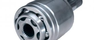
Ignition distributor, also known as distributor:
1. First, let's look at what is included in the main composition of the distributor. Firstly, it includes a hall sensor, and secondly, a centrifugal and vacuum ignition timing regulator, and much more.
3. The ignition distributor is needed to perform two main functions:
- The first function it performs is to set the moment of spark formation, which is carried out depending on the car’s engine speed.
- Its next function is that at the right moment it gives a high voltage pulse, in other words, a spark into the cylinders, depending on the order of their operation.
Note! The ignition distributor supplies a spark to the cylinder using a slider that is installed in the distributor itself, and it is put on the distributor shaft there!
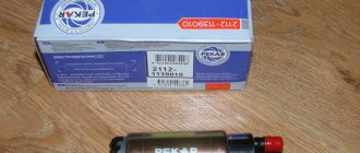
Spark plug:
1. Many people already know why there are spark plugs in a car, but let’s take a closer look.
2. Every gasoline car needs spark plugs, and their job is that with their help, fuel particles in the cylinders burn out in a timely manner, due to the fact that the spark plug gives a spark at the right moment, but where does the spark come from for this spark plug? Yes, everything comes from the same ignition coil, with whose help the car’s engine runs.
3. Spark plugs in cars of the Samara family are used according to the type “A17DVR” as well as “A17DVRM” and “A17DVRM1”. There are other foreign analogues, but these are essentially the most common spark plugs used in these cars.
4. Sometimes there comes a time when the spark plugs, so to speak, become obsolete, and therefore they need to be periodically every 30,000 km. replace with new ones. If you still have to replace them, then we have prepared an article for you in which you will find detailed instructions on how to replace them. (see Replacing spark plugs)
Ignition coil:
1. The coil, as it is popularly called, performs the function of converting a low voltage current into a high voltage current, below we will analyze all this in detail.
2. First, understand once and for all that the ignition coil is essentially an element that works due to the battery, and several other factors. The principle of operation of the coil is as follows:
- First, current is supplied to the coil from the battery.
- After the coil has received current, it converts it into high voltage current, the voltage of which reaches about 25,000 - 35,000 volts.
- Then, after converting the high voltage current, it directs this current to the spark plugs, through the high voltage wires.
- And after the spark plugs have received current, they then use it to produce a spark when the piston approaches top dead center (TDC).
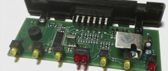
Switch:
1. It is a kind of small module, due to which the following is carried out:
- Current stabilization, that is, in other words, the switch prevents the current from falling below “6 Volts”, and it also prevents the conversion of current above “18 Volts”. Thanks to these actions, the wires of the contactless ignition system burn out much less often.
- It also creates current pulses in the ignition coil.
- It also protects parts from overheating and overload, so they will last a longer life.
- And in addition to all this, the switch de-energizes the ignition in the car at the moment when you turn off the car engine.
2. On cars of the Samara family, switches of the type “3620.3734”, as well as “76.3734” are installed; switches of the type “RT1903” and “PZE4022” are also subject to installation.
3. If the switch fails, it cannot be repaired. If you begin to notice that the switch is becoming unusable, it is recommended to replace it with a new one.
4. It is forbidden to disconnect the block of wires that is connected to the switch when the car’s ignition is on, because this can damage it, and damage to other parts of the ignition system may also occur.
Ignition switch:
1. The switch is a lock, which you have all already seen in every car. Thanks to this switch, you can turn on and off the ignition system devices.
2. The switch includes an individually selected key with which we can turn this switch. And in the switch body there is a fixed disk with terminals and contacts, and the wires that come from the ignition coil are connected to this disk.
3. When the key is removed from the lock, all contacts subsequently open. And when the key is inserted into the cylinder and then turned, in this case all contacts are closed, and therefore the ignition in the car is turned on.
Low and high voltage wires:
High voltage wires:
1. High-voltage wires serve to transmit high-voltage current from the ignition coil itself and to each cylinder spark plug.
2. Cars of the Samara family are equipped with high-voltage wires with a distributed resistance of 2550±270 Ohm/m.
3. Under no circumstances try to start a car with a broken high-voltage voltage circuit, that is, to put it simply: The car’s engine does not need to be started with the high-voltage wires removed, as well as with the ignition distributor cap removed. Such actions can lead to failure of the ignition system elements, as well as breakdown of the insulation, so be careful.
4. It is also not recommended to handle or touch high voltage wires when the car engine is in working condition, because this can lead to electrical injury.
Note! When checking high-voltage wires for the presence of a spark, it is recommended to disconnect the wires with the engine turned off, and if the engine is started, the wires should be secured at a distance of 5-10 mm from the mass of the car, and these wires should not be in your hands, even in only if you hold them with a tool!
Low voltage wires:
1. Every person has encountered such wires in his life; they are most often of small thickness and have a very flexible shape, unlike high-voltage wires.
2. And most often, low-voltage wires have a combined color, that is, they come in both red and blue, and have many other colors.
3. A striking example of where the low voltage wires are connected is the same ignition coil, because if you look at it carefully, then on its side you can see two wires, one of which is “red” and the other “blue”. (see photo above)
This is interesting: Why Vesta turned out to be more popular than X-Ray: comparative analysis
Ignition adjustment
In cases where, during reassembly, you forgot about the marks or turned the shaft, as a result of which the piston left TDC, you will have to spend quite a lot of time re-setting the ignition.
Before you begin work, you must:
IMPORTANT! The speed of the car engine should be in the range of 820 – 900 rpm
- At idle speed, set the ignition timing and check it.
- The value of the set angle is 0 - 1 degree, counting from TDC. The consequences of incorrect ignition installation will be engine overheating and a significant reduction in its power, as well as detonation. The latter leads to accelerated destruction of the cylinder rings and increased fuel consumption
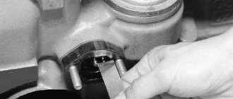
- The adjustment mentioned above is carried out on a scale located in a special hatch provided in the clutch housing (the rubber plug must be removed). And according to the mark applied to the flywheel at the factory
Next comes the actual adjustment procedure. But this is the topic of a separate article, which you can read on our website. A video is also posted here, which is step-by-step instructions for eliminating this problem and corresponding photos. In the event that you plan to fix the malfunction at a service station, the price of the work must be specified additionally.
Ignition circuit for VAZ 2109
Every owner of the VAZ 2109 should know the ignition circuit Without knowing this circuit, you will not be able to start the car in case of ignition problems. Moreover, this scheme is elementary simple. The VAZ 2109 is equipped with a contactless ignition system. It consists of the following components: switch, ignition coil, distributor, Hall sensor, high-voltage wires and spark plugs. The task of the ignition system is to provide a timely, cyclic spark to the engine cylinders. Let's take a closer look at how the clamping circuit works.
Ignition circuit for VAZ 2109
ignition of the VAZ 2109: power is supplied to the ignition system through a relay. Until the key is in the ignition position, the relay will not turn on and supply power to the circuit. As soon as the key is turned, the ignition system is energized. +12V power from the battery is supplied to contact B of the ignition coil, the 4th contact of the switch. The Hall sensor powers the switch itself. Please note that the ignition relay is powered through the mounting block, and if there is poor contact in connectors Ш1, Ш8 or for some reason the track oxidizes or burns out, the ignition system will not be powered and the VAZ 2109 will not start. In order for a spark to begin to form, you need to crank the engine crankshaft. Together with it, the camshaft will turn and the Hall sensor will send an impulse to the switch. The commutator, in turn, will connect contact K of the ignition coil to ground, resulting in a spark appearing on the central wire. When the distributor slider connects the central wire and the wire leading to a specific engine cylinder, a spark will jump on the spark plug, igniting the combustible mixture. The engine will start. When it is necessary to turn off the engine, the driver, by turning the key in the ignition switch, turns off the relay, which in turn disassembles the power supply to the system. The switch and ignition coil become de-energized and stop working. The most common malfunctions of the VAZ 2109 ignition system: 1) Failure of the switch. 2) Failure of the Hall sensor. 3) Poor contact of the slider in the distributor. 4) Lack of power supply to the ignition system of the VAZ 2109. Go to Home.
Checking the operation of the circuit
If signs indicating a malfunction of the Hall sensor appear, it is checked without removing it from the distributor. There are several ways to do this:
- 1. To check, you need to have a voltmeter and several pins. The check is carried out in the following order:
- pierce the insulation of the green and black and white wires going to the sensor connector with pins;
- connect the pins to the voltmeter using connecting wires with clamps;
- turn on the ignition;
- slowly turn the engine crankshaft. To do this, you need to rotate the flywheel through the hatch in the clutch housing;
- monitor the readings of the measuring device. If the sensor is working properly, then the voltage on the voltmeter periodically disappears almost completely (0.4 V), and then changes to 9...12 V. Otherwise, it must be replaced.
- 2. In the absence of a voltmeter, the test can be carried out in the following way:
- disconnect the central high-voltage wire from the distributor cover;
- secure this wire so that its tip is located at a distance of 5...10 mm from the main brake cylinder;
- Using a piece of any wire, connect the central contact of the high-voltage wire to the negative terminal of the car battery. If a spark “jumps” between the central wire and the brake cylinder, it means the sensor is faulty and must be replaced.
Lada 2109 › Logbook › Dual-circuit ignition on the VAZ 2109
I suffered several times in the winter with starting the engine. Even when it’s not cold, but at 0 degrees, you come to start it and the car is silent. You unscrew the damp spark plugs and the battery eventually dies! With a good battery, it starts normally. As it turned out in the end, I had a contact ignition coil B- 117 from the classics. I immediately changed it to a coil from BSZ. And the car started to start and drive much better, but I didn’t stop there and decided to make a dual-circuit ignition with 2 hall sensors, 2 switches and 2 coils from the Volga ZMZ- 406
To begin with, I began to assemble the distributor because it is the most basic and subtle part of the system. I took the distributor from OKI as a basis, or an ordinary nine-wheel one. I just had it from the window and was lying in the garage. I completely disassembled it and started installing the 2nd hall sensor directly on the standard platform at an angle of 90 degrees. I marked out the approximate position of the 2nd sensor There are risks at the site regarding the approximate position of the middle of the sensor:
Drilled and tapped the threads for the bolts:
Then I carefully cut the hall sensors themselves with a metal cloth so that they do not interfere with each other. It looks something like this:
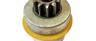
Then I modified the shaft, replaced the ignition angle advance weights with nine-shaft ones. They are smaller and lighter than those of the Oka, the photo shows Okushinsky weights! And accordingly, I also replaced the springs. The curtain remained the standard Okushenskaya one, I didn’t touch it. If you make it from a nine-shaft shaft, then you need a curtain too modify it by sawing off two opposite ones so that it looks like in the photo:
That's all for the shaft! Next, I cut out a small piece from the distributor body itself to attach the fork of the 2nd hall sensor, drilled a hole and cut a thread for the bolt
Then I put the whole thing together. Here’s what happened:
Note: during assembly it turned out that the platform on which the hall sensors from the Oka are attached is larger than from the 2109 and it turned out to be easier to mount the sensor, so another one +, It is advisable to buy the same sensors themselves in the same store from the same batch as they are slightly different! That's all for now with the distributor!
Then I bought the rest of the necessary parts: 2 coils from the Volga ZMZ-406, a wiring harness for the BSZ 2108, an “Astro” switch, as I already had the same one
I connected the wiring according to the diagram:
Note: when connecting according to scheme 1, the tachometer will show half the revolutions. If you want to make a normal tachometer, then there is also scheme 2, there you will need to solder 2 KD213A diodes. But I did not do this and did it according to scheme 1. And don’t try to connect wires without diodes according to scheme 2, as you parallel both coils and it turns out that all 4 spark plugs spark simultaneously when both hall sensors are triggered! Tested personally)
I made a metal mount for the coils, but it didn’t turn out very well:
And now about the most important thing: for the system to work well, you need to adjust the synchronization of the hall sensors so that the spark on all cylinders is the same advance. To do this, you need to make the opposite mark on the flywheel, this will be the TDC of the 2nd cylinder. You need to count 64 teeth along the crown from the standard mark .And using a strobe light, combine both marks from the 1st and 2nd cylinders, moving the 2nd hall sensor up and down or both sensors in the direction of the white arrows. To do this, I drilled holes with a thin drill in the sensors to move them.
Diagram of the ignition system for VAZ 2108, 2109, 21099 cars
Diagram of the contactless ignition system for VAZ 2108, 2109, 21099 cars
Elements of the ignition system for VAZ 2108, 2109, 21099 cars
- Accumulator battery.
Provides electrical current when starting the engine.
Provides electric current when the car engine is running. In particular, it powers the ignition system.
- Fuse and relay mounting block.
Serves for switching low voltage wires, in particular the ignition system.
- Ignition coil.
Provides high voltage current to the ignition distributor.
Provides a pulse for sparking (opening the power circuit of the primary winding of the ignition coil) in one or another cylinder according to a signal from the Hall sensor.
Generates a control pulse (reducing voltage) for the switch, signaling the need for sparking in one or another engine cylinder.
- Ignition distributor (distributor) with vacuum and centrifugal ignition timing regulators.
Serves to generate a control pulse to the switch (Hall sensor), distribute high voltage pulses across the spark plugs (“slider”), correct the ignition timing in accordance with the engine operating mode (centrifugal and vacuum regulators).
- High-voltage wires (armored wires).
They serve to transmit high voltage current from the ignition coil to the distributor cover and then to the spark plugs.
- Egnition lock.
Serves to close the ignition system circuit. Through it, electric current flows into the ignition system.
- Ignition relay.
This is interesting: What happens if the airbag goes off a moment later?
Serves to relieve the contacts of the ignition switch (lock) and supply voltage to the coil and switch.
- Spark plug.
Serve to generate a spark in the engine cylinders.
Notes and additions
More articles on the ignition system
How to test a switch
On average, the cost of this part is not too high, but many car owners, for various reasons, do not seek to replace it. In addition, if you change a known-good switch, problems with the engine will remain, because the cause of malfunctions in the operation of the power plant may be completely different. Therefore, the optimal solution would be to check the part for functionality.
For accurate diagnostics, you will need special professional equipment, which is available at any service station. On a special stand you can check the pulse on the ignition coil, its stability and cyclicity. However, it is not always possible to turn to specialists; there is also a simpler folk diagnostic method. To check, you should take a key for an 8 and 12-volt light bulb with a power of 3 W. The algorithm of actions is as follows.
- Disconnect the power supply by disconnecting the terminals from the battery.
- Using a key number 8, you need to disconnect the brown wire that goes from terminal K on the ignition coil to terminal 1 on the switch.
- One contact of the control light is connected to the terminal on the ignition coil, and the other to the switch. As a result, the control lamp becomes part of the circuit between the coil and the switch.
- Connect the terminals to the battery and try to start the engine (the lamp should light up while the starter rotates).
A light that comes on indicates that the switch is working properly. If this does not happen, the unit is faulty and needs to be replaced. When disconnecting the light bulb, be sure to disconnect the negative terminal from the battery, thereby preventing the possibility of an accidental short circuit.
The installation location of the device is a partition separating the engine compartment of the car from its interior. The device is mounted in the engine compartment. The connection diagram of the switch must ensure reliable contact between the base of the device and the car body. The device can operate normally up to a heating temperature of 115 °C.
Features of the operation of different ignition systems
Ignition on the VAZ 2109 is necessary to ignite the air-fuel mixture when starting the engine. If the ignition does not work correctly, the engine will start and run intermittently, and its power during start-up and acceleration will noticeably decrease. In addition, fuel consumption will be noticeably increased. The conclusion from this is that the correct operation of the ignition system should be constantly monitored.
It’s worth mentioning right away the differences in the ignition design of “nines” with different types of fuel supply. Their SZ is similar, but they differ in the elements of electric charge distribution.
- In “nines” equipped with a carburetor, there is a coil and a distributor.
- For systems with an injector, an ignition distribution module consisting of several coils and an electronic controller is installed.
The second difference is how the system works. In cars with an injector it is not required, but in VAZs with a carburetor you have to do it manually.
In nines, two types of ignition systems are used:
- contact;
- contactless with transistors.
The first is installed in carburetor “nines”, and the second in injection ones. Thanks to the use of contactless ignition, the system has the following advantages:
- Working with a Hall sensor, which makes the system more stable and increases its overall efficiency.
- The absence of contact with the working parts and elements of the system increases the service life of the elements and makes maintenance of the circuit components easier.
- Excellent spark distribution between spark plugs.
- Generating a powerful spark, which prevents system failures.
- Fuel economy.
- Works even with low battery charge.
Over time, the contact type SZ has practically ceased to be used, so from now on we will focus on the contactless analogue.
How does the scheme work?
The contactless ignition system of the VAZ 2109 has a fairly simple operating principle, based on the sequential inclusion of various elements in the design. The electronic components of the circuit regulate the formation and supply of sparks to the working bodies. All this works according to the following principle:
- The rotation of the starter drives the camshaft, which in turn starts the distributor.
- The distributor contains a Hall sensor, near which there is a device with a hole. It serves to create a signal under the influence of a magnetic field.
- The electrical signal from the distributor goes to the switch.
- From the commutator, energy is supplied to a coil of two windings. There is a multiple increase in the charge, after which it goes to the ignition distributor.
- The current is distributed through the spark plugs, and the air-fuel mixture ignites.
To ensure proper spark distribution, the following occurs:
- A sensor located near the crankshaft transmits a signal to system monitoring devices.
- The controllers, in turn, process the received information and create the order in which current is supplied from the coils to the spark plugs.
- The coils create sparks - one to ignite the air-fuel mixture, the second to idle.
Return to contents
Replacement
In order to replace the Hall sensor, it is necessary to dismantle the distributor. Having removed it from the VAZ 2108, you then need to carry out the following operations:
- remove the slider by pulling it up;
- remove the protective cover;
- disconnect the connector connected to the sensor by unscrewing the fastening bolt;
- Unscrew the two screws securing the support plate using a screwdriver;
- dismantle the vacuum corrector. To do this, you need to unscrew the fastening screws, remove the locking pin and disconnect the rod;
- remove the support plate;
- unscrew the two mounting screws and remove the faulty sensor;
- Install a new one and reassemble the distributor in the reverse order;
- Install the distributor back into the engine compartment of the VAZ 2108.
The connector from the Hall sensor can only be disconnected after the ignition is turned off.
Circuit parameters, its components
The ignition system circuit consists of:
- candles;
- switch;
- distributor;
- ignition relay VAZ 2109;
- coils;
- switch;
- blocking devices (does not allow starting a repeat cycle until the previous one is completed);
- anti-theft mechanism;
- Hall sensor;
- sensor-distributor mechanism (receives rotation from the camshaft);
- automatic circuit shutdown device, triggered within 8 seconds;
- current rectifier;
- systems for regulating the amount of energy in the switch.
What is an ignition module called? The ignition module on a VAZ is a coil, switches, and an ECU, enclosed in one plastic housing. Where is this module located? Open the hood of the car, look for high-voltage wires - spark plugs are located at one end of the conductors, and a module at the other.
Incorrect operation of this device leads to the inability to start the engine or to its deteriorated performance. The ignition module of the VAZ 2109 injector does the job of creating a spark and its correct distribution; it has a vacuum ignition timing regulator, so it does not need to be adjusted, unlike the circuit in the “nines” with a carburetor.
Setting up SZ
If you have a VAZ 2109 carburetor, you will have to adjust the ignition system from time to time. This procedure is not the simplest; it requires following clear instructions. The operating procedure is as follows:
- We take the manual for our “nine” in our hands, set the contact gaps in accordance with the recommended values. Typically this is 0.45 mm.
- The ignition timing is set using special equipment, we miss this point.
- We connect the high-voltage wires and begin adjusting the torque in the middle of the stroke.
- Install the spark plug in the first cylinder and turn on the ignition.
- Turn the pulley counterclockwise 45°.
- We connect the ground to the spark plug, turn the pulley gradually in a clockwise direction until a spark appears between the electrodes.
- We look at the marks of the cover and pulley. They must be on the same level.
- To ensure that the marks coincide, we turn the distributor in the desired direction.
- If the marks do not match, the ignition will either be late or turn on prematurely, which is unacceptable.
- We rotate the pulley and distributor until we get the desired result, after which the distributor will need to be tightened, and then turn the crankshaft two turns.
- Check the result: if everything works fine, we finish the adjustment.
- You need to warm up the engine, then drive at a speed of 40-50 km/h, switch to fourth gear and accelerate sharply. If there is a knock, the ignition worked prematurely, we adjust it again.
At the service station, technicians can also carry out the adjustment, so if you can’t do it yourself, go there.