The task of the VAZ 2107 ignition system is to generate a spark that ignites the air-fuel mixture in the cylinders. In older “classic” models, this works based on the “breaker-ignition coil” connection. On more modern cars, a contactless ignition system is installed, where the VAZ 2107 ignition switch is responsible for sparking.
Switch malfunctions affect the efficiency and performance of the entire ignition system and the vehicle as a whole. Therefore, it will not be superfluous to learn how to check the VAZ 2107 switch and replace it, if necessary.
Diagram of the contactless ignition system for VAZ 2108, 2109, 21099 cars
VAZ 2108, 2109, 21099 cars and their modifications use a non-contact ignition system. There is no breaker (as in the contact system). The moment of sparking is controlled electronically. Below is its electrical diagram and a description of the main elements.
Elements of the ignition system for VAZ 2108, 2109, 21099 cars
- Accumulator battery.
Provides electrical current when starting the engine. "VAZ battery"
Generator.
Provides electric current when the car engine is running. In particular, it powers the ignition system.
- Fuse and relay mounting block.
Serves for switching low voltage wires, in particular the ignition system.
- Ignition coil.
Provides high voltage current to the ignition distributor. “Ignition coil wires for VAZ 2108, 2109, 21099”
Provides a pulse for sparking (opening the power circuit of the primary winding of the ignition coil) in one or another cylinder according to a signal from the Hall sensor.
Generates a control pulse (reducing voltage) for the switch, signaling the need for sparking in one or another engine cylinder.
- Ignition distributor (distributor) with vacuum and centrifugal ignition timing regulators.
Serves to generate a control pulse to the switch (Hall sensor), distribute high voltage pulses across the spark plugs (“slider”), correct the ignition timing in accordance with the engine operating mode (centrifugal and vacuum regulators).
- High-voltage wires (armored wires).
They serve to transmit high voltage current from the ignition coil to the distributor cover and then to the spark plugs.
- Egnition lock.
Serves to close the ignition system circuit. Through it, electric current flows into the ignition system.
- Ignition relay.
Serves to relieve the contacts of the ignition switch (lock) and supply voltage to the coil and switch.
- Spark plug.
Serve to generate a spark in the engine cylinders.
Notes and additions
— This scheme of a contactless ignition system is applicable on VAZ 2108, 2109, 21099 cars produced before 1998. On cars after 1998. it's similar. The difference is in the names of the mounting block pads (Ш1 - Х1, Ш8 - Х8).
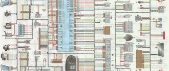
Electrical wiring diagrams
2108 with low instrument panel with mounting block type 17.3722
1 – block headlight; 2 – gear motor for headlight cleaner*; 3 – engine compartment lamp switch; 4 – sound signal; 5 – electric motor of the engine cooling system fan; 6 – fan motor activation sensor; 7 – generator; 8 – solenoid valve for turning on the headlight washers*; 9 – solenoid valve for turning on the rear window washer* (not installed on the VAZ-21099); 10 – solenoid valve for turning on the windshield washer; 11 – electric motor for glass washer; 12 – oil pressure warning lamp sensor; 13 – carburetor solenoid valve; 14 – carburetor limit switch; 15 – spark plugs; 16 – plug socket for a portable lamp; 17 – engine compartment lamp; 18 – ignition distributor sensor; 19 – carburetor solenoid valve control unit; 20 – windshield wiper gearmotor; 21 – switch; 22 – ignition coil; 23 – starter; 24 – top dead center sensor of the 1st cylinder**; 25 – diagnostic block**; 26 – starter activation relay; 27 – coolant temperature indicator sensor; 28 – reverse light switch; 29 – battery; 30 – brake fluid level sensor; 31 – mounting block; 32 – parking brake warning lamp switch; 33 – brake light switch; 34 – glove box lighting lamp; 35 – heater fan electric motor; 36 – additional resistor of the heater electric motor; 37 – heater fan switch; 38 – backlight lamp for heater levers; 39 – cigarette lighter; 40 – rear window heating switch; 41 – rear fog light switch; 42 – fog light circuit fuse; 43 – alarm switch; 44 – external lighting switch; 45 – ignition relay; 46 – ignition switch; 47 – steering column switch; 48 – instrument lighting switch; 49 – side direction indicator; 50 – lamp switch on the front door pillar; 51 – lamp switch on the rear door pillar (not installed on VAZ-2108 and VAZ-21083); 52 – lampshade; 53 – sockets for connecting individual interior lighting to the lampshade; 54 – switch for the carburetor air damper warning lamp; 55 – turn signal indicator lamp; 56 – indicator lamp for external lighting; 57 – rear fog light indicator lamp; 58 – backup warning lamp; 59 – control lamp for high beam headlights; 60 – indicator lamp for heated rear window; 61 – speedometer VAZ 2108; 62 – instrument cluster; 63 – instrument cluster lighting lamps; 64 – coolant temperature indicator; 65 – voltmeter; 66 – fuel level indicator with reserve indicator lamp; 67 – econometrician; 68 – “STOP” indicator lamp; 69 – battery charge indicator lamp; 70 – control lamp for the carburetor air damper; 71 – hazard warning lamp; 72 – brake fluid level warning lamp; 73 – parking brake warning lamp; 74 – oil pressure warning lamp; 75 – rear light; 76 – sensor for level indicator and fuel reserve; 77 – pads for connecting to the rear window heating element; 78 – license plate lights; 79 – rear window wiper gear motor* (not installed on VAZ-21099)
* Installed on parts of manufactured cars. ** Not installed since 1995
2108 with high instrument panel with mounting block type 17.3722
1 – block headlight; 2 – gear motor for headlight cleaner; 3 – fog lamp; 4 – sound signal; 5 – electric motor of the engine cooling system fan; 6 – engine compartment lamp switch; 7 – fan motor activation sensor; 8 – wire lugs connected to sensor 7 in case of installation of a mounting block type 17.3722; 9 – connectors for connecting to front brake pad wear sensors; 10 – washer fluid level sensor; 11 – solenoid valve for turning on the headlight washer; 12 – solenoid valve for turning on the rear window washer (not installed on the VAZ-21099); 13 – solenoid valve for turning on the windshield washer; 14 – windshield washer motor; 15 – oil level sensor; 16 – generator; 17 – oil pressure warning lamp sensor; 18 – carburetor limit switch; 19 – spark plugs; 20 – carburetor solenoid valve; 21 – engine compartment lamp; 22 – ignition distributor sensor; 23 – carburetor solenoid valve control unit; 24 – windshield wiper gearmotor; 25 – ignition coil; 26 – starter; 27 – switch; 28 – starter activation relay; 29 – coolant temperature indicator sensor; 30 – brake fluid level sensor; 31 – reverse light switch; 32 – battery; 33 – relay for turning on fog lights; 34 – coolant level sensor; 35 – mounting block; 36 – parking brake warning lamp switch; 37 – brake light switch; 38 – door lock control unit; 39 – cigarette lighter; 40 – glove box lighting lamp; 41 – heater fan electric motor; 42 – additional resistor of the heater electric motor; 43 – heater fan switch; 44 – backlight lamp for heater levers; 45 – gearmotors for electric windows of the front doors; 46 – gearmotors for locking front door locks; 47 – gearmotors for locking rear doors; 48 – headlight cleaner switch; 49 – power window switch for the right front door; 50 – ignition switch; 51 – power window switch of the left front door; 52 – ignition relay VAZ 2108; 53 – pads for connecting to the heating elements of the front seats; 54 – right front seat heating switch; 55 – left front seat heating switch; 56 – relay for turning on the heating of the front seats; 57 – front seat heating circuit fuse; 58 – instrument lighting switch; 59 – steering column switch; 60 – indicator lamp for turning on the heated rear window; 61 – rear window heating switch; 62 – control lamp for turning on fog lights; 63 – fog lamp switch; 64 – indicator lamp for turning on the rear fog light; 65 – rear fog light switch; 66 – side direction indicator; 67 – lamp switch on the rear door pillar (not installed on VAZ-21083); 68 – lamp switch on the front door pillar; 69 – canopy for individual interior lighting; 70 – lampshade; 71 – external lighting switch; 72 – instrument cluster; 73 – switch for the carburetor air damper warning lamp*; 74 – alarm switch; 75 – warning lamp for turning on the hazard warning lights; 76 – block for connection to the trip computer; 77 – rear light; 78 – block for connection to the rear window heating element; 79 – rear window wiper motor reducer (not installed on VAZ-21099); 80 – blocks for connecting to an additional brake light; 81 – license plate lights; 82 – level indicator and fuel reserve sensor
* Not installed on vehicles equipped with a carburetor with a semi-automatic starting device.
2108 with high instrument panel with mounting block type 2114-3722010
1 – block headlight; 2 – gear motor for headlight cleaner; 3 – fog lamp; 4 – sound signal; 5 – electric motor of the engine cooling system fan; 6 – engine compartment lamp switch; 7 – fan motor activation sensor; 8 – wire lugs connected to sensor 7 in case of installation of a mounting block type 17.3722; 9 – connectors for connecting to front brake pad wear sensors; 10 – washer fluid level sensor; 11 – solenoid valve for turning on the headlight washer; 12 – solenoid valve for turning on the rear window washer (not installed on the VAZ-21099); 13 – solenoid valve for turning on the windshield washer; 14 – windshield washer motor; 15 – oil level sensor; 16 – generator; 17 – oil pressure warning lamp sensor; 18 – carburetor limit switch; 19 – spark plugs; 20 – carburetor solenoid valve; 21 – engine compartment lamp; 22 – ignition distributor sensor; 23 – carburetor solenoid valve control unit; 24 – windshield wiper gearmotor; 25 – ignition coil; 26 – starter; 27 – switch; 28 – starter activation relay; 29 – coolant temperature indicator sensor; 30 – brake fluid level sensor; 31 – reverse light switch; 32 – battery; 33 – relay for turning on fog lights; 34 – coolant level sensor; 35 – mounting block; 36 – parking brake warning lamp switch; 37 – brake light switch; 38 – door lock control unit; 39 – cigarette lighter; 40 – glove box lighting lamp; 41 – heater fan electric motor; 42 – additional resistor of the heater electric motor; 43 – heater fan switch; 44 – backlight lamp for heater levers; 45 – gearmotors for electric windows of the front doors; 46 – gearmotors for locking front door locks; 47 – gearmotors for locking rear doors; 48 – headlight cleaner switch; 49 – power window switch for the right front door; 50 – ignition switch; 51 – power window switch of the left front door; 52 – ignition relay; 53 – pads for connecting to the heating elements of the front seats; 54 – right front seat heating switch; 55 – left front seat heating switch; 56 – relay for turning on the heating of the front seats; 57 – front seat heating circuit fuse; 58 – instrument lighting switch; 59 – steering column switch VAZ 2108; 60 – indicator lamp for turning on the heated rear window; 61 – rear window heating switch; 62 – control lamp for turning on fog lights; 63 – fog lamp switch; 64 – indicator lamp for turning on the rear fog light; 65 – rear fog light switch; 66 – side direction indicator; 67 – lamp switch on the rear door pillar (not installed on VAZ-21083); 68 – lamp switch on the front door pillar; 69 – canopy for individual interior lighting; 70 – lampshade; 71 – external lighting switch; 72 – instrument cluster; 73 – switch for the carburetor air damper warning lamp*; 74 – alarm switch; 75 – warning lamp for turning on the hazard warning lights; 76 – block for connection to the trip computer; 77 – rear light; 78 – block for connection to the rear window heating element; 79 – rear window wiper motor reducer (not installed on VAZ-21099); 80 – blocks for connecting to an additional brake light; 81 – license plate lights; 82 – level indicator and fuel reserve sensor
Useful: VAZ tachometer connection diagram
* Not installed on vehicles equipped with a carburetor with a semi-automatic starting device.
The switch is. Switch diagram. How to check the ignition switch
The switch is an electronic component to ensure the operation of a contactless ignition system. It is transitional between contact and microprocessor. The latter, the most advanced, allows you to control the torque using data read from sensors - oxygen, speed, engine speed and others. But there are still many cars on the roads that have both contact breakers and contactless ones. Therefore, for maintenance and diagnostics, you need to know the purpose of all elements, as well as troubleshooting methods and their main symptoms. Before testing the switch, review all parts carefully.
Alternative diagnostic methods
When there is no voltmeter on the dashboard, you can get out of the situation by doing everything yourself. To do this, you will need a 12 V light bulb and two meter wires with stripped ends. The diagnostic work flow diagram is as follows:
- disconnect the battery, de-energize the electrical system;
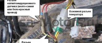
- using a size 8 wrench, unscrew the nut and remove the wire from the ignition coil terminal marked “K”, this wire is brown and goes to the clamp marked “1” on the switch;
- connect this wire to one of the test lamp wires;
- Connect the other wire of the control lamp to terminal “K” on the ignition coil;
- connect the battery;
- Turn on the engine starter and observe the condition of the lamp. If the lamp is flashing, the device is working properly. If the lamp does not light, the device is faulty.
There is another simple and reliable way to identify a device malfunction. To do this, you need to install a known-good switch, start the car and check the functionality of the system in all modes. If the system is working normally, then the problem was precisely the failure of this device, and when the same failures occur, the switch has nothing to do with it.
The disadvantage of this method is that you need to have a spare working switch with you. While this is reasonable for long journeys in uncrowded areas, it is exotic for regular city trips.
Contactless ignition system
In total, there are three huge groups of systems - contact, contactless, microprocessor. The first is divided into two subgroups - contact and using a transistor operating in switch mode. Transistors are also used in the design of a contactless ignition system. This scheme began to be actively used in the early 80s of the last century. And it has a number of advantages, which will be discussed below. The switch circuit is simple; it can be implemented both on transistors and on a controller.
But the contactless ignition system also has many disadvantages when compared with a microprocessor one. The latter allows you to control almost all engine parameters. BSZ does not allow this; it also cannot be used normally on injection engines. The reason for the obsolescence of the contactless system lies not only in the development of electronics and the automotive industry, but also in the adoption of stringent measures to ensure the environmental friendliness of internal combustion engines. Unfortunately, only microprocessor control can reduce the amount of harmful substances in the exhaust.
Main elements of the system
Of course, the first thing to mention is the spark plugs. They are installed in the cylinder head, the electrodes come out from the inside. These are the elements that allow the air-fuel mixture to ignite. But with the help of spark plugs alone, the engine will not be able to run. It is necessary to monitor the position of the crankshaft in order to know in what position the pistons are in the cylinders.
For this purpose, an inductive sensor operating on the Hall effect is used. It is part of the design of another element - the ignition distributor. The sensor produces a pulse that is sent to the switch. This device allows you to amplify a weak signal to a voltage of 12 volts, and then apply it to a coil. A coil is nothing more than a simple transformer (step-up). Its secondary winding has a greater number of turns than the primary. Due to this, the voltage increases and the current decreases. The voltage in the BSZ is supplied to the spark plugs at a value of 30-35 kV (depending on the car model).
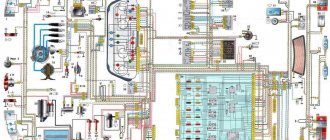
Electrical diagram of VAZ 21083
1- block headlight; 2- electric motors for headlight cleaners; 3- fog lights; 4- engine compartment lamp switch; 5 - sound signal; 6- electric motor of the engine cooling system fan; 7- fan motor activation sensor; 8- front brake pad wear sensor; 9- generator; 10 - solenoid valve for turning on the headlight washers; 11- solenoid valve for turning on the rear window washer; 12- solenoid valve for turning on the windshield washer; 13- glass washer motor; 14- oil pressure warning lamp sensor; 15- oil level sensor; 16- washer fluid level sensor; 17 - fuel consumption sensor; 18- carburetor solenoid valve; 19- carburetor limit switch; 20- starter enable relay; 21- spark plugs; 22- ignition distributor sensor; 23 - vehicle speed sensor; 24- carburetor solenoid valve control unit; 25- diagnostic block; 26- ignition coil; 27- reverse light switch; 28 - coolant temperature indicator sensor; 29- starter; 30 - top dead center sensor of the 1st cylinder; 31- switch; 32- battery; 33- coolant level sensor; 34- relay for turning on fog lights; 35- brake fluid level sensor; 36- mounting block; 37-plug socket for a portable lamp; 38- door lock control unit; 39- engine compartment lamp; 40- electric motor for windshield wiper; 41- glove compartment lighting lamp; 42- heater fan electric motor; 43- additional resistor of the heater electric motor; 44- heater fan switch; 45- heater backlight lamp; 46- gearmotors for electric windows of the front doors; 47- gearmotors for blocking door locks; 48- ignition switch; 49- right door power window switch; 50- left door power window switch; 51- ignition relay; 52- steering column switch; 53- trip computer; 54- cigarette lighter; 55 - instrument lighting regulator; 56- parking brake warning lamp switch; 57- brake light switch; 58 - indicator lamp for turning on the heated rear window; 59- rear window heating switch; 60 - fog light switch; 61 - control lamp for turning on fog lights; 62 - indicator lamp for turning on the rear fog light; 63- rear fog light switch; 64- side direction indicators; 65 - lamp switch on the door pillars; 66- fog light circuit fuse; 67 - external lighting switch; 68 - instrument cluster VAZ 2108; 69- carburetor air damper warning lamp switch; 70- hazard switch; 71- lampshade; 72- connector for connecting to an individual lighting lamp; 73- rear lights; 74- license plate light; 75 - rear window wiper motor; 76 - rear window heating element; 77 - level indicator and fuel reserve sensor.
The numbering order of the plugs in the blocks is: A – mounting block, instrument cluster, steering column switch, ignition switch and windshield wiper; B – headlight and rear window cleaners; B – speed and fuel consumption sensor and in the ignition distributor; G – gear motors for power windows and gear motors for locking door locks.
Full size diagram:
How is BSZ better than contact?
Having carefully read the previous section, you can see that the system uses an inductive non-contact Hall sensor. The advantage is obvious - there is no friction and commutation. For comparison, look at the contact system. In it, the breaker switches the voltage, the value of which is 12 Volts. Whatever one may say, the metal contacts are constantly in contact with each other, gradually wear out, and become covered with soot.
For these reasons, it is necessary to constantly monitor the breaker, adjust the gap, and carry out timely replacement. BSZ is devoid of these shortcomings, therefore, without third-party intervention, the system operates much longer. The Hall sensor fails very rarely, as does the switch. This increases the reliability of the system, but precautions must also be taken, in particular, the connection of the switch to the body must be as tight as possible to ensure effective heat exchange. In addition, BSZ allows you to improve engine performance, increase, albeit slightly, its power, along with increasing reliability.
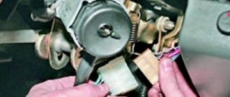
Features of repairing the VAZ 2109 switch
Repairing a switch most often comes down to replacing it. Fine-tuning the device is intended only to improve the efficiency of the system. If the device breaks down, the procedure for replacing it is as follows:
- de-energize the vehicle's electrical system, remove the main terminal from the battery;
- disconnect the brown wire from the negative terminal of the battery;
- Use a screwdriver to press out the spring bracket and disconnect the block with wires from the switch;
- unscrew the two radiator mounting nuts and remove the device together with the radiator;
- install a new switch with a radiator;
- connect the connector block;
- place the brown wire under the left nut;
- secure the switch to the VAZ 2109 with nuts;
- connect the battery.
How does a switch work?
Essentially, a switch is a simple signal amplifier. It can even be compared to a Darlington assembly, which is used in microcontroller technology to convert a weak signal from an output port to the required level. The basis of this assembly is field-effect transistors operating in switch mode. An operating voltage is applied to them, a signal is sent to the control terminal, which is amplified and removed from the collector.
The ignition switch has an almost similar operating scheme. Only the signal from the Hall sensor is used. It has three outputs - control, common, plus power. When a metal plate appears in the sensor area, a current is generated, which is supplied to the input of the switch. Next, the signal is amplified and supplied to the primary winding of the coil. The entire system is powered only after the ignition is turned on (after turning the key).
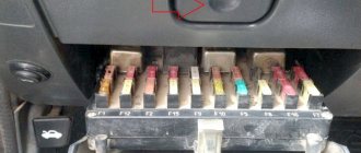
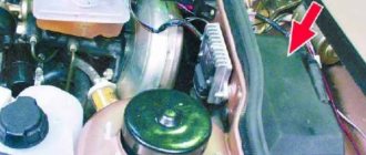
Relay and fuse diagram 2108
The relay and fuse box is located under the hood, in the compartment in front of the windshield on the left side.
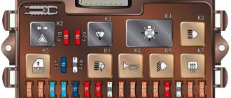
Fuse block 2114-3722010-18
K1-relay for turning on headlight cleaners VAZ 2108; K2-relay-breaker for direction indicators and hazard warning lights; K3 - windshield wiper relay; K4-relay for monitoring the health of lamps; K5-power window relay; K6 - relay for turning on sound signals; K7-relay for turning on the electric heating of the rear window; K8-relay for high beam headlights; K9-relay for low beam headlights; F1-F16 - fuses.
Fuse block 2114-3722010-60
K1 - Headlight wiper relay, K2 - Turn signal and hazard warning relay, K3 - Windshield wiper relay, K4 - Brake light and parking light relay, K5 - Power window relay, K6 - Horn relay , K7 - Relay for turning on the heated rear window, K8 - Relay for turning on the high beam headlights, K9 - Relay for turning on the low beam headlights, F1 - F16 - VAZ 2108 fuses, F1 - F20 - Spare fuses.
Basic Switch Elements
The switch circuit is quite simple, but making this unit yourself is pointless, since buying a ready-made version will be much easier. Installation must be carried out as competently as possible, otherwise the device will not operate correctly. In addition, when using transistors, you need to carefully select them according to their parameters, and for this you need to have high-quality measuring equipment. Unfortunately, for two identical semiconductors, the spread of characteristics can be very large. And this affects the operation of the device.
The VAZ switch, designated 76.3734, consists of one main element - the L497 controller. It is designed specifically for use in contactless ignition systems. The domestic analogue of this controller is KR1055HP2. Their parameters are almost identical, which allows you to use any of the controllers. In addition, this chip allows you to connect a tachometer located on the dashboard of the car. But you can also use a simpler circuit, which is an amplifier unit of two stages. True, the reliability of such a device is much lower.
Connecting the switch
Cases vary, and it is possible that you will have to change the wiring. Therefore, you will need to take into account the purpose of all pins on the switch plug. This will allow the connection to be made correctly, and there will be no risk of damaging it. The first pin of the switch is the output. In other words, the amplified signal is removed from it. It must be connected to the terminal of the “K” coil. The second contact is connected to ground - the negative of the battery.
All three wires from the Hall sensor go to the VAZ switch. Moreover, the signal wire is connected to the sixth terminal of the switch. The fifth is the power output (the voltage on it is stable 12 Volts). The third output of the switch is ground (minus power). The third is connected inside the block to the second. But between the fourth, which is supplied with power from the battery, and the fifth there is a constant resistance and a voltage stabilizer.
What signs indicate a faulty switch?
The most obvious sign of a faulty switch is the loss of the so-called spark, as well as interruptions in the operation of the engine, for example, it may begin to have difficulty starting and quickly stall even after warming up.
It is not recommended to immediately change the switch due to loss of spark, since such a malfunction is sometimes caused by other automotive components that fail:
- Hall Sensor;
- timing belt rupture;
- poor contact in the distributor;
- ignition coil failure. If a malfunction is detected in this particular element, then, according to experts, the coil needs to be replaced rather than wasting time on repairing it.
If diagnostics of the components described above confirm their serviceability, you will have to begin checking a more complex device called a switch.
How to check
There is nothing complicated in this procedure. The easiest way is to use a known-good node, since you can check the switch this way in literally a matter of minutes. But if there is none, and you need to determine exactly whether the fault is in the coil or in the switch, it is wiser to use other methods. You will need a simple incandescent lamp. If you don’t know where to get it, then unscrew it from the interior lamp or from the side lights.
Connect one terminal of the lamp to the negative of the battery. Connect the second one to pin “1” of the switch. This is the same pin from which the amplified signal is removed. If the lamp lights up, then the device is working properly. A more advanced testing method is carried out using an oscilloscope. On the screen you can see the magnitude and shape of the signal, and also compare it with the reference one.
Checking and replacing the device
When checking and repairing a car’s contactless ignition system, it is imperative to check the functionality of the switch. To test this device, you need to have a standard set of tools on hand. In addition, you will need a control light with a voltage of 12 V.
A full check of the element is carried out on a specialized stand, which allows not only to determine the presence of an impulse, but also its duration. Using a test lamp makes it possible to determine the presence of only a pulse when testing the device at home. To check the operation of the switch, you need to do the following operations.
- It is necessary to de-energize the vehicle's on-board network. This is done by disconnecting the negative terminal of the battery from the electrical circuit.
- Using an open-end wrench No. 8, terminal “K” is disconnected on the ignition coil, which has a red-brown wire connected to terminal “1” of the contact block of the switching device.
- The disconnected wire is connected to its terminal on the ignition coil through a light bulb, after which the negative terminal of the battery is connected to the on-board network. When the starter is turned on, the lamp should flash. The absence of blinking indicates that the switch is faulty.
When operating a car, in order to avoid failure of the switch, it is necessary to periodically clean the surface of the cooling radiator.
Ignition settings
When setting up the ignition, you will need to do the most important thing - install the shafts according to the marks so that the gas distribution functions synchronously with the operation of the piston group. This is the first thing you should do before you start adjusting the ignition. It is worth noting that there should not be any particular difficulties during setup, especially on VAZ 2108-21099 cars. The thing is that the ignition distributor on the engines of these machines can only be installed in one position. Moreover, the ignition switch does not undergo any settings during this procedure, since it does not have any.
The distributor body rotates around its axis to make more precise adjustments. And this turns out to be enough. To accurately set the torque, you can use a simple circuit that uses a simple LED as an indicator. The Hall sensor is disconnected from the system, and positive power is supplied to its negative terminal. An LED is switched on between “+” and the signal LED, and a 2 kOhm resistance is connected in series with it to reduce the voltage. But the plus of the Hall sensor is connected to ground. Now all that remains is to slowly rotate the distributor housing. The moment when the diode lights up will be the desired one.
Techno lovers site
Since an idea appeared on the Internet about the possibility of using the 3620.3734* switch instead of the standard Tavria 1102.3734/1103.3734, I decided to post an article on repairing them, along with the diagrams of these switches. The original article is here, but for some reason the developer of this web page posted the pictures separately from the article. It’s very inconvenient, I’ll translate it in human terms:
When the electronic ignition switch in your car fails, as a rule, you either buy a new one, since there is no way to check its functionality due to the lack of specialized service centers, or take it to local craftsmen who try it using the “scientific poke” method repair. Most operating instructions do not contain a description of the troubleshooting technique, so we provide a complete troubleshooting technique and circuit diagrams of the most common electronic ignition switches.
Ignition systems for gasoline engines of domestic passenger cars VAZ-2108, VAZ-2109, ZAZ-1102 contain an electronic switch. It is designed to generate current pulses in the circuit of the primary winding of the ignition coil.
In domestically produced electronic switches (series 3620.3734; 36.3734; 78.3734), the functions of the output current switch are performed by a powerful transistor, and the functions of controlling the parameters of current pulses (normalizing the duty cycle of triggering pulses, software regulation of the time of energy accumulation in the ignition coil, limiting the current level in its primary winding and amplitude of primary voltage pulses) is performed by a low-current electronic circuit, often in an integrated design.
The first domestic electronic switch with controlled parameters of ignition pulses (series 36.3734) was developed for the VAZ-2108 car. The switch used the K1401UD1 microcircuit, a powerful key transistor KT848A and other domestically produced elements.
The input information signal for the switch is the signal from the Hall sensor located on the ignition distributor shaft. Using this signal, the switch receives information about the number of engine revolutions and the position of its crankshaft. The switch is designed to work with a serial ignition coil 27.3705. The switch was a prototype for the development of subsequent series, which have several design and circuit design options. However, what domestic switches still have in common is a combined integrated-discrete assembly technology, which makes them repairable.
Modern domestic switches use specialized output key transistors of the types KT890A, KT898A1, BU931 (foreign) in several designs: TO-220, TO-3, unpackaged. Some switches, for example 78.3734 (Fig. 4), use a four-channel operational amplifier of the K1401UD2B type as a control chip.
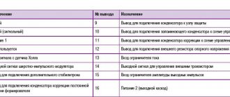
The switches also widely use the L497B control chip from SGS-TOMSON (domestic analogue of the P1055HP1). The block diagram and the recommended option for its inclusion are shown in Fig. 1, and the assignment of the pins is in table. 1.
Control chip L497B from SGS-TOMSON (domestic analogue of P1055ХП1). Block diagram and recommended option for its inclusion.
| Pin no. | Purpose | Pin no. | Purpose |
| 1 | General | 9 | Terminal for connecting the capacitor to the protection unit |
| 2 | General (signal) | 10 | Pin for connecting a storage capacitor to the delay control circuit |
| 3 | Meal 1 | 11 | Pin for connecting the correction capacitor to the delay control circuit |
| 4 | Not used | 12 | Pin for connecting an external voltage reference resistor |
| 5 | Hall sensor signal input | 13 | Current limiter input |
| 6 | Pulse Width Modulator Output | 14 | Output signal for driving an external transistor |
| 7 | Output for connecting an additional zener diode | 15 | Output pulse amplitude limiter input |
| 8 | Output for connecting the driver time constant correction capacitor | 16 | Power supply 2 (output stage) |
Before you begin troubleshooting and repairing the electronic switch, you should:
- check the integrity of the vehicle wiring, the reliability of the contact connections of the ignition system, the serviceability of the ignition system elements (spark plugs, ignition coil, Hall sensor, high voltage wires);
- check the serviceability of the car generator, as well as its integrated voltage regulator;
- check the supply of voltage from the on-board network (with the ignition switch on) to contact “P” of the Hall sensor connector.
The signs that indicate malfunctions of electronic switches, the most likely causes of these malfunctions and methods for eliminating them are summarized in table. 2.
conclusions
Many advantages are provided by such a simple unit in a contactless ignition system as a switch. This includes an increase in power, even if only slightly, a reduction in fuel consumption, and a significant improvement in the engine in terms of reliability. And most importantly, there is no need for constant monitoring and timely adjustment of the system. The modern driver does not want to repair a car, he needs a means of transportation. Moreover, it is reliable and will not let you down at the most crucial moment. Regardless of which switch is used in the BSZ, its efficiency is much higher than that of a contact breaker.
Microprocessor switch with automatic octane corrector “Astro” 962.3734
PURPOSE Microprocessor switch 962.3734 with automatic octane corrector (hereinafter referred to as MKAOC) provides sparking in contactless ignition systems of four-cylinder, four-stroke gasoline internal combustion engines. Installed on cars: VAZ-2105, -2106, -2107, -2108, -2109, -2110, -21213, -2130 and their modifications.
MKAOC allows you to: — automatically adjust the ignition timing depending on the quality of gasoline used, load and other factors, without driver intervention; — monitor the health of the Hall sensor and the switch control circuit; — set the initial ignition timing. Installed on carburetor cars equipped with an analog contactless ignition system.
DEVICE AND PRINCIPLE OF OPERATION MKAOC is built on a microcontroller using a broadband knock sensor. Processing signals coming from standard sensors and a knock sensor allows the system to automatically adjust the ignition timing depending on the quality of gasoline used, load and other factors, without driver intervention. Operates without a knock sensor like a regular switch.
ADVANTAGES OVER OTHER SWITCHES • Automatic adjustment of the ignition timing (IAF) • Diagnostics of faults • Allows you to set the initial ignition timing without special equipment • Reduced fuel consumption (with a working engine with an adjusted carburetor) • Increased engine life • Increased engine traction torque at low speeds • Improved acceleration dynamics • Easier engine starting (multi-spark mode) • Reduced engine noise (sharp reduction in detonation) • Quick shutdown of the ignition coil (0.5 sec.)
TECHNICAL CHARACTERISTICS • Supply voltage 8...16 V • Permissible crankshaft rotation speed 6000 rpm • SPD adjustment range 0...11° • SPD adjustment downwards when starting the engine 3° • SPD adjustment discreteness, per ignition stroke: - to the side decrease (during detonation) 1...2° - towards increase 0.1...0.2° • Switching current 7.5...8.5 A • Maximum current consumption 3 A • Ignition coil shutdown time 0.5 s. • Operating temperature range –40…+85 °C • Weight, no more than 200 g.
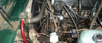
I installed it on a free technological hole with a ∅8 mm thread (thread pitch 1.25 mm) on the side of the oil dipstick near the 1st cylinder. Since my engine is well tuned, I didn't notice much of a difference, but I think it gets the job done.
I purchased this device for a long time, it is unknown for what purpose, now I have found where to put it.
kit contents
DD mounting location
switch