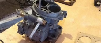
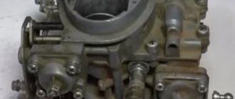
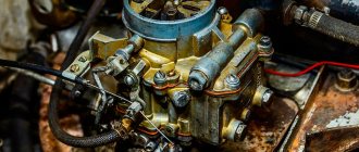
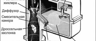
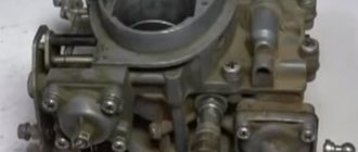
The carburetor has a balanced float chamber, a system for suctioning crankcase gases behind the throttle valve, and blocking the second chamber. The carburetor has two main metering systems of the first and second chambers, an idle system of the first chamber with a transition system, a transition system of the second chamber, a forced idle economizer, a power mode economizer, a mechanically driven diaphragm accelerator pump and a diaphragm starting device.
The carburetor consists of two body parts: body 33 and carburetor cover 13. An air damper 16 of the starting device is installed in the inlet neck of the first chamber. A lever 27 with two pins is rigidly mounted on the air damper axis, one of which has a return spring attached. The second pin fits into the shaped groove of the lever 26 for controlling the air damper. The adjusting screw 25 for slightly opening the throttle valve of the first chamber and the pin of the lever 40 for locking the second chamber rest on the outer edge of the lever 26.
The carburetor cover 13 contains a fuel supply needle shut-off valve 32, a float 38, a fuel filter 31, and a fuel supply pipe 14 to the float chamber. The trigger cover with diaphragm 18 assembled with the rod is attached to the boss of the cover 13. An electromagnetic shut-off valve 10 with an idle fuel jet is wrapped in the cover. Large diffusers are cast in the carburetor body 33 and small, easily removable diffusers are installed, cast integrally with the nozzles of the main metering systems. Housing 33 contains accelerator pump nozzles 17 with a ball valve, main air jets 15 and 28 with emulsion tubes 29 in emulsion wells, and an intake tube of the transition system with a fuel jet. The main fuel jets 36 are wrapped in the emulsion wells. An adjusting screw for the completeness of closing the throttle valve 34 of the second chamber, as well as an adjusting screw 20 for the amount of idle mixture with an electric drive for the limit switch of the forced idle economizer are installed in the bosses of the carburetor body. The idle mixture quality adjusting screw 24 is screwed into the housing.
The accelerator pump cover with the drive lever 4 assembled with the pump diaphragm 6 is attached to the casing boss 33, which forms the working cavity of the accelerator pump, with four screws. The power mode economizer cover with working diaphragm 9 is also attached to the housing with screws. A spring acts on the diaphragm. A fuel jet 7 and a power mode economizer valve are installed in the carburetor body under the diaphragm 9.
In the lower part of the housing 33, throttle valves 2 and 34 are installed on the axles. On the throttle valve axis of the first chamber there are installed: a throttle valve drive lever 39 with an adjusting screw 25 for slightly opening the valve and with a second chamber locking lever 40; lever 37 of the throttle valve drive of the second chamber; return spring and cam 5 of the accelerator pump. A throttle valve lever 35 is installed on the throttle valve axis of the second chamber.
Blocking the second chamber prevents the throttle valve of the second chamber from opening in any engine operating mode unless the air damper is fully open. The lock prevents the second mixing chamber from operating when the engine is not warmed up.
Selection of types of jets for Solex 21073 carburetor. Everything you need to know
It’s good if you know a carburetor mechanic. And if not? You can try to make the adjustment yourself, but for this procedure you need to know at least more information about the carburetor itself.
Selection of types of jets for the Colex 21073 carburetor
– one of the components of its configuration for the most reasonable further operation. And before replacing one with another, you need to fundamentally understand: why, and what kind of detail is this?
Therefore, we can say that it all starts with the fuel nozzle - its selection and settings. Afterwards, for the second time, you need to pick up an air one for it. Start strictly with the first camera until you have set it up; it is not recommended to work on the second one under any circumstances.
Rule:
We select the jets according to the engine volume. And before starting the setup, it’s best to find a factory Solex that matches the volume of the unit on your car, and rearrange (or install the same) jets from it.
Next you need to decide
, what do you want to get: economical slowness or costly acceleration. Depending on the decision, we also select a fuel mixture: to adjust the enrichment or leanness of the air-fuel mixture (a lean mixture will lead to gasoline savings, but will affect the acceleration dynamics of the car).
Engine 1.5 D
. carb - Solex 21073. In the first - TZh 115th, VZh - 155 ZD. In the second - TZh 115, VZh 135 ZC. XX - 41st. Gasoline AI 80. Consumption – highway 10, city 12.
In general, in addition to the selection of jets, there are a lot of useful and interesting nuances of setting up the Solex, so that it works correctly and is combined with the engine of your carburetor car.
You should always start by setting the levels in the chambers. They are installed manually according to the positions of the floats themselves, depending on the unit cover (everything is done using special templates). And in vain you think, like many gullible Solex users, that everything is already on display from the factory. To avoid overflow and stress on the needle, we make the appropriate adjustments by bending the float tongues.
After setting the levels, you can start idling. It depends on the position of the screws for the quality and quantity of the mixture (torsion should be performed with the suction removed).
Results
It goes without saying that there is no limit to improvement. Sometimes they can also turn into overkill: piercing, for example, a throttle valve, polishing a motor, welding exhaust pipes to a carburetor. But, as they say, it is immensely unhealthy. But such a fascinating procedure in its own way as choosing the types of jets for the Solex 21073 carburetor, for example, is an absolutely necessary thing for the correct setup of the unit and its full compatibility with the engine compartment. The result is a budget car that responds well to throttle.
Design, repair and operation
Over the 30 years of production of “classic” rear-wheel drive VAZs, their design, unlike their appearance, has remained virtually unchanged. Therefore, car owners are constantly trying to modernize them by introducing new components and groups of more modern foreign cars or VAZ cars. Many, for example, are dissatisfied with the performance of the Ozone or Weber carburetor, which does not provide good acceleration dynamics, smooth acceleration, low fuel consumption and low toxicity levels. At the same time, all this is at the mercy of their “younger brother” Solex. This is why many people replace their original carburetor with an approved “French” one.
The Dimitrovgrad Automotive Aggregate Plant (DAAZ), under license from the French company Solex, produces about a dozen modifications of Solex carburetors for engines with different displacements. This carburetor model was originally created for front-wheel drive VAZ models, since “Weber” and “Ozone” were installed on an engine located transversely in the engine compartment; in certain driving modes (during strong acceleration, in turn, on steep climbs), the fuel-air mixture was overestimated ... This occurs due to unwanted movements of the float in the float chamber. “Solexes” are free from this drawback, since their buoyancy chamber is two-sectional, that is, with paired floats that move in a plane perpendicular to the longitudinal axis of the car (and not parallel, as in “Ozone” and “Weber”). In addition to the “eight” and “nine”, in the mid-80s “Solex” began to be installed on other new front-wheel drive models: “Muscovites” AZLK-21412 (with the usual longitudinally mounted UZAM-331.10 engine) and “Tavria” ZAZ- 1102.
The Dimitrovgrad Automotive Aggregate Plant (DAAZ), under license from the French company Solex, produces about a dozen modifications of Solex carburetors for engines with different displacements. This carburetor model was originally created for front-wheel drive VAZ models, since “Weber” and “Ozone” were installed on an engine located transversely in the engine compartment; in certain driving modes (during strong acceleration, in turn, on steep climbs), the fuel-air mixture was overestimated ... This occurs due to unwanted movements of the float in the float chamber. “Solexes” are free from this drawback, since their buoyancy chamber is two-sectional, that is, with paired floats that move in a plane perpendicular to the longitudinal axis of the car (and not parallel, as in “Ozone” and “Weber”). In addition to the “eight” and “nine”, in the mid-80s “Solex” began to be installed on other new front-wheel drive models: “Muscovites” AZLK-21412 (with the usual longitudinally mounted UZAM-331.10 engine) and “Tavria” ZAZ- 1102.
Which Solex should you choose?
Dimitrovgrad carburetors of the Solex family differ from each other mainly in the geometric parameters of the jets, diffusers, emulsion tubes, as well as the profile of the starting system control lever. Despite these differences, any carburetor can be installed without negative consequences on all models for which they were intended at the creation stage: front-wheel drive VAZ-2108 and -2109, AZLK-21412, ZAZ-1102. There are modifications for the “classics” - VAZ-2104, -2105, -2107. It follows that the Solex, without altering the fasteners (frame geometry and position of the studs), can be easily installed on any rear-wheel drive Zhiguli engine. Although I note that the result of the modernization - engine characteristics - will depend on the initial choice. In any case, the engine will receive higher torque and the car will accelerate more smoothly. For economical driving, you should choose a modification for the Tavria - DAAZ-2181 (for a 1.1 liter engine). On the DAAZ-21073 (it has larger diameter diffusers), designed for an engine with a displacement of 1.7 liters, it is possible to achieve high acceleration dynamics and a high “maximum speed”, but this will significantly increase fuel consumption. Solex 2108 (1.3 l), 21083 (1.5 l), 21051-30 (1.3 l) are the “golden mean” - they provide decent acceleration dynamics and lower fuel consumption compared to ozone.
It is possible to install both a new (220 - 260 UAH) and a “used” (80 - 120 UAH) carburetor. In the latter case, the unit should be modified: rinsed, cleaned, blown out the channels, polished the speakers (with wire and GOI paste). It is also recommended to install new castings, gaskets and diaphragms manufactured by Dimitrovgrad auto repair kits often include castings with insufficient calibration dimensions). For efficient operation of the diffuser, it is recommended to remove all burrs and protrusions (casting defects) from its parts with a diamond file, which create additional air turbulence, which impairs the filling of the cylinders with a new charge
Important details:
All Solex carburetors, with the exception of modification 21073, have very thin holes that are very sensitive to any mechanical contaminants in the fuel. For this reason, fine filters should be changed in a timely manner, and for greater reliability it is better to install a filter from fuel injection systems. It is more expensive, but the intervals between carburetor maintenance will increase significantly (2-3 times).
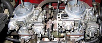
If you decide to install a Solex carburetor, then in addition to its cost, the estimate must include the costs (40-50 UAH) for the purchase of additional components (see Photo). The technology for installing Solex on a VAZ-Classic is presented in the diagram. We present the simplest method of modernization - without connecting the EPNH - a forced inactive economizer (we will talk about this in one of the following publications). According to experts, the EPHH system reduces fuel consumption by 5-10%, but often fails, and therefore generally reduces the reliability of the carburetor. To prevent the solenoid valve from cutting off the fuel supply in the absence of the EPPC unit, its plastic needle can be cut or pulled out of the housing. However, it is more advisable to connect the valve to an electrical circuit so that it opens the idle channel only when the ignition is turned on. This way, you can avoid the engine continuing to run after the ignition is turned off if you use low-quality gasoline or gasoline with a low lead content, which is a source of detonation, overheating and overheating.
When installing a carburetor from front-wheel drive VAZ modifications that have a fuel return line, the fuel return fitting can be connected with a plug or connected through a check valve to the fuel supply circuit to the fine filter. Following the advice of experts, we chose the second method of modernization, which eliminates overload of the carburetor valve mechanism and interruptions in its operation.
To get the most out of replacing this key fuel system element, it makes sense to upgrade your ignition system to a proximity ignition system. Solex carburetors are initially set to create a lean mixture. To ignite it effectively, it is necessary to create a more powerful spark discharge on the spark plug. This can only be ensured by a contactless ignition system, the coil of which produces a voltage of up to 25,000 V, and the gap between the electrodes on the spark plugs is 0.7-0.8 mm. Let me remind you that in a contact-transistor ignition system the indicated characteristics are 17000V and 0.5-0.6mm, respectively. The play in the contact system can be increased, but this will lead to accelerated failure of the bearing of the moving plate of the switch, its contacts and the capacitor.
After installing the carburetor and successfully starting the engine, be sure to contact a specialist for final adjustment of the unit for exhaust toxicity. Without this operation, in addition to increasing the toxicity of exhaust gases, fuel consumption and dynamics may deteriorate.
Preparation
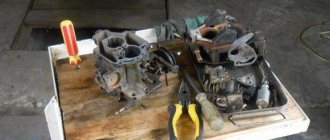
Well, now everything is in order, the first thing you need to do is get what is shown in the first photo. First of all, I will add for myself that you buy these things carefully, taking into account the following:
thin paronite gaskets should be specifically for the Solex carburetor (the holes for diffusers do not match the gaskets for Weber and Ozone), and in my opinion, instead of two identical gaskets, it is better to buy a gasket with two holes (between the carburetor and the getinax gasket) and an oval shape (between the gasket getinax and collector);
the “return” fuel line must be at least 80 cm long (otherwise it simply will not reach the fuel line in front of the fuel pump);
The Solex carburetor flap (popularly called a “helicopter”) may have to be cut approximately in the center between the holes, since it will not flatten on the carburetor (in my case there was no need to saw, but the photo clearly shows the sawn stage) in addition to do not saw the slides, try placing the carburetor on the studs, having first put it in place;
Well, one last thing: don’t skimp on clamps; for some time now I’ve only been using NORMA clamps, which cling to shit and don’t slip, even if they cost twice as much as regular ones.
Well, now the actual installation progress of this wonderful device ;)…
Mounting kit:
1. To prevent dirt from getting into the intake manifold and installed carburetor, first flush the engine compartment.
2. Disconnect the standard ozone carburetor drive rods and cables, as well as the heater hoses and fuel lines.
3. To remove the choke cable cover from the rear of the "suction" panel, pull out the spring clip.
4. Clean the manifold mounting surface thoroughly, avoiding any dirt getting into the engine.
5. Apply sealant to prevent air leakage (if there are small projectiles at the landing site).
6. Install the pads according to the “sandwich” pattern: thin-thick-thin. Thick padding provides thermal insulation.
7. For ease of installation, install the carburetor without the top cover so that the throttle valve drive is in front of the car.
8. Install the throttle valve connection on the cylinder head cover side.
9. To prevent the damper from getting stuck with the standard spring, it is best to install old plastic tips with developed seat sockets on the rods.
10. Pull out the choke cable on the cylinder head cover, adjust the length, cut the casing and connect it to the carburetor.
11. Install the carburetor top cover using a new gasket.
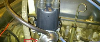
12. Connect the hoses of the heating system (from the cooling system) and the vacuum regulator of the ignition distributor to the carburetor tee.
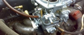
13. Cut out a tee in the fuel line to the fine filter and connect the carburetor return fuel line.
14. We turn on the check valve in the return pipe and connect it to the carburetor.
15. Using a standard return spring, we hook it to the axis of the old wing on the cylinder head cover.
16. During the break-in period, install an additional spring to operate the new throttle valve rod ball heads.
17. Connect the EPHX solenoid valve to the positive terminal of the light relay.
18. Install the air filter housing, filter element and cover, connecting the crankcase drain pipes to them.
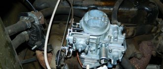
From my impressions: the accelerator pedal has become much more sensitive than the Weber, there are practically no failures in any mode of carburetor operation. In principle, the conclusion is this: if you rarely drive with the second chamber open, then the fuel savings will be about 1 liter. If you contact the police, there will be no savings, but the dynamics of the car will become noticeably higher.
Recommendations for setting up and fine-tuning Solex
The standard carburetor is fully functional and tuned, but the car's dynamics leave much to be desired. The easiest way to solve this problem is to install a DAAZ 21073 carburetor. Installation without modification is possible, but the first chamber prepares a lean mixture as standard. For this reason, when the first chamber is running (when the throttle valve of the second chamber is closed), the engine does not provide enough thrust for intense acceleration. The car will slowly accelerate through the first chamber and sharply increase the acceleration speed when the second chamber is opened. The latter can create certain difficulties in managing traction on surfaces with low friction coefficients. The fact is that when the second chamber is opened, the car literally jumps forward. True, there is a flip side to the coin - fuel efficiency. This is the main feature of the 21073 carburetor.
To fully realize the benefits of increasing the diameter of the main diffuser of the first chamber will help to increase the flow rate of the main fuel nozzle (hereinafter referred to as the fuel nozzle) of the first chamber. The first option is a compromise between efficiency and traction force, replacing the GTZ from 107.5 to 110. The intensity of acceleration in the first chamber will increase, but only slightly. The most optimal for the first chamber is GTZh 115. It is possible to install GTZh 117.5, but fuel consumption will increase slightly. It should be noted that installing a gas turbine engine with an efficiency of more than 117.5 leads to excessive enrichment of the mixture and, as a result, to an increase in fuel consumption and (in most cases) to a deterioration in acceleration dynamics.
Compensating jets (hereinafter referred to as QL) are also air jets; they affect the composition of the mixture when the vacuum in the main carburetor diffusers increases, which occurs with increasing engine speed. Up to medium speed (
2500 rpm) have a slight effect on the mixture composition, but with increasing speed their influence on the mixture composition increases. The arithmetic is simple, the lower the QL flow rate, the more the mixture becomes richer as the engine speed increases. Therefore, when using GTZh with a yield of 107.5 and 110, it is advisable to slightly enrich the mixture using CL with a low yield: 145, 150, 155. When using GTZ 115, you can use both 155 and 165 CL. 117.5 is better to put QOL 165.
All of the above applied to the jets of the first chamber of the DAAZ 21073 carburetor. With the second chamber everything is a little simpler. You can leave everything as is (GTZh 115, KZh 135) or install GTZh 120. The latter will slightly affect fuel consumption, but will improve the acceleration dynamics of the car. It should also be noted that it is undesirable to set the maximum GTZ in both chambers. The best effect can be achieved with the maximum permissible enrichment of one carburetor chamber. For example, with a moderate GTZ in the first chamber (107.5 or 110), it makes sense to enrich the second chamber by installing a GTZ 120. With this ratio, the first chamber will be moderately economical with acceptable acceleration dynamics, and the second chamber will compensate for the lean mixture when both throttles are fully open.
Carburetor DAAZ 21073 on classic VAZ engines
Previously, the problems of installing the DAAZ 21073 carburetor on engines of the 2108 family were discussed. When installing this carburetor on engines of rear-wheel drive VAZ models, the following features should be taken into account. The KZH of the first chamber does not need to be changed, since the emulsion tube ZD, made in combination with KZH 150, is designed specifically for the operation of a carburetor on a longitudinally mounted engine. The optimal GTZ for the first chamber are 107.5 and 110. When installing GTZ 115 in the first chamber, fuel consumption will significantly increase and acceleration dynamics will deteriorate due to excessive enrichment of the mixture.
Some operating features of DAAZ 21073
There are a number of other characteristics associated with the operation of Solex carburetors. Below we will try to describe some of them.
Carburetor classifications
- Oka - for rear-wheel drive VAZ models: 2101, 21011, 21063 with volumes from 1.2 to 1.3 liters;
- Ozone - for the classic modification of VAZ 2107, 21043, 21053, 21074. Power unit volumes are from 1.5 to 1.6 liters. The design already includes an idle economizer;
- Solex is a universal version of the carburetor for VAZs without a microswitch and economizer. Installed on engines with volumes of 1.5 and 1.6 liters. For the most part, modern VAZ models of front-wheel drive and all-wheel drive are equipped with them.
It is also customary to distinguish mechanisms based on the principle of supplying the fuel mixture to the cylinder chambers:
The last two types are becoming less and less common, due to the obsolescence of the design and inefficiency.
His Majesty diffuser
As you can see, the diffuser occupies not the last place in this hierarchy, and here’s why. The main problem with Solex DAAZ 21083 is that the standard mixture is too lean. The engineers deliberately took this step in order to strangle the engine in favor of efficiency, depriving it of its dynamic potential. But even without resorting to complex and subtle calculations, it is clear that first of all it is necessary to eliminate aerodynamic errors, which are full of any DAAZ carburetor.
After the diffusers are brought into human form, the filling of the cylinder with the working mixture is significantly improved, and as a result, the output from the engine, even after such an insignificant alteration at first glance, is visible even to the eye. Now it makes sense to think about increasing the filling of the combustion chamber. Standard diffusers on 21083 have diameters of 21x23 mm of the primary and secondary chambers, respectively. Usually the dimensions are adjusted to 24 mm, so the motor will not be pinched at least by air.
Now you can increase the diameters of the fuel jets. “Can” does not mean necessary, and if fuel economy is more important, then the jets are best left alone. Even after replacing them with jets of increased diameter, the car will not turn into a Maserati, but fuel consumption will definitely increase. If this doesn’t scare you, then change the standard jets to 107.5 and 115, and the air jets to 155 and 135 in the primary and secondary chambers, respectively. If you are not satisfied with the result, you can always install the standard jets in place.
Carburetor design
Regardless of the model and brand of the manufacturer, the operating principle of each mechanism is as follows. Creation of a combustible mixture from dosed portions of oxygen and gasoline, uniform distribution across the combustion chambers in each engine cylinder.
Main components:
- top cover with transition channels for fuel and air, strainer, connecting fittings;
- lower base, consisting of throttle valves, float chamber, econostat, transition channels, crankcase gas exhaust, idle speed control unit.
For reference:
- the throttle valves are controlled mechanically from the accelerator pedal;
- The top cover is equipped with a special locking device to prevent the chambers from overflowing with the fuel mixture. In the main compartment of the chamber there is an air damper, which serves as an auxiliary element when starting a “cold” engine until it warms up to a minimum temperature of 40℃;
- main fuel metering system: a structurally complex mechanism consisting of four jets and channels of transition systems. Moreover, each chamber consists of one air and fuel nozzle. The marking index of the first is 150, the second is 112. It is important to observe the indicated dimensions, since the amount of fuel consumption and the dynamic acceleration of the car directly depend on this;
- idle system: ensures that the power unit operates at idle speed. Main components: jets, adjusting screws, economizer, valve, membrane mechanism;
- transition system: ensures smooth operation and increased speed when opening the throttle valve in the secondary chamber. Consists of two types of jets: fuel and air;
- pump - accelerator: responsible for smooth operation, preventing failures during acceleration, including sharp pressing of the accelerator pedal. Components: valve mechanism, membrane, fuel atomizer.
Operating principle
Solex carburetor float chamber ventilation system
Solex 21073 works as follows. Gasoline will enter the float chamber using the inlet fitting - the fuel also passes through the filter mesh, where it is cleaned, and goes through the needle valve. The chamber with the float is two-sectional, and the sections are connected to each other. They will contain the same amount of gasoline. This design makes it possible to significantly reduce the effect of body tilt on the fuel level in this chamber.
This ensures more stable engine operation. As the chamber fills, the float, pressing part of the needle valve, blocks the access of fuel to the chamber. This maintains a constant level of gasoline in the mechanism. Next, from the float chamber, gasoline flows through the jets into the mixing wells. Air enters these same wells through special holes in the emulsion tubes or air jets. Next, gasoline and air are mixed in them. As a result, a fuel mixture is formed. It will get into the small as well as large diffusers of the device. This is the main dosing chamber. Depending on the operating mode of the engine, certain mechanisms and systems can be started in the carburetor. When the owner tries to start the engine “cold” in order to enrich the fuel mixture, the starting device comes into play. The driver starts it from the passenger compartment - this is a choke.
When the handle is pulled out to its maximum, the air damper of the first chamber is completely closed. At the same time, the throttle valve in the first chamber opens to the distance of the starting gap. It is adjusted using the adjusting screw on the Solex carburetor. Adjusting the gap will allow you to adjust the idle speed.
Main signs of carburetor malfunction
- passive dynamics of acceleration of a technical device, a feeling of some kind of ballast preventing free movement;
- starting the power unit is difficult, regardless of the actual ambient temperature and the degree of warming up of the engine itself;
- when starting up there is a prolonged sneezing;
- the accelerator pedal is uninformative; when pressed, dips and jerks are frequent;
- fuel consumption has unreasonably increased;
- speed fluctuates during idling;
- distinct streaks of gasoline are visible on the body part;
- The fine fuel filter contains foreign particles, rust, waste, and lint. Of course, provided that the owner has a purifier installed in the fuel supply system.
Equipment location and dismantling
The standard fuel mixer is installed on the exhaust manifold platform using four studs in the engine compartment. It is recommended to carry out prophylaxis in the removed state. The design contains many small parts and mechanisms that require cleaning and diagnostics. Of course, if the breakdown is obvious and insignificant, then there is no need to dismantle the equipment at all. The final decision is made by the repairman. After all, this directly proportionally affects the final cost of the work.
To remove the carburetor from its standard seat, you must:
- Unscrew the air filter cover on the right side of the engine, remove the cleaner itself and its housing part. Having previously unscrewed the four nuts to “8”. Some motorists independently modify the mechanism to accommodate long “10” bolts for ease of fixation;
- disconnect the crankcase exhaust pipes, vacuum hose, fuel supply pipe, return channel. Since there are gasoline residues in the pipes, you need to get a rag to remove the consequences of the leak.
Note to the driver: it is strictly forbidden to carry out repair work on a “hot” engine, as there is a high probability of ignition. Ignoring these recommendations leads to undesirable consequences. Woe - craftsmen often get burned.
- When the body part of the “mixer” is completely freed from third-party mechanisms, it is necessary to release the fastening bolts of the top cover using a Phillips-head screwdriver. Just five;
This completes the dismantling of the upper half of the cover. To carry out a full diagnosis/repair, it is necessary to unscrew the second - lower part. The landing platform is mounted on four studs with nuts.
When removing the carburetor from its original place, you need to be extremely careful. The manifold outlet is open and a foreign object may get inside that should not be there. This can lead to the inoperability of the entire unit.
Replacement in every detail
Adjusting screws for the Solex carburetor 2108
Having selected the Solex carburetor jets by numbers, you can begin to replace them; unlike boring, it is quite possible to carry out this operation yourself at home. By the way, the reason is not always an incorrectly selected element; very often during operation, these parts wear out and become clogged, which leads to a change in the diameter and composition of the mixture with all the ensuing consequences. In addition, car owners in this way increase the power of their “iron horse” or, conversely, reduce gasoline consumption. In general, replacing jets is quite suitable in the category of vehicle tuning.
To remove the Solex jets, you will have to dismantle the engine and, of course, disassemble it. Before removing the power unit, be sure to disconnect the negative cable from the battery, and then remove the air filter housing. Prepare a clean rag and a solvent, such as white spirit, in advance to clean the surface of the motor from dirt. Now you need to find the place where the drive cable is attached to the air damper and slightly loosen the screw securing these parts. Do the same with the bolt securing the cable sheath. An open-end wrench is perfect for this purpose. After disconnecting the cable from the carburetor, remove the crankcase gas supply hose from the pipe.
Removing jets from Solex
To disconnect the fuel hose from the fitting, in addition to a wrench, you will also need a Phillips screwdriver. First, loosen the fastening clamp, then remove the hose and use an M8 bolt to plug the hole in the latter. It is necessary to remove the vacuum regulator hose. The wire terminal is also disconnected from the solenoid valve terminal. We take a flat-head screwdriver and use it to press out the end of the throttle linkage, and then remove it. Now it is possible to remove the return spring.
To remove the carburetor you need to prepare a spanner and open-end wrench set to “13”. The first to unscrew are 3 nuts, through which the part is attached to the inlet pipeline, and the second is the fastening nut. Take this opportunity to inspect the carburetor gasket; perhaps it could use replacement. If the unit will be removed for a long time, be sure to plug the inlet pipe with a rag. To replace the jets in the carburetor, it remains to remove the cover from it. Take a flathead screwdriver and unscrew these parts. First we remove the fuel jets, then the air jets. In the rings of the last parts you will find emulsion tubes; to pull them out, you should pry them off with a file.
Replacing the carburetor gasket
The main fuel element of the secondary chamber is designated by the letter “A”, and the primary one by “B”. Then we proceed to removing the air jets, marked “B” and “D” for the secondary and primary chambers, respectively.
Replacement should not be done blindly. Visually assess the condition of the jets. The presence of marks, scratches and irregularities on their inner surface is unacceptable, since these defects reduce throughput. Contamination of parts with resins also has a negative impact. Before installing new jets, it is advisable to check them on a special stand, so you can see how well the specified throughput of the elements corresponds to real indicators.
Installation of new Solex parts
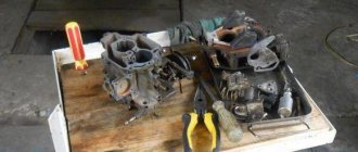
If you have already started disassembling the carburetor, then it would be a good idea to study the condition of its other parts; perhaps replacing the jets is not the only need for this unit. We unscrew the accelerator pump screw and remove the latter along with the valve and o-rings. Then we remove the rings and diffusers of both chambers from their original location. To remove the channel from the accelerator pump, you need to unscrew the fixing screw.
Next, remove the fuel nozzle along with the housing and take it out. You can dismantle the diaphragm after you open its cover and remove the spring. Having unscrewed the bolted connections, we disconnect the carburetor body and the throttle valve. Now you have access to the thermal insulation element and cardboard spacers. Remove the cover along with the adjusting screw, then remove the latter with the sealing ring. All parts with defects must be replaced; the remaining parts are thoroughly washed in a special product. We blow out the jets and other holes with compressed air. Reassemble in reverse order.
Diagnostics and complete analysis
The main goal of visual diagnostics is to identify visible, obvious defects in order to fix them and subsequently eliminate them. Before starting complete dismantling, it is necessary to prepare: an empty container for storing small parts, bolts, nuts, and other elements, a repair kit for asbestos gaskets. If the degree of wear of a part exceeds the permissible threshold, then it must be immediately replaced with a new one.
Stages of full analysis:
- in the lower part of the carburetor, the fuel and air jets are unscrewed alternately from the fuel chamber;
- The emulsion tubes inside each chamber are removed using a self-tapping screw, so convenient and practical. Some craftsmen use side cutters or tweezers. Everyone chooses “for themselves”;
- in the side of the body, unscrew the adapter nozzle of the second chamber;
- similar procedure with the idle screw;
- the lowest platform is the carburetor throttle mechanism, which is also unscrewed with a flat-tip screwdriver. For ease of clamping and to prevent oxygen leakage, the standard bolts are replaced with studs and nuts set to “8”;
- in the side part, the accelerator pump membrane is removed along with the lever and housing elements;
- the screw of the transition system of the first chamber is unscrewed;
- The economizer of the throttle assembly is removed from the top cover.
The full analysis is over.
Main dosing chamber - operating principle
During engine operation, the cylinders create a vacuum, which draws air from the air filter and supplies it to the diffusers - these are the main metering systems. After this, all the oxygen leaves through the cross-section of the damper of the first chamber and the jets of the Solex 21073 carburetor. Thanks to the throttle jets of the second chamber and the reduced diameter of the diffuser of the first chamber, the air flow speed increases, and in the spray zone it reaches maximum values.
Subsequently, after passing through the air jet of the throttle valve of the first chamber, the air is mixed with fuel and sucked into the channels of the intake manifold, which distributes the mass of the fuel mixture among the engine cylinders. To increase efficiency, distribution occurs in those cylinders where the intake valve is open and there is the required vacuum. This principle of operation ensures a reduction in fuel consumption and the elimination of contamination of the timing belt.
Completion of diagnostics. Cleaning. Washing. Blowing
Final inspection of all parts and components. Detection of defects, damage, replacement with new ones from the repair kit.
The stage of washing and cleaning begins. For convenience, you can use special chemicals and aerosol cans. If you can’t purchase it, pour a little gasoline or kerosene into the container, this will be quite enough. All components are thoroughly washed, the cavities are cleaned of foreign debris, carbon deposits, and metal oxides. Cleaning proceeds to the drying stage and the beginning of assembly.
Be sure to blow through the following elements:
- idle jet;
- fuel nozzle channels of the first and second chambers;
- transition system channels;
- selection of crankcase gases;
- seat for the emulsion pipe;
- secondary chamber opening mechanism;
- trigger channel;
- accelerator pump mechanism.
During assembly, we check the clearances of the float chamber. The float should close at 6.3 mm. An increase or decrease in this indicator indicates level violations. This is when we are talking about this type of carburetor device. Before landing in a regular place, be sure to replace the asbestos gasket of the exhaust manifold with a new one. It is not recommended to install the old one back, since the exhaust site is already actually present, which means that the tightness and tightness of the fit are not guaranteed.
Folk method of adjusting the fuel level in the chambers:
The design of the carburetor provides for a protrusion inward at an angle of 45 degrees. Ideally, half of the above protrusion should be covered with gasoline. The desired level is achieved by pressing the tongue at the end of the float.
This is interesting: Emergency brake fluid change
The fastening nuts are tightened with a force of no more than 2.5 kg; exceeding this threshold leads to the so-called “licking” of the thread. Even though it has a fine pitch, especially for strong force, it is still susceptible to deformation.
Float mechanism
The Solex 21073 carburetor, installed on the Niva, has a float chamber of two sections. They are located on both sides of the main cameras of the device. The system consists of two ebonite floats, which are mounted on a lever.
The latter swings on an axis pressed into the bosses of the device cover. There is a tongue on the bracket. The element presses the needle valve needle through a special ball. The float mechanism serves to adjust the level of fuel required for normal operation of the carburetor. The needle valve is a non-separable type. It is not being repaired. The valve body is mounted on a thread in the carburetor cap. The ball protects the needle from shock when the machine moves. If the chamber is empty (for example, if the driver is using LPG), then the floats will knock.
Equipment adjustment
Before adjusting the carburetor, you must set the ignition to make sure the system is in full working order. It often happens that it is the incorrect operation of the unit that causes many breakdowns.
So, final modification of the carburetor is possible when the ignition is normal, the engine is warmed up to the minimum permissible temperature of 40 degrees, the high-voltage wires and braids are intact and in good working order.
- turn the mixture quality screw counterclockwise until the power unit reaches maximum speed;
- We also add the mixture quantity screw until the engine reaches the maximum speed mark;
- Now we are fine-tuning the quality of the mixture, but at the same time keeping the speed indicator at no more than 800 - 850 rpm.
This completes the idle speed adjustment. Experienced craftsmen can determine the speed by ear.
The next stage: adjusting the dampers and their drive.
Idle system
This unit is necessary in order to supply the combustion chambers with a combustible mixture at the lowest speeds. Thanks to this system, the power unit will not stall when there is no load. Fuel will enter the system through the main jet into the first chamber. Through the XX jet, where it is then mixed with oxygen, the fuel enters the system through the air valve. This mechanism allows you to ensure stable engine operation at idle speed without load.
Next, the combustible mixture will enter the first chamber through a special channel located under the throttle valve. The fuel mechanism leading to the XX exhaust port is closed with a quality screw. This is an adjusting screw that can be used to adjust and change the characteristics of the carburetor. The operation of the engine in idle mode on the Solex 21073 mechanism is also adjusted with this element. Due to it, the gap value of the throttle valve of the first chamber in XX mode is determined.
Air damper
A malfunction of this section of the system will lead to a systematic loss of speed, and the engine will stall for no reason. To adjust, you will need a flat-tip screwdriver and an “8” open-end wrench. We push the suction rod all the way. Unscrew the rod clamp bolt as much as possible, insert the spring, and tighten the screw. We test equipment for performance.
The air damper drive must be adjusted with a partner. For convenience, you will need an open-end wrench set to “8”, a lighting fixture, and a caliper. We turn the choke all the way, the accelerator pedal also goes to the floor. At the same time, the throttle valve must be fully open. When the accelerator pedal is fully released, the flap completely closes the primary chamber. There should be no gaps at all. The rod length does not exceed 80 mm.
Some tips and tricks
When carrying out various types of preventative work on the carburetor, you should always observe the markings of the fuel and air nozzles. For the former it is 112, for the latter 150. If the positions do not match, the owner will immediately feel a decrease in acceleration dynamics and an increase in fuel consumption, which are not justified in any way. A narrowing of the throughput channel leads to a lean mixture; it, as well as enrichment, also negatively affects the performance of the machine as a whole.
This concludes the discussion of the topic. Despite the complexity of the mechanism's design, it can be repaired on your own. If you are still in doubt, read the recommendations again and successfully complete the repair. Now you know exactly what to do if your car stalls at idle.
