Symptoms of malfunction, diagnosis and replacement of the crankshaft position sensor
The operation of a car engine depends on the performance and condition of many different actuators and controllers. The electronic control unit, regulating the main parameters of the engine, is based on the readings of various regulators. One of these is DPKV. What signs of malfunction are inherent in the crankshaft sensor, where the device is located and how to diagnose it - find out from this article.
Existing types of sensors
DPKV are of three types according to the principle of action:
- Magnetic induction. They work on the basis of a magnetic field - the Hall effect. As soon as an empty section of the flywheel without teeth passes in front of the DPKV, a constant voltage appears and is supplied to the electronic control unit. As a rule, the supply voltage is 5V, but in older sensors it is 12V.
- Optical. The operating principle is based on the reception of light through the teeth of a synchronizing disk. When the light goes out for a certain time, the ECU receives a signal about a certain position of the crankshaft and then issues a command.
- Inductive. Inside there is a permanent magnet, a rod with an induction winding (coil), which reacts to the electromagnetic field. If these parameters are changed, a mark is fixed showing the specific position of the pulley on the shaft. The principle of operation is that a magnet creates a magnetic field, a driving disk with teeth changes this field, an alternating magnetic field induces an EMF in the coil in the form of a sine wave (analog signal), which is converted into a digital signal in the ECU.
The inductive type DPKV is considered the most common and is installed on all modern cars with an injector. In addition to the position of the crankshaft, it determines the rotation speed and is more functional.
Characteristics of DPKV
What is DPKV, what are the symptoms of a malfunctioning crankshaft sensor, and how to remove and replace the controller if a problem is detected? First, let's look at the basic questions regarding location and principle of operation.
Location, functions and operating principle
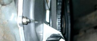
Before you check the position sensor and change the device, you need to find out where it is located. The installation location on most vehicles is inconvenient, since if replacement is necessary, it will be difficult for the car owner to reach it. The device is located on a special bracket, next to the drive pulley of the generator device.
Structurally, this part consists of the following elements:
- a sensitive component, which is a magnetized metal core;
- sensor connector used to connect to the machine’s on-board network;
- the body is usually cylindrical, made of plastic or aluminum;
- base with a flange, as well as a technological hole for fixing;
- wire with enamel insulation.
In order for the device to be more reliable and not quickly fail, the winding of the device is sealed using a special thermoactive polymer resin. As you know, the crankshaft disk has 58 teeth, which are located in a circle, the distance between them is 6 degrees. There is a special place on the disk for two teeth, this is used to determine the initial position of the crankshaft, which allows the generation of synchronization signals.
How does the crankshaft position sensor work? When the disk is rotated, the teeth act on the DPKV, changing its magnetic field, resulting in the formation of pulses. From the DPKV, the signal is transmitted to the electronic control unit, thus warning it about the frequency and position of the shaft. This is what is considered the basis for calculating the timing, according to which the ECU adjusts the ignition, as well as the operation of the fuel injectors.
If the DPKV transmits incorrect signals, the system will disrupt the cyclic operation of the injectors and ignition. Accordingly, this can ultimately lead to incorrect operation of the power unit, as well as its complete stop and the inability to operate the car.
Photo gallery “Types of DPKV”
Working principle of the synchronization sensor
For stable operation of the engine, the DPKV working process occurs according to the following principle:
- The crankshaft has a special gear (reference disk) with two missing teeth - start and zero.
- When the crankshaft rotates, the teeth, passing through the magnetic field of the DPKV, change it - as a result, pulses are formed in the device, the data of which is transmitted to the control unit;
- When a gear with missing teeth passes past the sensor, the nature of the pulses changes, and the unit determines the initial position of the crankshaft;
- Based on counting the received pulses, the computer determines the position of the crankshaft in a certain period of time:
- After processing the information, the ECU sends signals to the appropriate vehicle systems, and their operation is adjusted.
As a result, stable operation of the car engine is ensured.
Video: Operating principle and what the crankshaft position sensor is responsible for
Possible faults
The crankshaft position sensor should be replaced if damage is detected.
There are several ways to determine a breakdown, but first we suggest you learn about the symptoms that will help determine that the DPKV is faulty:
- Unstable operation of the power unit. When coasting, at neutral speed, engine speed can increase sharply and drop just as sharply. In addition, the car may stall for no reason, for example, while standing at a traffic light or going down a hill in neutral gear.
- A decrease in engine power, and the drop in speed can be felt even without a tachometer. The motor can periodically restore its performance, but not for long.
- When the engine was running, detonation appeared - the knocking of “fingers” or hydraulic compensators. This symptom is especially evident when driving uphill or when driving at low speeds.
- The spark is gone. The spark may disappear and then appear again.
- One of the most unpleasant signs for a car owner is the inability to start the car engine. Also, starting the engine may be difficult.
- The dynamics of the car as a whole have deteriorated (the author of the video is the Avtoelektrika HF channel).
Naturally, most of the above symptoms may indicate other problems in the operation of the power unit. The cause of such signs may be spark plugs, distributor, high-voltage wires, clogging of the fuel filter or its failure. Therefore, in order to make sure that this controller is faulty, you need to know how to check the crankshaft position sensor, we will discuss this below.
Methods of testing for functionality
Checking the crankshaft sensor begins with a visual diagnosis of the device. Check the condition of the case - there should be no signs of damage on it, the core should be intact, as well as the connector and contacts installed in it. If there are traces of dirt on the DPKV contacts, they should be removed by cleaning, for example, you can use alcohol or gasoline. For diagnostics, you must remove the sensor - when dismantling, check the distance between the synchronization disk, as well as the core of the device, this distance should be no more than 1.5 mm (video author - Ramil Abdullin).
If the visual check does not produce results, you can ring the device; for this you will need an ohmmeter. If the DPKV is working properly, then the test results should show about 550-750 Ohms, but before diagnosing, check this parameter in the service book. If the obtained values are outside the acceptable range, this indicates a failure of the controller; accordingly, it will need to be replaced. There is another diagnostic method.
Before checking the crankshaft sensor with a tester, you will need:
- voltmeter, it is better if it is digital;
- megohmmeter;
- device for measuring inductance;
- network transformer.
It is advisable that the diagnosis of DPKV be carried out in a room with a temperature of 20-25 degrees. The resistance level should be checked using an ohmmeter, as we described above. To measure inductance you will need a meter, the inductance should be around 200-400 MHz. Then, using a megohmmeter, the resistance of the insulating layer is measured; at a voltage level of about 500 volts, this parameter should be no more than 20 mOhm. If during diagnostics an unexpected magnetization of the synchronizing shaft occurs, the demagnetization process can be carried out using a network transformer (the author of the video is the VMazute channel).
Check on the way
Sometimes breakdowns happen unexpectedly, in the field, on the highway, and so on, where you don’t have a multimeter at hand, then a light bulb from any car lamp, for example, an interior lamp, will help you out:
And so you need an LED light bulb with two wires, which you, after removing the sensor, connect to it.
You act with an iron object as I already described a little higher.
If the crankshaft sensor is working properly, the diode will flicker.
Thank you my readers, now you can independently diagnose such malfunctions and not get confused, see you soon on the sidelines of the blog with new articles, subscribe to my updates on the blog, who has not done so yet, I wish you success in the repair, and that the repair is needed as much as possible less often!
Recommend my blog to your friends on websites, many thanks in advance. Goodbye.
Did you like the article? Share with friends:You may also be interested
What is considered normal engine oil consumption? Hello everyone, it's me again, with useful information about the permissible engine oil consumption
What is engine boost? Hello again everyone, today I’ll tell you about boosting the engine, what it is, why it’s done, and Sections
- Auto documents
- Automotive vitality
- Car devices Engine
- Body
- Suspension and steering
- Salon
- Fuel system
- Brake system
- Transmission
- Tires and wheels
- Electrical equipment
Subscribe By clicking the button, I agree to the newsletter and accept the privacy policy
- Car devices
- Auto documents
- Violation and fines
- Car brands
header>header>
Instructions for replacing the controller
Replacing the crankshaft sensor is carried out as follows:
- First of all, you need to turn off the ignition.
- Then open the hood and find the location where the DPKV is installed. The wiring connector should be disconnected from the controller.
- Using a wrench, usually a 10mm wrench, you need to unscrew the screw that secures the controller.
- Before dismantling the device, it is necessary to make appropriate marks where it is located. After this, the device must be removed.
- Then a new controller is installed taking into account the marks. The device is connected to the on-board network; a connector is installed for this purpose. Now start the engine and check the operation of the device; if everything is normal, then the replacement can be considered successfully completed.
We carry out inspections right in the garage
If the engine in the car has stalled, you won’t be able to get away, and even with a faulty engine, going anywhere is a very risky business; you simply won’t get there, so let’s start checking on the spot. First, open the hood and perform the following actions:
- We thoroughly clean the sensor body with a rag soaked in solvent, gasoline, turpentine, or other degreaser. We especially carefully wipe the end on the side of the toothed pulley.
- We check the fastening - suddenly it has become loose, a slightly loosened screw on the sensor allows it to move away from the teeth, the gap between the sensor and the teeth has increased, and the impulse has weakened accordingly.
- We clean the contacts in the connector from oxidation (with a thin screwdriver or an awl).
- We check the wiring so that it is not melted or broken.
- We try to start the engine, is the problem still there? If it disappears, you can go.
- When all the measures I described above did not help, a replacement remains.
Purpose and location of the crankshaft position sensor in the engine
The crankshaft position sensor (CPS, synchronization sensor, reference sensor) is a component of the electronic engine control system; a sensor that monitors the operating characteristics of the crankshaft (position, rotation speed) and ensures the functioning of the main systems of the power unit (ignition, power, gas distribution and others).
Modern internal combustion engines of all types are for the most part equipped with electronic control systems, which completely take care of ensuring the functioning of the unit in all modes. The most important place in such systems is occupied by sensors - special devices that monitor certain characteristics of the motor and transmit data to the electronic control unit (ECU). Some sensors are critical to the operation of the power unit, including the crankshaft position sensor.
DPKV measures one parameter - the position of the crankshaft at each moment of time. Based on the data obtained, the shaft rotation speed and its angular velocity are determined. Receiving this information, the ECU solves a wide range of problems:
- Determination of the moment of passing TDC (or BDC) of the pistons of the first and/or fourth cylinders;
- Control of the fuel injection system - determination of the injection moment and duration of operation of the injectors;
- Ignition system control - determining the ignition timing in each cylinder;
- Control of variable valve timing system;
- Control of the operation of components of the fuel vapor recovery system;
- Monitoring and correction of the operation of other engine-related systems.
Thus, DPKV ensures the normal functioning of the power unit, completely determining the operation of its two main systems - ignition (only in gasoline engines) and fuel injection (in injectors and diesel engines). The sensor also turned out to be convenient for controlling other motor systems, the operation of which is directly or indirectly synchronized with the position and speed of the shaft. A faulty sensor can completely disrupt engine operation, so it must be replaced. But before buying a new DPKV, you need to understand the types of these devices, their design and operation.
Types, design and principle of operation of DPKV
Regardless of type and design, crankshaft position sensors consist of two parts:
- Position sensor;
- Master disk (synchronization disk, synchro disk).
The DPKV is placed in a plastic or aluminum case, which is mounted next to the drive disk using a bracket. The sensor has a standard electrical connector for connecting to the vehicle's electrical system; the connector can be located either on the sensor body or on its own short cable. The sensor is fixed on the engine block or on a special bracket; it is located opposite the drive disk and, during operation, counts its teeth.
The drive disk is a pulley or wheel, along the periphery of which there are teeth of a square profile. The disk is rigidly fixed to the crankshaft pulley or directly to its toe, which ensures that both parts rotate at the same frequency.
The operation of the sensor can be based on various physical phenomena and effects; three types of devices are most widely used:
- Inductive (or magnetic);
- Based on the Hall effect;
- Optical (light).
Each type of sensor has its own design features and operating principle.
Inductive (magnetic) DPKV. The device is based on a magnetic core placed in a winding (coil). The operation of the sensor is based on the effect of electromagnetic induction. At rest, the magnetic field in the sensor is constant and there is no current in its winding. When a metal tooth of the drive disk passes near the magnetic core, the magnetic field around the core changes abruptly, which leads to the induction of current in the winding. When the disk rotates, an alternating current of one frequency or another appears at the output of the sensor, which is used by the ECU to determine the crankshaft speed and its position.
This is the simplest sensor in design and is widely used on all types of engines. The advantage of devices of this type is their operation without power supply - this makes it possible to connect them with just one pair of wires directly to the control unit.
Hall effect sensor. The sensor is based on an effect discovered by American physicist Edwin Hall almost a century and a half ago: when current is passed through two opposite sides of a thin metal plate placed in a constant magnetic field, a voltage appears on its other two sides. Modern sensors of this type are built on specialized Hall microcircuits placed in a housing with magnetic cores, and the drive disks for them have magnetized teeth. The sensor works simply: at rest there is zero voltage at the output of the sensor, but when a magnetized tooth passes, voltage appears at the output. As in the previous case, when the master disk rotates, an alternating current appears at the output of the DPKV, which is supplied to the ECU.
This is a more complex sensor in design, which, however, provides high measurement accuracy over the entire crankshaft speed range. Also, the Hall sensor requires a separate power supply for operation, so its connection is made with three or four wires.
Optical sensors. The sensor is based on a pair of light source and light receiver (LED and photodiode), in the gap between which there are teeth or holes of the master disk. The sensor works simply: the disk, when rotating at one or another periodicity, eclipses the LED, as a result of which a pulse current is formed at the output of the photodiode - it is used by the electronic unit for measurement.
Currently, optical sensors have received limited use, which is due to the difficult operating conditions in the engine - high dust levels, the possibility of smoke, contamination by liquids, road dirt, etc.
To work with sensors, standardized master disks are used. Such a disk is divided into 60 teeth located every 6 degrees, while two teeth are missing in one place of the disk (synchro disk type 60-2) - this gap is the beginning of the crankshaft rotation count and ensures synchronization of the sensor, ECU and related systems. Typically, the first tooth after skipping coincides with the position of the piston of the first or last cylinder at TDC or BDC. There are also discs with two missing teeth located at an angle of 180 degrees to each other (synchro disc type 60-2-2); such discs are used on some types of diesel power units.
The master disks for inductive sensors are made of steel, sometimes integral with the crankshaft pulley. Discs for Hall sensors are often made of plastic, and their teeth contain permanent magnets.
In conclusion, we note that DPKV is often used both on the crankshaft and on the camshaft; in the latter case, it is used to monitor the position and speed of the camshaft and make adjustments to the operation of the gas distribution mechanism.
Replacing chips and pinout of DPKV VAZ 2110
Over time, the wires going to the DPKV chip wear out. Located in the lower part of the engine and not far from the front wheel, as a result, dirt, snow, oil, and aggressive chemical media in the form of salt get on the DPKV and its chip and settle, which leads to slow oxidation of the wires on the chip and subsequently to their breakage. Since the wires from the chip are combined into a single bundle, when replacing it, a repair chip is provided with protruding two wires 15 cm long. Having removed the damaged chip, install a new one with a twist. The twist points are insulated using heat shrink or electrical tape.
From the diagram below it can be seen that their pinout is not complicated and two wires are directly connected to the signal input contacts in the control unit, passing along the entire length of the harness. The polarity of the connection between the signal wires of the sensor and the control unit must be observed. If the polarity is reversed, the synchronization system will not work. To restore the operation of the DPKV, you simply need to swap the wires and check the functionality by starting the engine.
How to check the crankshaft sensor?
The crankshaft position sensor is designed to synchronize the ignition system and the operation of fuel injectors in a gasoline injection engine. Accordingly, its breakdown will lead to the fact that the ignition will be in a hurry or delayed. This will lead to incomplete combustion of the fuel mixture, unstable engine operation or complete failure.
Currently, there are three types of sensors - induction, based on the Hall effect, and optical. However, the most common sensors are those of the first type (induction). Next, we will talk to you about possible malfunctions and methods for eliminating them.
Where is the sensor located
The sensor is located next to the crankshaft; the method of access to it depends on the specific vehicle. Sometimes its location is such that it is easier to get there not through the hood, but by lifting the car onto a stand. Sometimes (for example, in the case of the Land Rover Freelander), this will require removing the wheel and fender liner.
Signs of a faulty crankshaft sensor
Regardless of the technology used by the DPKV, the signs of malfunctions in its operation are always the same. If the crankshaft sensor is not working, the following signs will tell you:
- a significant decrease in the dynamic characteristics of the machine (although this factor may be a consequence of other breakdowns, it is still worth diagnosing the DPKV);
- engine speed changes randomly while driving;
- in idle mode, the engine speed “floats”;
- during dynamic load, detonation occurs in the engine;
- If the DPKV completely fails, it becomes impossible to start the engine.
Next, we will briefly look at the design of the crankshaft sensor in order to better understand the causes of malfunctions and methods for eliminating them.
Which machines most often fail?
DPKV is considered a reliable device with a long service life. In reality, nothing lasts forever, and even this part can break.
Most often, the problem manifests itself on VAZ 2107, 2110, 2112, 2114, 2115. It is also typical for Opel Omega B, UAZ Patriot, ZMZ-409 engine, Skoda Octavia, Priora with 16 valves, Kalina with 8 valves and Chevrolet Niva.
This list is not complete, but these are the models that often have problems with this sensor. Much depends on the type of device, the manufacturer and the conditions in which the machine is operated.
Crankshaft sensor device
In order to understand the operation and errors of the crankshaft sensor, you first need to understand the principle of its operation. It is a structure made of a steel core, wrapped with copper wire, placed in a plastic case. All wires are insulated from each other with compound resin.
Crankshaft/camshaft position sensor. Device and purpose
Video lecture about the design and purpose of the crankshaft/camshaft position sensor. Functional features and failure of the crankshaft and camshaft position sensors (DPKV and DPRV). More details
The purpose of the device is to record the passage of metal pulley teeth near the sensor. It has 60 teeth, 2 of which are missing. It is the passage of this empty gap that the sensor should record. This makes it possible to synchronize the operation of the ignition system and the power supply system in order to ensure the correct sequence of fuel supply through the injectors. This is necessary to create the optimal fuel mixture.
Before proceeding directly to the description of the operating principle of the crankshaft sensor, it is necessary to point out that there are three types in total. In particular:
- Induction sensor . It is based on the use of a magnetized core, around which a copper wire (coil) is wound, the ends of which are brought out to record the voltage change. This type of sensor is most often installed in modern cars.
- The optical sensor operates on the basis of an LED that emits a light beam and a receiver that detects this beam on the other side. When passing the control tooth, the beam is interrupted, which is recorded by the control device. Information about the rotation speed is transmitted to the ECU.
- Hall Sensor . It is based on the physical effect of the same name. So, a magnet is installed on the crankshaft, which is fixed by a sensor, in which at this moment the movement of direct current begins, which is recorded by a synchronizing disk. You can read more about this in the next article.
Next, let's move on to considering faults.
What is the crankshaft for?
Any car engine is a piston engine.
The principle of its operation is simple: a fuel-air mixture is supplied to the cylinder, which ignites and increases in volume. Excess pressure arises, which pushes the piston out of the cylinder. At the same time, the piston makes a translational movement, which must be converted into a rotational movement in order to transmit it to the gearbox, and then to the axle shaft or driveshaft. This is precisely the function that the crankshaft performs - it converts one type of mechanical movement into another, namely: translational into rotational.
The material from which crankshafts are made is not simple steel, which is why the cost of the product is so high compared to the price of a simple metal blank. The steel from which the shaft is made is alloyed with chromium, molybdenum and other metals, which gives the product special strength. In addition, the manufacturing process itself is important, starting from how the fibers of the workpiece are arranged, ending with the manufacturing method - pressing or forging.
We figured out what the shaft does, but the question remains - where is the crankshaft? The crankshaft is located at the bottom of the engine, covered from below by a crankcase filled with engine oil. The shaft is secured in bearings that hold it and do not allow it to move; sometimes additional stops are used to strengthen it. But there is an exception - in boxer engines the crankshaft is located higher, in the center of the internal combustion engine.
Three ways to check the crankshaft sensor
We will talk to you about how to check an inductive sensor, since, as stated above, this is the type that is most common on modern cars. Before removing the sensor from its seat, do not forget to mark its position on the engine with marks. This will save you from problems when installing it again. So, let's move on to considering diagnostics.
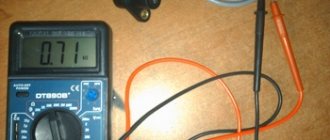
Checking resistance with an ohmmeter
Checking DPKV using an ohmmeter and an oscilloscope
This is the simplest method, but it does not provide a 100% guarantee that such a test will reveal a malfunction. For this procedure you will need a multimeter , which you must switch to resistance measurement mode (ohmmeter). With its help you need to measure the resistance of the inductor. This can be done by simply touching the multimeter probes in pairs to the coil terminals. Polarity does not matter in this case.
As a rule, the resistance value of most coils is between 500 and 700 Ohms. However, it is better to read the exact value in the documentation for the sensor or find it on the Internet. Accordingly, you need to set the upper limit on the multimeter - 2 kOhm (the limit may vary for different models of multimeters, the main thing is that it is larger than what is measured and closest to it). If, as a result of the measurement, you get a value close to the one indicated above, then everything is in order with the coil. However, it is too early to reassure yourself, because such a check is not complete. It is better to continue checking using other methods.
Checking the inductance value
Any coil in an excited state has its own inductance. The same applies to the one that is built into the DPKV body. The verification method is to measure this value. To do this you will need:
- megohmmeter;
- network transformer;
- inductance meter;
- voltmeter (preferably digital).
Some multimeters have a built-in inductance measurement function. If your device does not have it, then you should use additional equipment. In any case, the measured value of the inductance of the DPKV coil should be within 200.400 mH (in some cases it may differ slightly). If you receive a value that is very different from the specified value, then there is a high probability that the sensor is faulty.
Next you need to measure the insulation resistance between the coil wires. To do this, use a megohmmeter, setting the output voltage on it to 500 V. It is better to carry out the measurement procedure 2-3 times to obtain more accurate data. The measured insulation resistance value should not be lower than 0.5 MOhm . Otherwise, a violation of the insulation in the coil can be stated (including the possibility of an interturn short circuit). This indicates a malfunction of the device. The coil must be demagnetized using a mains transformer. However, the most advanced method for diagnosing CPPV is to use an oscilloscope.
What is DPKV?
The crankshaft position sensor (CPS) is also called the synchronization sensor. If it fails, the engine stops. Why is this happening? The reason is that, using a sensor, the electronic control unit synchronizes the operation of the gas distribution mechanism. Thanks to it, the moment is determined when a spark is supplied to the spark plugs and fuel is injected into each cylinder. If the sensor fails, problems with fuel injection occur and the engine stalls.
Device
The crankshaft sensor design consists of:
- sensitive element - magnetized steel core;
- cylindrical aluminum or plastic housing;
- bases with flange and mounting hole;
- connector for connecting to car wiring;
- communication cable with enamel insulation.
To ensure the reliability of the structure, the winding is sealed with a compound. The crankshaft synchronizing disk has 58 teeth located around the circumference at the same distance from each other, every 6 degrees. The pulley is missing two teeth that serve to determine the initial position of the crankshaft, thanks to which synchronization pulses are generated.
Synchronization sensor device
Working principle and functions
When the crankshaft turns, the teeth act on the device, changing its magnetic field, thereby generating voltage pulses. Thus, from the crankshaft sensor, a synchronizing pulse is sent to the controller, thereby informing it about the frequency and position of the crankshaft. This is the basis for calculating the moment of time required for the activation of the ignition module and fuel injectors. Communication with the ECU is carried out through a connector.
Obviously, if the synchronization device sends incorrect signals, the cyclicity of the ignition and fuel supply will be disrupted. This will lead to improper operation of the motor or to its stop (video author - StarsAutoCom).
Modern cars are equipped with different types of DPKV.
There are the following types:
- inductive type (magnetic);
- Hall sensor based on the Hall effect;
- optical sensor.
Since there are several types of synchronization devices, to replace it you need to take the device that is specified in the car manual.
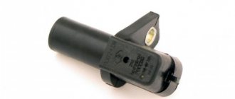
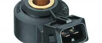
Appearance of DPKV
Possible malfunctions and their symptoms
It is important to understand that the DPKV cannot work poorly: it either works without interruption or fails. If there is a malfunction, CHECK lights up on the dashboard.
Signs of a faulty crankshaft sensor:
- car dynamics drop;
- spontaneous increase and decrease in engine speed;
- unstable operation at idle speed;
- under dynamic load, detonation occurs;
- The engine starts poorly or does not start at all.
The listed signs may be symptoms of problems with other devices or components. One of the symptoms is often idle speed. If the number of revolutions fluctuates, this does not always mean a problem with the synchronization sensor. To know for sure that the causes of problems are the failure of the DPKV, it is necessary to check the crankshaft sensor for functionality.
Purpose, device and principle of operation
The crankshaft position sensor is the main regulating function of the fuel injection system on a vehicle. Its presence ensures synchronous operation of each engine injector and the entire ignition system.
The driver consists of the following components:
- 1 — device of a nylon frame;
- 2 - magnetic circuits, these elements are made of steel;
- 3 - winding kit, for which thin copper wire is used;
- 4 - a layer of electrical circuit insulation, most often in the form of enamel or resin.
Unstable operation of the controller causes temporary interruptions in the fuel supply. During operation of the device, the vehicle control module, which is a microcontroller, ensures the correct piston position at a given time for each cylinder of the internal combustion engine.
To ensure adjustment using the device, the process is based on the following algorithm:
- The crankshaft of the power unit is equipped with a special gear. There are no two gears on it, this was done on purpose.
- When the machine's engine crankshaft begins to move, all the teeth move in close proximity to the controller. This contributes to strong distortions of its magnetic field.
- Signals are generated in the induction coil of the regulator when the shaft moves. Packet pulses are transmitted to the information base, which is located in the memory of the microcontroller. The two gears missing from the shaft are considered the starting point and also the zero point. Due to the absence of these gears, the microprocessor unit diagnoses the initial position of the crankshaft.
- The microprocessor in the car then counts the number of signals sent by the device. Then, after a certain time, the position of the crankshaft is determined.
- The processed pulse data is then sent by the control unit to the controller used to activate the fuel injector. The latter supplies fuel to the ignition system.
If the crankshaft position sensor is working properly, the vehicle's engine will operate at maximum power. The drive unit will require a minimum amount of fuel to achieve maximum power.
Types of sensors
It is worth discussing separately the different types of devices:
- Magnetic induction DPKV. Devices of this type do not require a separate battery for power. The voltage value at a certain time is initialized for the control module pulse. This occurs when the timing gear passes through a magnetic field. A magnetic field appears around the regulator, and the device itself controls the speed of rotation of the shaft and can be used as a speed regulator.
- Hall driver, its operation is based on the Hall effect. This indicates that the current transmission begins when the variable field is applied to the device. The synchronizer roller itself engages the field using gears that influence the field generated around the controller. Hall effect control unit used as ignition distributor.
- Optical type device. This type of driver includes a shaft that synchronizes with holes or teeth. The target causes an overlap of the light flux between the diode element and the receiver. The latter converts the received light flux into a signal. As a result, voltage is applied to the microprocessor module.
Diagnosis of the crankshaft sensor
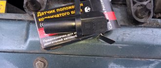
Before taking any troubleshooting measures, you need to find out the reason why the sensor is not working correctly. To do this, you need to disconnect it from the connector, remove it and check it. It is usually located on the oil pump cover.
Device location
After removing the device, you first need to do a visual inspection to identify mechanical faults. During inspection, you should pay attention to the integrity of the case, the condition of the contacts, core and terminal block. All dirt must be cleaned with alcohol or gasoline.
After a visual inspection, the crankshaft position sensor is checked using special instruments. The two most popular verification options are:
- The first way is with a multimeter. It is used to measure the winding resistance. The optimal winding resistance of the device should be in the range from 550 to 750 Ohms.
- For the second method, you will need several instruments: a voltmeter, a network transformer, an inductance meter, a megger. The inductance should be between 200 and 400 mH. The resistance of the sensor winding is measured by a tester. It must exceed 20 MΩ at a voltage of 500 V. The mains transformer is designed to remove magnetization from the synchronization disk.
Checking DPKV with a multimeter
Often, to identify a device malfunction, it is enough to measure the resistance of its winding.
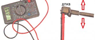
Checking with a wrench
DPKV is one of the main control parts, since without it the automobile power unit will not work. It is directly connected to the electric fuel pump, so the functionality of the sensor can be checked by focusing on this device.
This is much easier to do compared to other methods, since it does not require the use of special instruments to measure electrical parameters.
Experienced automotive electrician Valery Chkalov shared a simple testing technology on his Youtube channel.
He suggests using a simple wrench as a diagnostic tool:
- This method requires preliminary preparation. To better hear the operation of the fuel pump, you must first remove the rear seat inside the car and disconnect the sensor.
- Then you should take the key and turn on the ignition.
- You need to bring the key to the metal core of the DPKV, and then tear it off.
- If the sensor is in good condition, the fuel pump will turn on. This point is easy to hear. Otherwise, this part will need to be replaced.
Replacement features
Before making a replacement, be sure to check the DPVC for serviceability. The only way to fix the problem is to replace the crankshaft sensor. To change the DPKV, you need to prepare a key for “10”.
Replacing the crankshaft sensor consists of the following steps:
- First, turn off the ignition.
- Next you need to disconnect the connector. Through the connector, the device receives power and transmits information to the ECU.
ECU connection connector
When the connector is connected and the car's power is turned on, you can start the engine and check its dynamics, performance at idle, under dynamic load. Thus, signs of problems with the fuel system should disappear.