This article will talk about how to replace the gasket and tighten the cylinder head of a VAZ 2107. In fact, it’s not difficult to do it yourself, although you’ll have to tinker a little. The head gasket is a small and cheap element, but it affects the operation of the entire internal combustion engine. And first, it’s worth finding out what symptoms of a damaged gasket may appear.
Valve cover tightening torque for VAZ 2107
This article will talk about how to replace the gasket and tighten the cylinder head of a VAZ 2107. In fact, it’s not difficult to do it yourself, although you’ll have to tinker a little. The head gasket is a small and cheap element, but it affects the operation of the entire internal combustion engine. And first, it’s worth finding out what symptoms of a damaged gasket may appear.
Replacing the valve cover gasket of a VAZ 2108, 2109, 21099 engine
We will replace the valve cover gasket of the engine block head 21083 (2108, 21081) of VAZ 2108, 21081, 21083, 2109, 21091, 21093, 21099.
Such work will have to be done, for example, if there is an oil leak under the cover. It is also recommended to do this every time you remove the valve cover while repairing the car engine.
Necessary tools, accessories and spare parts
— New valve cover gasket for engine 21083 (21081, 2108)
— Key or head at “10”
Preparatory work
— Remove the car engine air filter housing
— Wipe the engine valve cover with a rag, removing dirt
Replacing the valve cover gasket of a VAZ 2108, 2109, 21099 engine
- Remove the engine valve cover
To do this, use a “10” key to unscrew the nut securing the carburetor throttle valve drive bracket and move it to the side.
Disconnect the two hoses of the crankcase ventilation system from the valve cover fittings. It is necessary to loosen the clamps with a Phillips screwdriver and tighten the hoses, turning them slightly to the right and left.
Fastening the valve cover of the VAZ 2108, 2109, 21099 engine
Using a wrench or socket 10, unscrew the two nuts securing the valve cover. Remove the nuts, large washers underneath them and rubber bushings.
Valve cover fastening parts for engines 2108, 21081, 21083 for VAZ 2108, 2109, 21099 cars
Remove the engine valve cover by lifting it up. If you can’t lift it on the first try (the sealant is stuck), pry it off with a screwdriver and repeat the removal.
Remove the valve cover of engine 21083 (21081, 2108)
- Remove the valve cover gasket
On engines 21083, 21081, 2108 this gasket is installed in a groove along the edge of the cover. Let's pull her out of there. If the first attempt fails (perhaps the gasket and the groove under it were lubricated with sealant), pry it off with a slotted screwdriver.
— Clean the groove for the gasket and the mating surfaces of the block head
For cleaning, you can use gasoline as a solvent, a wire brush and rags. Even if the entire gasket was not lubricated with sealant, it is still applied under its edges according to engine assembly instructions 21083, 21081, 2108. Therefore, we carefully remove its remains from the gasket and the mating surface of the cylinder head in order to later avoid loss of tightness.
Groove for the gasket in the valve cover of the VAZ 2108, 2109, 21099 engine
— Install a new gasket in the groove of the cover
The gasket can be placed in the groove in only one position since it is shaped. Apply a little oil-resistant sealant to the corners of the mating surface of the cylinder head under the valve cover. The layer thickness should be less than 1 mm. The gasket itself does not need to be lubricated.
Places for applying sealant on the mating surface of the engine block head, under the valve cover
— Install the valve cover on the car engine head
During installation, hold the gasket so that it does not fall out, become wrapped or pinched. There have been cases when, due to careless installation, the gasket became jammed on the back of the cover and oil was driven from there directly to the manifold.
We install rubber bushings and washers on the cover mounting studs. Tighten the nuts. The tightening torque is not large, just until it stops.
Notes and additions
— Along with replacing the valve cover gasket, it makes sense to clean the oil separator installed in it, since it can cause an increase in the pressure of crankcase gases in the engine, accompanied by squeezing out engine oil under the oil seals and seals (in particular, on the valve cover gasket).
Basic faults
There is damage to the gasket in which the operation of the VAZ 2107 is strictly prohibited. But there are also breakdowns in which it is still possible to drive. So, here is a list of the main breakdowns:
- Destruction of the gasket between the lubrication and cooling channels. With such a breakdown, antifreeze begins to seep into the engine sump. Of course, mixing with engine oil occurs. If there is a suspicion of a gasket failure, then you need to remove the dipstick and check the lubricant level. It's also worth looking at the consistency of the oil. In this case, the antifreeze turns light brown. In the event of such a breakdown, it is strictly forbidden to even start the engine, as this can quickly lead to jamming.
- Destruction between the cylinders and the cooling system occurs if the cylinder head gasket is of poor quality. It is quite possible that there was a weak tightening torque of the VAZ 2107 cylinder head during assembly. Under pressure, the integrity of the gasket is destroyed. The result is that air gets into the engine cooling system, and something terrible happens in the expansion tank. The temperature rises, there are huge bubbles and seething in the tank. Of course, it is undesirable to continue driving in this case.
- Sometimes (much less often than in the two previous cases) destruction occurs between adjacent engine cylinders. The result is a significant decrease in compression and unstable engine operation.
- And, of course, one cannot help but mention the banal marriage. In this case, the cylinder head gasket of the VAZ 2107 simply collapses, literally before our eyes. In this case, you can see how antifreeze begins to leak between the cylinder head and the engine block. In this case, tightening the bolts has no effect. Most likely, there is unevenness in the gasket itself, which leads to a similar result.
And now you have decided that you really need to replace the gasket, your car has one or more symptoms. What to do? Arm yourself with keys and other tools, and then begin preparation.
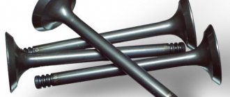
Purpose of valves in an engine
During operation, the engine consumes air and fuel and emits exhaust gases. The valves allow air-fuel mixture to enter the cylinder (through the intake valve) and exhaust gases to be removed (through the exhaust valve). The alternation of intake and exhaust cycles is called the engine duty cycle. It consists of four measures.
- Inlet. Inlet valve is open. The piston moves downwards and, due to the vacuum created in the cylinder, carries with it the air-fuel mixture, which enters through the open intake valve.
- Compression. Both valves are closed. The piston moves upward (toward the spark plug) and compresses the air-fuel mixture.
- Working progress. Both valves are closed. The spark plug produces a spark that ignites the air-fuel mixture. During combustion of the air-fuel mixture, a lot of gas is formed, which pushes the piston down.
- Release. The exhaust valve is open. The piston moves up and pushes exhaust gases out of the cylinder through the open exhaust valve.
The engine operating cycle consists of four strokes, during which the working mixture enters, is compressed and burns, then the exhaust gases are removed
More information about the design of the VAZ 2107 engine: https://bumper.guru/klassicheskie-modeli-vaz/dvigatel/remont-dvigatelya-vaz-2107.html
Video: how the engine works and the purpose of the valves
The meaning of valve adjustment
The opening of the valve is controlled by the camshaft cam. When the engine is running, the valve heats up and elongates, which can cause it to not close completely. To compensate for this elongation, there is a gap between the valve and the camshaft cam . The point of adjusting the valves is to set the required value of this gap.
Signs of improper valve adjustment
Signs of improperly adjusted valves include:
- Extraneous metallic knocking noise from under the valve cover.
- Reduced engine power.
- The smell of pure gasoline in the exhaust gases.
Adjusting the valves on VAZ 2107 cars is mandatory after repairing the gas distribution mechanism, as well as after a mileage of 10–15 thousand kilometers.
Find out more about the timing device: https://bumper.guru/klassicheskie-modeli-vaz/grm/grm-2107/metki-grm-vaz-2107-inzhektor.html
Video: operating principle of the gas distribution mechanism
Start of work
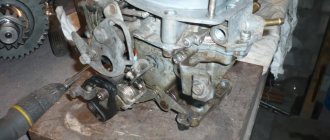
The very first step is to remove the air filter. Of course, on a carburetor engine it is somewhat easier to remove it. If you have an injector, you will have to tinker with its rubber fasteners. But the essence remains the same - it is necessary to disassemble the fuel system completely to get to the cylinder head. But we will look at the example of not an injection, but a carburetor seven. Still, there are many more classic cars with such a power system.
It is advisable to dismantle the carburetor, since if you remove the head along with it, you can accidentally damage it. On all classic series cars, the carburetor is removed in the same way. This procedure is quite simple, but it will take some time. Now you can unscrew the nut securing the distributor and remove the distributor along with the wires. Getting closer to the engine, all that’s left to do is drain the antifreeze from the system.
And then turn off all the pipes that you see. After this, it will be possible to dismantle the cylinder head cover. It is secured with nuts and shaped washers. Don't lose them during repairs. That's all, the preparation is complete, you can begin the most difficult part - dismantling and installing the cylinder head.
Valve stem seals
While adjusting the valves, it is quite possible that you had no idea that you were next to another very important element of the gas distribution mechanism - the valve stem seals.
Purpose of valve stem seals
While the engine is running, the camshaft, rocker arms, valve springs and valve tops operate in an oil mist. Oil is deposited on all parts and mechanisms located under the valve cover. Naturally, it also ends up on the top of the valves, called stems.
Under the influence of gravity, the oil will tend to flow into the combustion chamber. As you know, it shouldn't be there. Oil seals are designed to prevent oil from flowing down the valve stem into the engine combustion chamber.
Engine malfunctions associated with worn caps
The sole purpose of the oil seal is to prevent oil from draining into the engine combustion chamber . Over time, the rubber of this element loses its functions and is destroyed under the influence of an aggressive environment. This leads to the penetration of oil into the air-fuel mixture, where it burns successfully.
A working engine should have oil consumption of about 0.2 - 0.3 liters per 10 thousand kilometers. With worn valve stem seals, it can reach one liter per thousand kilometers.
Oil burning in the cylinders:
- clogs and destroys catalytic converters and particulate filters (devices that reduce the content of harmful substances in exhaust gases), which themselves are very expensive;
- causes overheating and premature failure of engine exhaust valves;
- greatly increases exhaust smoke;
- increases the risk of engine oil starvation due to lack of oil.
The service life of valve stem seals on domestic cars fluctuates around 80 thousand kilometers. This parameter very much depends on the quality of the caps themselves and the oil used.
What components are best to use?
Today, the greatest trust among car enthusiasts and mechanics is in the products of such well-known brands as Corteco and Elring - these brands have proven themselves to be the best in the production of gaskets, oil seals, seals, and valve stem seals.
There are products from domestic manufacturers on the market. Their quality varies greatly, but nevertheless does not reach the quality of the products of leading companies.
How to change valve stem seals
The topic of replacing valve stem seals is extensive and worthy of a separate article. Briefly it is done like this.
- Remove the valve cover.
- Remove the camshaft sprocket.
Video: replacing valve stem seals on a “classic”
Removing the cylinder head of a VAZ 2107
Now is the time to remove the timing chain. To do this, loosen the tensioner, or even better, remove it completely. Only after this can you unscrew the bolt that secures the sprocket to the camshaft. But don't forget to straighten the washer before you start unscrewing it.
To prevent the chain from falling, it must be held with a soft wire. Next comes the turn of the camshaft. It is secured to the cylinder head with nine nuts. The shaft is very easy to remove, there will be no problems with it. Then you need to get rid of the exhaust pipe and unscrew the exhaust manifold mounting nuts.
That's it, the withdrawal is almost complete. There are 11 bolts left that secure the head to the block. To unscrew them, you will need to use a socket wrench with a long handle. A dynamometer is not suitable for such purposes.
Gasket replacement and assembly
If your car had pronounced symptoms of a gasket failure, then you don’t even have to look for its damage; it still won’t be possible to repair it. Immediately buy a new one and put it in place. But you need to clean the entire surface that the gasket is attached to beforehand. There should be no remnants of the old one left. You can even evaluate how smooth the surface of the head and the block itself are. It is quite possible that the cylinder head has an uneven surface, which is why, no matter what gasket is installed, it very quickly begins to leak antifreeze or air.
Before installing the VAZ 2107 cylinder head, it is necessary to check the serviceability of all valves. If there is such a need, replace the seals. This will reduce oil consumption. When everything is complete, place the gasket on the block. Place the head on top. Please note that there are two types of gaskets - old and new. The latter is produced by a very thin layer of sealant around the entire perimeter.
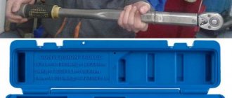
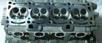
Do not forget to align the gasket so that it is positioned as accurately as possible. There are two guides for this purpose. And the time has come to tighten the cylinder head of the VAZ 2107. First, tighten all the bolts and tighten them by hand until they stop. And then you arm yourself with a torque wrench and, according to the diagram, tighten it. This diagram is shown in the figure. However, it is not difficult to remember it, since everything happens criss-cross.
It is necessary that all bolts are tightened as evenly as possible. To do this, they need to be pulled in two or three passes. During the first, the tightening torque of the VAZ 2107 cylinder head is 4 kgf*m. During the second pass, you need to set the moment to 11.5 kgf*m. The small bolt should be tightened to approximately 3.8. Installation of the camshaft is carried out in almost the same way; its fastenings will need to be tightened crosswise, but the moment here is not so important. The main thing is not to break the thread.
That's it, assemble your VAZ 2107 and try to start it. Just remember to fill the cooling system with water. If the engine is working perfectly and the gasket does not allow air or water to pass through, then you can add antifreeze.
We perform valve cover gaskets during engine repairs, cylinder head repairs, and when there are oil leaks from under the covers.
Remove the air filter housing from the carburetor.
Use a thin screwdriver to pry up and remove the spring clip.
Disconnect the rod from the throttle valve drive shaft.
Use a screwdriver to pry up and disconnect the throttle valve drive rod from the carburetor.
Use a screwdriver to pry up and remove the spring lock washer of the lever.
Remove the lever from the axle along with the rods.
Remove the carburetor fuel hose from the bracket.
Using a 10mm wrench, unscrew the eight nuts securing the cylinder head cover
Remove the special washers from the studs
Unclench the holder and release the vacuum brake booster hose and wiring harness
Adjusting valves VAZ 2107
- 1. Using a “10” socket wrench, unscrew the three nuts of the air filter and remove the cover
- 2. Having taken out the air filter, use a socket wrench “8” to unscrew the four nuts securing the air filter housing to the carburetor
- 3. Disconnect the air intake and the rubber hose of the crankcase ventilation breather from the breather cover
Breather hose, crankcase ventilation from breather cap
- 4. Remove the air filter housing along with the support plate
- 5. Next you need to disconnect the choke control cable
- 6. Then disconnect the carburetor drive rods
- 7. To remove the valve cover, it is necessary to unscrew all the nuts securing the valve cover using a socket wrench “10”
- 8. Then remove the cover
- 9. If you find that the chain tension is weak, loosen the chain tensioner nut located under the water pump.
- 10. Next, using a ratchet wrench “38”, turn the crankshaft 1-1.5 turns in the direction of rotation of the engine crankshaft, while the tensioner spring acting on the shoe will automatically adjust the chain tension
- 11. Tighten the tensioner nut and begin adjusting the VAZ 2107 valve
First, you need to know the order of operation of the cylinders in the engines of Moskvich, Zhiguli and VAZ-2121 Niva cars (1 - 3 - 4 - 2). Cylinder numbering starts from the end of the cylinder head or radiator towards the box. There are also numbers on the distributor cover (1,3,4,2) and, accordingly, each armored wire along its length stretches to its spark plug on the cylinders.
You must have the tool prepared in advance: open-end wrenches “13”, “17”, ratchet wrench “38”, a feeler gauge 15 hundredths of a millimeter thick.
Using a “38” ratchet wrench, turn the crankshaft clockwise until the mark on the camshaft pulley matches the mark on the camshaft housing. This position of the toothed pulley will correspond to the end of compression in the fourth cylinder (TDC).
In this position, the clearance at the exhaust valve of the third cylinder (6th cam) is adjusted. We repeat the same operation on the exhaust valve of the fourth cylinder (8th cam).
To adjust the gaps between the levers and cams, place a feeler gauge between the lever and the camshaft cam and loosen the locknut. Next, rotate the adjusting bolt to set the required clearance, followed by tightening the locknut.
In this case, the probe should move with slight pinching. The operation must be repeated if, as a result of tightening, the probe is pinched, or, conversely, moves freely.
Next, rotate the engine crankshaft 180 degrees or the camshaft 90 degrees clockwise. Then we adjust in the second cylinder (4th cam), and in the fourth cylinder (7th cam).
After each valve adjustment, pay attention to whether the cam has free play. Then we turn the crankshaft 180 degrees and adjust the valves in the first cylinder (1st cam) and in the second cylinder (3rd cam).
We rotate the crankshaft another 180 degrees and adjust the valves in the first cylinder (2nd cam) in the third cylinder (5th cam).
Important: adjust the valves only on a cold engine, the temperature not exceeding 40°C. On a cold engine, the gap between the camshaft cams and levers should be 0.15 mm, and the error in setting the gaps should not exceed 0.02-0.03 mm.
With all the gaps set, we install a new cork valve cover gasket, since the old gasket may be deformed when the cover was removed. We put on the valve cover and check that the cork gasket is seated correctly. If necessary, adjust the valve cover gasket very carefully.
Valve cover gasket for cylinder head VAZ 2101-1003270
Not forgetting to put on the washers, tighten all the nuts “10”. Tightening the valve cover nuts should begin from the center and gradually move to its edges. We put on the camshaft cover and connect the choke cable. We assemble the carburetor drive rods.
We install the air filter housing, connect the air intake, put on rubber hoses and radiator pipes. We secure the filter housing with nuts “8” (the main thing is not to break the thread). We install the filter element, put on the cover, and secure it with three “10” nuts.
Car enthusiast You know that the air filter must be replaced every 20 thousand kilometers...
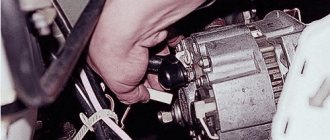
Now we check the tension of the generator belt; if it is loose, it needs to be tightened. To do this, loosen the nut securing the generator to the mounting plate and move the generator mounting away from the engine and tighten the mounting nut.
The normal deflection of the belt should be 12-17 mm from the thumb force of 3-4 kg per centimeter in the middle between the pump and generator pulleys. Check the belt tension every 10 thousand km.
I would recommend inspecting the engine cooling system before each trip. It is necessary to check the level of coolant in the expansion tank, check for leaks at the junction of the pipes with the thermostat, radiator, and pump. And if necessary, tightening the clamps will not take you much time.
If you decide to replace the coolant for any reason, it is drained through the drain hole in the cylinder block. To do this, you need to unscrew the radiator cap and the water temperature sensor at the bottom of the radiator. To unscrew the sensor, you must first disconnect the wires.
Chain tensioner shoes: (1) VAZ 2121; 21213-1006090-10; (2) VAZ 2103-1006090-10; (3) VAZ 2101-1006090-10 Chain stabilizer VAZ 2101; 2103-1006100-00
Table
The procedure for adjusting valve clearances on the “Classic” Lada 2101-2107 according to the table:
| Crank angle | Camshaft angle | Cylinder number | Valve number |
| 0° | 0° | 4 and 3 | 8 and 6 |
| 180° | 90° | 2 and 4 | 4 and 7 |
| 360° | 180° | 1 and 2 | 1 and 3 |
| 540° | 270° | 3 and 1 | 5 and 2 |
Valve counting from left to right starts from the camshaft sprocket side.
You can adjust the valves of the VAZ 2107, replace the coolant, do minor repairs yourself and service the VAZ car yourself. BUT, if you have extensive experience in operating a car or you have golden hands.
Good luck to you and see you soon on the pages of the RtiIvaz.ru blog!
Video
Tightening torques for cylinder head VAZ 2107
- 121 0 110k
When assembling the cylinder head after replacing the gasket or repairing the cylinder head, it is important to tighten the bolts to the torque recommended by the automaker. But different instructions suggest using two different schemes for tightening the VAZ-2107 cylinder head with a torque wrench. Let's figure out what is their difference, and how the cylinder head is tightened on a VAZ 2107 , and with what force.
The table below shows both options for the cylinder head tightening torque diagram on a “classic” VAZ, depending on the type of bolt. Because classic bolts require only two passes , but modern torsion bolts , due to their properties, require four passes . In the article we will look at everything in more detail.
| Bolt type | Diagram and tightening torques of the VAZ-2107 cylinder head bolts |
| Classic bolts | During the first pass, the bolts are tightened to 4.0 kgf/m. During the second pass , tighten the bolts with a torque of 11.5 kgf/m. Bolt No. 11 size M8x45 is tightened with a torque of 3.8 kgf/m. |
| Torsion bolts with elastic deformation | On the first pass , tighten the bolts with a torque of 2.0 kgf/m. During the second pass, it is necessary to tighten with a force of 8 kgf/m. During the third pass, tighten all the bolts at an angle of 90 degrees. For the fourth, you need to tighten all the bolts 90 degrees again. Bolt No. 11 size M8x45 is tightened with a torque of 3.8 kgf/m. |
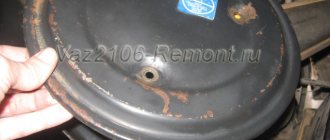
What types of valve covers are there?
There are several types of flap covers.
Depending on the type of lid, you need to select a liner. 1970-1974 The cover is more angular than later ones, the stamping under the timing star is high, the oil filler neck is high.
Full size
1974-1979 The oil filler neck is high, the timing star stamping is low, the corners are rounded
Full size
1980 onwards Same thing, but with a low neck
The injection version does not have a gas drive bracket; there is an air duct mounting bracket on the front part.
Cover 2123-1003260 (Shniva) has a double wall and a threaded neck.
Full size
As suggested by Dim23rus, the 2105 covers also come in different shapes, round and angular
Well, homemade/cooperative/dealer options
The last one is produced by BIMOtorsWhat is the function of the gasket?
As soon as the cuff loses its properties, the motor starts to leak. The gasket ensures complete tightness of the lid and neck for filling the lubricant.
The element is located under the valve mechanism cover and is attached with it using bolts and nuts. The cuff is made of a special type of rubber that does not lose its characteristics for a long time when heated. Then the quality of the material gradually deteriorates, the part loses its elasticity and is unable to hold oil under pressure. You have to shoot and think what to do next.
Why is correct tightening of the VAZ-2107 cylinder head important?
If you have replaced the cylinder head gasket, and besides major repairs, this is practically the only reason to disassemble the cylinder head, then the exact sequence and tightening torque of the VAZ-2107 cylinder head are critically important for the correct operation of the engine. Because any discrepancies in the fit of the valve cover lead to problems in the engine processes.
If the cylinder head of the VAZ-2107 is not tightened, then the parts of the engine will not be pressed against each other enough, even despite the presence of a gasket. The result is a drop in compression and burnout of the gasket. Also, working gases from the cylinders can enter the channels of the lubrication or cooling system and lead to the entry of these technical fluids into the combustion chamber. And this is already very bad - antifreeze in the oil will lead to insufficient lubrication of engine parts with all the ensuing consequences.
Antifreeze in VAZ 2107 engine oil
Traces of burnout of the cylinder head gasket on the cylinder block of a VAZ 2107
You also cannot tighten the cylinder head cover - this can damage it. Either cracks will appear in it immediately, or tension will arise, which will lead to this in the future. Also common is bolt rupture and thread stripping.
If you tighten the bolts in one place and not tighten them in another, the cylinder head of a VAZ-2107 car or its cover may warp. This will result in gaps that the gasket cannot compensate for. The result is the same as with loose bolts.
If not changed in a timely manner
On some cars, gasket failure is a chronic problem. The original standard part can withstand no more than 70-80 thousand kilometers. During active use of the car, it breaks down even before the mileage of 40 thousand km.
Changing the gasket on time is extremely important. If this is not done, there will be many unpleasant surprises: the entire valve group of the engine will be subject to a powerful attack of dirt and dust, which will penetrate inside without obstacles; severe oil leakage will begin, and a lack of lubrication will have an extremely negative effect on the service life of the piston group and valves; oil will get on sensors, spark plug wells, wires, and other mechanisms in the engine compartment - the risk of fire will increase; cooling of the power plant will become worse.
Change the gasket as soon as it stops doing its job. If you choose a low-quality product or make a mistake during replacement, oil leaks will appear again within a few days after replacement.
This is interesting: Replacing the low beam lamp on a Nissan JUKE, photo and video instructions
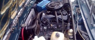
Tightening torques for the VAZ-2107 block head on carburetor and injection engines
For the most part, the “seven” was equipped with carburetor engines of various modifications. Moreover, the most common version was a 1.5 liter engine with 77 hp. Although modifications of 1.3, 1.4 and 1.6 liters were also produced. There is no fundamental difference in the tightening torque of the cylinder head of the VAZ 2107 injector and carburetor.
The procedure for tightening the cylinder head bolts on a VAZ 2107 engine
The cylinder head of an injection engine differs structurally only in the enlarged “windows” of the intake manifold channels, because the injector needs a little more air than the carburetor. But the tightening force of the VAZ-2107 cylinder head for such engines will be the same.
The instruction manual for the VAZ Seven contains clear data. Firstly , the tightening order is important (see picture). Secondly , first you tighten the bolts by hand, and then tighten bolts No. 1-10 in two stages with the force indicated in the table (in newton and kilogram per meter). Bolt No. 11 is reached last, in one approach, with a force of 3.8 kgf/m.
| Tightening stage | Rated torque, Nm (kgf/m) | Minimum, N m (kgf/m) | Maximum, N m (kgf/m) |
| Preliminary | 39,2 (4,0) | 33,3 (3,4) | 41,16 (4,2) |
| Final | 112,7 (11,5) | 95,94 (9,79) | 118,38 (12,08) |
Tightening the cylinder head of the VAZ 2107 - second option
On some newer “sevens”, not ordinary M12x120x1.25 bolts were used to fasten the cylinder head, but torsion bar bolts - M12x115x1.25. Therefore, in addition to the first option of the sequence and degree of tightening, there is another option with data on the tightening force of the VAZ-2107 cylinder head. The process itself looks like this:
- Stage 1. Tightening the bolts to a torque of 2.0 kgf/m.
- Stage 2. Second tightening with a torque of 7.5-8.5 kgf/m.
- Stage 3. Turn each bolt 90 degrees.
- Stage 4. One more turn of all bolts by 90°.
- Stage 5. Tighten bolt No. 11 with a force of 3.8 kgf/m.
Different bolts and tightening degree of the VAZ-2107 cylinder head. What is the difference
The “classic” was originally equipped from the factory with ordinary M12x120x1.25 bolts for a 19mm head. Their original catalog number was 2101-1003271 or 21213-1003271. The second number suggests that such bolts were also used on the VAZ-21213 Niva, which is why they are also called “Niva bolts”. Another colloquial name is “penny”. But most often they are simply identified as “cylinder head bolts for an old-style classic.”
On VAZ-2108 and VAZ-2109 cars, torsion bolts of a new type began to be used, which are also suitable for the “classics” - M12x115x1.25. They were unscrewed and tightened with a 12mm hexagon. It is noteworthy that AvtoVAZ’s catalog number remained the same, 21213-1003271. And it is the bolts of the new type that are sold in the original packaging. Their difference is that they “stretch” - and if correctly, they undergo elastic deformation. Actually, this is why you need to turn it twice by 90 degrees.
Old style cylinder head bolt
New sample cylinder head torsion bolt
Pay attention to the length of these bolts, encoded in the markings. 5mm difference with regular bolts. It is by these 5 millimeters that the bolt is deformed, completely filling the internal thread.
What is the difference between these bolts, other than the first ones are not sold in the original packaging and different bolts require different torque patterns? Classic bolts can be used many times if their condition allows it. But on the other hand, you need to remember to do preventive tightening of the cylinder head bolts . About once a year , or more often, you will have to check the tightening torque of all the head bolts of your VAZ-2107 and tighten them if necessary.
The new type bolts do not require such a procedure, because due to elastic deformation they provide constant pressure on the cylinder head cover . But such bolts are disposable . When disassembling the cylinder head, you will have to buy a set of new ones. And unscrewing such bolts can be complicated by the fact that bolts tightened without a torque wrench can break .
Fresh questions for auto repair shops (replacing the valve cover gasket for vaz lada 2107) in Moscow
I want to write a review about this service. I am repairing my Zafira there, the most important thing is that there is no deception there, they don’t impose anything, they don’t scam me. Vice versa! Warn against unnecessary spending! About the quality, I can say something about what they did.
Good afternoon do you have a vibration stand?
Hello! I need to replace the rear brake pads on a Peugeot Partner Teepee. Is it possible to do this at your place and what is the price for such work? Thank you.
Hello, please tell me how much it costs to repair the front axle gearbox of a 2005 Tuareg? And when can you come?
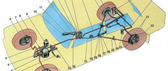
Tightening torques for main threaded connections of VAZ PP
Tightening torques for various main threaded connections of vehicle components. These tightening torques can only be ensured using special equipment (torque wrench) Part Thread Tightening torque, N•m (kgf•m)
Engine Cylinder head mounting bolt M12x1.25 cm. Note 2 Stud nut securing the intake pipe and exhaust manifold M8 20.87–25.77 (2.13–2.63) Tension roller mounting nut M10×1.25 33.23– 41.16 (3.4–4.2) Nut of the camshaft bearing housing stud M8 18.38–22.64 (1.87–2.31) Bolt of the camshaft pulley M10 67.42–83.3 ( 6.88–8.5) Bolt for fastening the housing of auxiliary units M6 6.66–8.23 (0.68–0.84) Nut for the stud fastening the outlet pipe of the cooling jacket M8 15.97–22.64 (1.63– 2.31) Bolt for fastening the main bearing caps M10x1.25 68.31–84.38 (6.97–8.61) Bolt for fastening the oil sump M6 5.15–8.23 (0.52–0.84) Nut connecting rod cover bolt M9x1 43.32–53.51 (4.42–5.46) Flywheel mounting bolt M10x1.25 60.96–87.42 (6.22–8.92) Coolant pump mounting bolt M6 7, 64–8.01 (0.78–0.82) Crankshaft pulley mounting bolt M12x1.25 97.9–108.78 (9.9–11.1) Coolant pump supply pipe mounting bolt M6 4.17– 5.15 (0.425–0.525) Nut for fastening the exhaust pipe of the muffler M8×1.25 20.87–25.77 (2.13–2.63) Nut for fastening the flange of the additional muffler M8×1.25 15.97–22, 64 (1.63–2.31) Nut securing the clutch cable to the engine bracket M12x1 14.7–19.6 (1.5–2.0) Bolt securing the front engine mount bracket M10x1.25 32.2–51, 9 (3.3–5.5) Nut of the bolt securing the front engine mount M10 41.65–51.45 (4.25–5.25) Nut of the bolt securing the left mount of the power unit suspension M10 41.65–51.45 (4.25–5.25) Nut securing the left suspension support of the power unit M10 31.85–51.45 (3.25–5.25) Bolt securing the rear suspension support of the power unit M10x1.25 27.44–34 ( 2.8–3.47) Nut of the bolt securing the rear suspension support of the power unit M12 60.7–98 (6.2–10) Bolt securing the oil receiver to the main bearing cover M6 8.33–10.29 (0.85– 1.05) Bolt for fastening the oil receiver to the pump M6 6.86–8.23 (0.7–0.84) Bolt for fastening the oil pump M6 8.33–10.29 (0.85–1.05) Bolt for fastening the housing oil pump M6 7.2–9.2 (0.735–0.94) Oil pump pressure reducing valve plug M16x1.5 45.5–73.5 (4.64–7.5) Oil filter fitting M20x1.5 37 .48–87.47 (3.8–8.9) Oil pressure warning lamp sensor M14x1.5 24–27 (2.45–2.75) Carburetor mounting nut M8 12.8–15.9 (1.3 –1.6) Nut securing the cylinder head cover M6 1.96–4.6 (0.2–0.47) Clutch Nut securing the clutch housing to the engine block M12x1.25 54.2–87.6 (5.53– 8.93) Bolt securing the clutch housing to the engine block M12x1.25 54.2–87.6 (5.53–8.93) Bolt securing the guide sleeve flange of the clutch release bearing M6 3.8–6.2 (0. 39–0.63) Bolt securing the clutch housing to the flywheel M8 19.13–30.9 (1.95–3.15) Nut securing the clutch housing to the gearbox M8 15.7–25.5 (1.6–2 ,6) Bolt securing the bottom cover to the clutch housing M6 3.8–6.2 (0.4–0.6)
Gearbox Conical screw fastening the drive rod joint M8 16.3–20.1 (1.66–2.05) Bolt fastening the gear selection mechanism M6 6.4–10.3 (0.65–1.05) Bolt fastening the housing gear shift lever M8 15.7–25.5 (1.6–2.6) Nut securing the drive rod and torque rod clamp M8 15.7–25.5 (1.6–2.6) Nut of the rear end of the primary and secondary shaft M20x1.5 120.8–149.2 (12.3–15.2) Reverse light switch M14x1.5 28.4–45.3 (2.9–4.6) Bolt securing the forks to the rod M6 11.7–18.6 (1.2–1.9) Differential driven gear mounting bolt M10x1.25 63.5–82.5 (6.5–8.4) Speedometer drive housing mounting nut M6 4.5– 7.2 (0.45–0.73) Bolt securing the gear selector lever axle M6 11.7–18.6 (1.2–1.9) Nut securing the rear cover to the gearbox housing M8 15.7–25, 5 (1.6–2.6) Reverse fork clamp plug М16×1.5 28.4–45.3 (2.89–4.6) Conical screw fastening the gear selector rod lever М8 28.4–35 ( 2.89–3.57) Clutch housing and gearbox mounting bolt M8 15.7–25.5 (1.6–2.6) Drain plug M22x1.5 28.7–46.3 (2.9– 4.7)
Front suspension Nut securing the upper support to the body M8 19.6–24.2 (2–2.47) Nut securing the ball pin to the lever M12x1.25 66.6–82.3 (6.8–8.4) Eccentric nut bolt for fastening the telescopic strut to the steering knuckle M12x1.25 77.5–96.1 (7.9–9.8) Bolt for fastening the telescopic strut to the steering knuckle M12x1.25 77.5–96.1 (7.9–9. 8) Bolt and nut for fastening the suspension arm to the body M12x1.25 77.5–96.1 (7.9–9.8) Nut for fastening the brace M16x1.25 160–176.4 (16.3–18) Bolt and nut mounting the stabilizer bar to the arm M10x1.25 42.1–52.0 (4.29–5.3) Nut securing the stabilizer bar to the body M8 12.9–16.0 (1.32–1.63) Bolt fastening the brace bracket to the body M10x1.25 42.14–51.94 (4.3–5.3) Nut securing the telescopic strut rod to the upper support M14x1.5 65.86–81.2 (6.72–8.29 ) Bolt securing the ball joint to the steering knuckle M10x1.25 49–61.74 (5.0–6.3) Nut of the rear wheel hub bearings M20x1.5 186.3–225.6 (19–23) Nut of the front wheel hub bearings M20x1.5 225.6–247.2 (23–25.2) Wheel bolt M12x1.25 65.2–92.6 (6.65–9.45) Rear suspension Nut securing the lower end of the shock absorber M12x1, 25 66.6–82.3 (6.8–8.4) Nut for fastening the rear suspension arm M12x1.25 66.6–82.3 (6.8–8.4) Nut for fastening the brackets for the suspension arms M10x1.25 27 .4–34 (2.8–3.46) Nut securing the upper end of the shock absorber M10x1.25 50–61.7 (5.1–6.3) Brakes Bolt securing the brake cylinder to the caliper M12x1.25 115–150 (11 ,72–15.3) Bolt for fastening the guide pin to the cylinder M8 31–38 (3.16–3.88) Bolt for fastening the brake to the steering knuckle M10x1.25 29.1–36 (2.97–3.67) Bolt mounting the rear brake to the axle M10x1.25 34.3–42.63 (3.5–4.35) Nut securing the vacuum booster bracket to the bracket booster M8 9.8–15.7 (1.0–1.6) Nut mounting the main cylinder to the vacuum booster M10 26.5–32.3 (2.7–3.3) Nut securing the vacuum booster to the bracket booster M10 26.5–32.3 (2.7–3.3) Nut of brake connections pipelines M10 14.7–18.16 (1.5–1.9) Front brake flexible hose end M10x1.25 29.4–33.4 (3.0–3.4)