Using inexpensive and widespread integrated circuits TDA1557, TDA1558, you can assemble a simple low-frequency power amplifier that requires a minimum number of external components.
The amplifier on this chip was previously widely used in car radios. From an old car radio that has long since outlived its usefulness, you can unsolder or even cut out a full-fledged power amplifier with a section of the board.
It can be adapted to amplify the sound of a computer, laptop, DVD and various types of set-top boxes.
TDA1557Q, TDA1558Q - monolithic class B integrated amplifier in a plastic case.
| Parameter | min. meaning | Max. meaning |
| Supply voltage, V | 6 | 18 |
| Current consumption in pause mode, mA | 100mA | |
| Maximum crystal temperature, C | ||
| Gain, dB | 45 | 47 |
| Bias voltage, mV | 250 | |
| Channel separation, dB | -40 | |
| Gain difference between channels | 1dB | |
| Distortion factor at output power up to 12W | 0,5% | |
| Output power, THD 10%, 4 Ohm, W | 22 | |
| Peak current consumption, A | up to 4 | |
| Critical crystal temperature, Celsius | 150 | |
| Channel separation no less than, dB | 40 | |
| Gain difference between channels no more than, dB | 1 | |
| Frequency response unevenness in the frequency range 25-20000 Hz no more, dB | 1 | |
| Duration of soldering one terminal with solder 300-350 C no more than, sec | 3 |
We make the car amplifier 8212 ourselves
Sun 24 Nov 356 Category: Power amplifiers
A simple, fairly powerful and cheap car amplifier can be implemented at minimal cost in just one day. This project is designed to prove #8212 how small and cheap a full-fledged amplifier for a car can be. 12-Volt microcircuits powered from the on-board network of a car battery cannot provide the necessary power to power the subwoofer heads, therefore, there is a need to use more powerful amplifiers with bipolar power.
The main problem with using powerful amplifiers is that to power them you will need to use a voltage converter, which will provide the necessary parameters to power the amplifier.
Inverter #8212 is a serious thing and if someone is assembling it for the first time and has no experience, then it is better not to contact him.
In my case, it was necessary to assemble a simple amplifier with an output power of 100-120 watts to power the subwoofer.
The choice immediately fell on the TDA7294 microcircuit, although I initially planned to implement it with transistors, but if we are talking about a low-power subwoofer amplifier, then transistors are inferior to microcircuits.
The amplifier microcircuit is connected according to a standard circuit; I will not dwell on assembling the amplifier, since there is nothing complicated about it.
The main characteristics of the TDA7294 chip are as follows.
Main characteristics
The sound volume directly depends on the output power of the device. The higher this indicator, the louder and undistorted sound the speakers can reproduce.
The output power for a subwoofer should be higher than for full-range speakers. Another important characteristic is the output impedance. The smaller it is, the higher the output power and current consumption of the device.
Subwoofer amplifier circuit
DIY subwoofer box
The schematic diagram of a subwoofer amplifier looks like this:
The signal coming from the radio must be processed in a certain way so that it does not lose its quality after amplification. For this purpose, a device such as an adder is used.
The signal passing through the board being created is “cut off” in such a way that the DIY subwoofer amplifier ultimately produces sounds in the range from 16 to 300 Hertz. We will also need a power circuit switching unit that will prevent the amplifier from over-discharging the car battery.
Attention: the coil voltage in the installed relay must be 12V, and the contact current must be no less than 20A. To power installed relays, a separately output terminal (REM) is used.
It can be connected to one of the radio outputs, which supports +12V power supply. Thus, in principle, we cannot accidentally leave the amplifier on - it will turn off when the radio is turned off, and, accordingly, will also turn on with it. You can supplement your car subwoofer amplifier with your own hands using LEDs that show when it is on and off.
Please note that the transformer for the circuit is wound on a ferrite ring, 40x25x11. It is pre-processed with a file and wrapped with electrical tape.
First, the primary winding of the ring is carried out - this is done using five strands of wire with a diameter of 0.9 mm or less. Then the wires are twisted so that the tips remain for the inputs in the board. Insulation is also wrapped over the wire wound around the ring.
We begin to re-wind from the top, using a thicker wire for this purpose, with a diameter of 1.5 mm. In the same way, we end up leaving 4 twisted bundles of wires for the corresponding inputs on our board.
After the individual parts for a simple subwoofer amplifier have been made with your own hands, all that remains is to assemble it in one housing. In principle, it is possible to manufacture it on one board, but such a solution is more expensive and requires additional calculations.
A similar circuit can be used not only for car subwoofers, but also when creating the most common amplifier for home audio equipment. How to make an amplifier for a subwoofer with your own hands is shown in the diagrams above; all that remains is to provide a drawing of the “box” itself for a homemade home subwoofer.
Before I start my article, I want to say that if you have strong nerves, a lot of free time, certain skills in electronics, like to listen to very loud music in the car, powerful bass and are willing to spend a lot of money on such a project, then this article is just for you !
The idea of creating a high-power amplifier has been around for a long time, but due to lack of time and finances, the project was postponed. And then summer... vacation... It was decided to turn the idea into reality and exactly 3 months were spent for this, since there were big problems with the parts, but despite this, the amplifier complex was successfully assembled and tested.
To begin with, I would like to clarify the meaning of the expression “enhancing complex”. The fact is that it was decided to assemble a high-quality amplifier that could power the entire car audio system. The entire power section (power amplifiers) had to be combined “under one roof”, the result was 5 separate amplifiers with a total power of 680 watts, do not confuse with Chinese watts, there is a pure 680 watts of rated power, the maximum power of the system reaches 750 watts. The requirements for the complex were as follows. 1) High sound quality 2) High output power 3) Relatively simple design 4) Low cost compared to the prices of factory systems of this kind 5) Ability to power 10 -12 speakers + subwoofer To implement this idea, 5 separate power amplifiers were used, including a high-quality amplifier based on the Lanzar circuit to power the subwoofer channel.
Below are the parameters and series of microcircuits that were used in this amplifier. TDA 7384 - 4x40W (2 pieces, total chip power 320 watts or 8 channels, 40 watts per channel) TDA 2005 - 1x20W (2x10W) (2 pieces, total power 40 watts or 2 channels 20 watts each)
The above microcircuits are designed to power front speakers. This solution is the most economical; to create an amplifier of this kind, you can find out about the monetary costs at the end of the article. The most difficult part in any amplifier of this kind is the voltage converter, it is designed to power the subwoofer amplifier, perhaps we’ll start with it. Voltage transformer
It took me exactly two weeks to create.
The voltage converter pulse generator (from now on PN) is built on a traditional TL494 microcircuit. This is a high-precision push-pull PWM controller, a domestic analogue of 1114EU3/4. The microcircuit does not contain an additional output amplifier. The additional stage is built on low-power transistors, the signal from them is fed to the gates of the field switches.
The circuit is known as a push-pull or push-pull converter. The circuit is not new, but I had to change some of the circuit values to suit my needs. On each shoulder there are two powerful field workers of the IRF3205 series. Through heat-conducting gaskets they are mounted on heat sinks that were removed from computer power supplies
In the rectifier part, KD213A diodes are used, they are just for such purposes, since they can operate at frequencies of 70-100 kHz, and the maximum current reaches 10 amperes; in this circuit, the diodes do not need additional heat sinks, I did not notice any overheating.
I used 2 relays for power supply, 20 amperes each, but it is advisable to install a relay for 50-60 amperes, since the converter draws a considerable current. The remote control system (REM) is implemented in the PN, i.e. No powerful switches are needed to turn on the subwoofer. By applying plus to the remote control, the relays are instantly activated and power is supplied to the converter.
I especially struggled with winding the transformer, since the transformer was of my own design. Unfortunately, I could not find ferrite rings, so I had to go for an alternative solution. We got several computer power supplies for free, and large transformers were soldered out of them.
The ferrite halves are tightly glued to each other, so they need to be heated with a lighter for 30 seconds, then carefully removed from the frame. As a result, the standard windings were unwound from the transformers, and the terminals were cleaned.
Next, the side wall of each frame was cut off.
At the end the frames are attached to each other. The result is one elongated frame onto which we can freely wind the windings we need
Through experiments, the required number of turns in the primary winding was found. As a result, the primary winding contains 10 turns (2x5vit) with a tap from the middle.
Winding was done immediately with 5 strands of 0.8 mm wire. First, 5 turns are wound along the entire length of the frame, then we insulate the winding and wind another 5 turns on top identical to the first. We wind the windings IN THE SAME DIRECTION, for example clockwise.
After winding the wires, we twist them into a pigtail, not forgetting to remove the varnish in advance, then we tin them and cover them with a layer of tin. Now you need to phase the windings. In fact, there is nothing difficult here, you just need to find the “beginning” and “end” of the windings and connect, for example, the beginning of the first winding with the end of the second or the beginning of the second with the end of the first, the connection point is a tap to which the plus from the general power supply is supplied ( see diagram). After phasing the windings, we wind a test secondary winding; it is needed so that if the phasing is incorrect, we do not wind the entire secondary winding. The test winding can contain any number of turns, for example 3 turns with 0.8 mm wire, then we assemble the transformer by inserting the core halves.
When turning on the circuit, the transformer should not emit a “buzz”; the transistors should not overheat if the converter is idle. We connect a 12-volt incandescent lamp of a couple of watts to the secondary winding, which should light up with almost full heat, while the transistors should be cold and only after a few minutes of operation you can feel a slight heat release. If everything is normal, then remove the test winding and wind in its place a normal one, which is wound according to the same principle as the primary.
This time the winding is wound with two strands of 0.8-1mm wire and contains 30 turns (2x15 vit). Two identical windings are wound, each with 15 turns and stretched along the length of the entire frame. After winding the first half, we insulate the winding and wind the second one on top. The windings are phased according to the same principle as the primary.
After winding the secondary winding, the wires at the ends are twisted and tinned. At the final stage, the core halves are strengthened. The transformer is ready!
IMPORTANT! In converters of this kind (push-pull) there should be no gap between the halves of the core! Even the slightest gap of a fraction of a millimeter will lead to a sharp increase in the quiescent current and overheating of the field-effect transistors! It was because of my clumsiness that I burned several field-effect transistors. Make sure that the ferrite halves are pressed against each other as tightly as possible. Such a transformer is capable of providing the required voltage and current to power the subwoofer amplifier. We solder the transformer onto the board and begin winding the chokes.
Chokes The circuit uses 3 chokes. They are designed to filter out RF noise and interference that can form on the power lines. The main choke is used on the positive power line of the converter. It is wound with 4 strands of 0.8 mm wire. The ring used those in computer power supplies. The number of throttle turns is 13.
The remaining two chokes are located after the diode rectifier in the PN, they are also wound on rings from computer power supplies and contain 8 turns of 3 cores of 0.8 mm wire.
To be honest, I didn’t expect that such a high-quality voltage supply would be obtained, the quiescent current of the circuit does not exceed 200 mA, this is normal for such a monster, the output voltage is +/-63 volts, the slope is insignificant, only half a volt. The maximum power of the converter would allow powering two of these amplifier, but here it works with a large margin.
Amplifiers based on TDA2005, for low-power heads
Assembling this block took only 2 hours. During this time, two identical power amplifiers were assembled. The amplifiers were chosen as the cheapest option for low-power speakers; they can be used to power speakers located on the front panel of the car. Each microcircuit develops 20-24 watts of power and has very good sound quality.
Each microcircuit is connected via a bridge circuit; with a stereo connection, one microcircuit is capable of delivering up to 12 watts into a 4 ohm load
The microcircuits are installed on the heat sink through an insulating gasket. The volume is adjusted in advance using a regulator. At first, another board was planned, amplifiers were assembled from this one, then a general board was invented, which was entered into the project archive.
TDA 7384 for front speakers
For more powerful speakers, TDA 7384 quadraphonic microcircuits are used. Each microcircuit is capable of delivering up to 40 watts of power per channel into a 4 Ohm load. The result is 8 channels of 40 watts, sounds very good.
Such microcircuits are used in car radios; if you are too lazy to buy them, you can get them from non-working radios.
Microcircuits have different filters independent of each other; if you use a common filter, then noise and excitation are possible. Both amplifiers start working when +12 volts are supplied from the battery to the REM pin. The amplifiers were assembled on one board, but later the blocks had to be rearranged, so each amplifier was implemented on a separate board.
Subwoofer amplifier
The famous Lanzar circuit, full description, assembly, circuit and configuration are described here, so there is no need to talk about this amplifier. The amplifier is completely assembled using transistors, has very good sound quality and increased output power. I made some changes in the diagram and below is the diagram I used to assemble it, the original diagram in the same forum thread.
Since I could not find some of the circuit ratings, I had to make some changes, in particular the emitter resistors were replaced with 0.39 Ohm 5 watts. The BD139 transistor was replaced with a domestic analog KT815G, in addition, the low-power transistors of the differential stages and pre-output stages of the circuit were replaced.
Electrolytic capacitors can be removed at the input if the input is replaced with 2.2 µF or more.
It is advisable to do the first start-up of the amplifier with one pair of output transistors with the input shorted to ground, so that in case of breakdowns the transistors of the final stage do not burn out; they are the most expensive thing in this amplifier.
Pay special attention to the installation of the circuit, monitor the pinouts of the transistors and the correct connection of the zener diodes, the latter, if connected incorrectly, work like a diode. I installed a regular quiescent current regulator, I do not advise anyone to repeat my mistake, it is better to install a multi-turn one, it can be used to accurately adjust the quiescent current of the circuit, also convenient for setup.
The output stage of the amplifier operates in AB mode, this is essentially a fully symmetrical circuit, the level of nonlinear distortion is reduced to a minimum. Due to its high performance, this amplifier belongs to the Hi-Fi category; getting 300 watts from this amplifier is not a problem. It is also possible to connect a 2 Ohm load at the output, i.e. you can power as many as two subwoofer heads by connecting them in parallel. In this case, you cannot raise the amplifier voltage above 45-50 volts.
You can increase the power of the amplifier by adding one or two more pairs of output transistors, but do not forget about increasing the power supply, since the output power of the amplifier directly depends on the power supply.
AC protection
Despite the fact that the power amplifier is quite reliable, sometimes problems can occur. The output stage is the most vulnerable part of any amplifier; due to the failure of the output transistors, a constant voltage is formed at the output. The constant disables the expensive dynamic head. Any amplifier of this kind has protection that will protect the speakers from constant voltage. When the amplifier is turned on, the relay closes, including the head; with a constant voltage at the output of the PA, the relay opens, maintaining the head
The protection has a relatively simple circuit, contains 3 active components (transistors), a 10-20 ampere relay, and the rest is little things. When the PA is turned on, the relay closes with a slight delay. Power for protection is supplied from one arm of the converter, through a limiting resistor of 1 kiloohm, select a resistor with a power of 1-2 watts.
Low-power transistors can be replaced with any others whose parameters are similar to those used. The relay is connected to the collector of a more powerful transistor, therefore, the final transistor needs a more powerful one. From the domestic interior, you can use transistors KT 815.817 or more powerful - KT805.819. I noticed heat generation on this transistor, so I mounted it on a small heat sink. Protection and output signal indicator are mounted on one board.
Stabilization block
Bipolar voltage stabilizer provides the necessary voltage to power the filter unit and audio signal indicator. Zener diodes stabilize voltage up to 15 volts.
This unit is assembled on a separate board; it is advisable to use zener diodes with a power of 0.5 watts
Audio level indicator
I won’t go too deep into the operation of the circuit, since the circuit of such an indicator is described in one of my
article.
The indicator uses LM324 microcircuits. It is advisable to use an operational amplifier for these purposes, since the microcircuits cost only $0.7 (each). The indicator uses 8 LEDs; you can install any LEDs that are at hand. The indicator operates in the “column” mode. The indicator is powered by a voltage converter, then the voltage is stabilized to the desired value and supplied to the level indicator. The indicator is connected to the output of the power amplifier, using a trimmer we adjust the indicator to the desired level of LED response.
Adder and low-pass filter block
The adder is designed to sum the signal of both channels, since we have only one subwoofer. After this, the signal is filtered, frequencies lower than 16Hz and higher than 300Hz are cut off. The control filter cuts the signal from 35Hz - 150Hz.
Assembly
After a thorough check of all blocks, you can begin installation.
Unfortunately, I couldn’t find a case from a DVD player or anything else convenient. I attached indicator LEDs to the front panel, where the display used to be located. All boards are attached to the bottom of the amplifier through insulating washers, which in turn were removed from domestic equipment
All microcircuits and transistors are screwed to the heat sinks through insulating gaskets. It is advisable to use thermal paste; unfortunately, we do not sell it, but even without it everything is not so bad. The input connectors of the amplifiers were soldered out of the DVD, and a connector from the car radio was used as output terminals.
My design uses only one cooler, it is designed to cool the heat sinks of the PN and TDA7384 power switches; the subwoofer amplifier does not need forced cooling, since for it I selected a huge heat sink that practically does not heat up. The power wires of each amplifier are connected to common power terminals. REM control allows you to turn off any of the amplifiers (for example, a pair of TDA 2005) at the right time. Each amplifier is powered through relays, which are activated when positive is applied to the REM pin.
Each of the amplifiers has a separate remote control system, which is located on the contact platform on the side of the housing.
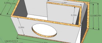
Subwoofer box
A couple of months after the start of assembly, I managed to buy a SONY XPLOD XS-GTX120L subwoofer head, the head parameters are below. Rated power - 300 W Peak power - 1000 W Frequency range 30 - 1000 Hz Sensitivity - 86 dB Output impedance - 4 Ohms Frequency range - 30 - 1000 Hz Diffuser material - polypropylene
Since stores only sold laminated chipboards, and we don’t have MDF at all, we had to choose from what was available. Fortunately, we were lucky with the material. Chipboard from USSR times was perfectly preserved in the attic, thickness 22 mm.
Next, the store purchased self-tapping screws with a length of 50mm (50 pcs.) and white silicone sealant (if available, buy transparent). The box was calculated using the WinISD program. Volume is about 83 liters.
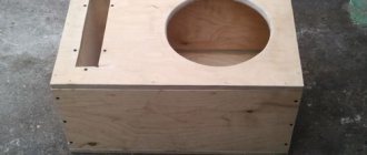
The diameter of the FI port is 14 cm, the length of the pipe is 7 cm. A hole with a diameter of 28 cm was cut for the head. After making all the parts of the box, it was time to assemble it. It is convenient to start assembly by joining the bottom and front of the box. First, holes for the screws were made with a drill (with a small diameter drill), and only then the screws were screwed on. Before this, the fastening points were covered with PVA glue. There is no need to spare glue, so as not to complain about whistling later. I got a pretty good box, I worked as neatly as possible. Finally, the seams were coated with silicone on the inside of the box (silicone has an unpleasant odor, so this work should be done in a garage or outdoors). After assembling the box, I couldn’t resist, put the head where it was supposed to be and turned it on
I cannot convey this in words or even in a video, because it needs to be felt, not heard. You can feel the full volume of the box, the scope of the head, the power and quality of Lanzar, and all this is embodied in pressure on the chest…. It’s impossible to describe this in words, and only then do you begin to understand that everything around you is collapsing and falling apart, the glass is moving on the table by itself, the glass is beginning to “swell” from the pressure. In a word, everything in the house was under a “dose” of vibration.
Next, the box was covered with carpet. Carpet 120x200mm, enough for the entire box.
We sold special glue for carpet, but a can of aerosol costs $25, so we had to use PVA glue. To begin with, I sanded the box; this process took me 4 hours. Apply PVA glue to the already cut carpet. After this, the box needs to be “rolled” over a pre-cut carpet. We wrapped the box, now in order for the glue to dry properly, we hammer small nails along the edges, then after drying they can be removed or left.
Then we cut out the holes for the head and the bass reflex. The head is attached to the box with ten self-tapping screws, this ensures tight contact, no additional gaskets are needed.
The output contacts of the box are made from a connector for the network cable of a computer power supply unit; the manufacturing process is clear from the photographs.
This alternative solution is again caused by a shortage of factory connectors.
It turned out well. A separate hole was cut for it. On the inside, after sealing the wire, the connector hole was sealed with silicone sealant to avoid whistles and unwanted noise.
Total construction costs
Voltage converter: BC557 3pcs - $2.5 TL494 1pc - $1 IRF3205 4pcs - $10 Diodes KD213A 4pcs - $4 Polar capacitors - $10 Non-polar capacitors - $3 Resistors - $2 Chokes and transformers - from old PC power supplies Relays - from a voltage stabilizer
Lanzar amplifier: Transistors 2SA1943 2pcs - $6 2SC5200 2pcs - $6 2SB649 2pcs - $2 2SD669 2pcs - $2 2N5401 2pcs - $1 2N5551 2pcs - $1 Resistors 5 watt - 4 pcs - $3 Other resistors - $4 Non-polar capacitors — 3$ Polar capacitors - 5$ Zener diodes - 2 pcs - 1$
Other amplifiers: TDA7388 2 pcs - $15 TDA2005 2 pcs - $2.5 Resistors - $2 Non-polar capacitors - $4 Non-polar capacitors - $6
Filter block: TL072 1 piece - $1 TL084 1 piece - $1 Non-polar capacitors - $3 Resistors - $2 Regulators 3 pieces - $4
Indicator block: LM324 2pcs - $2 LEDs and everything else - $2
Stabilizer block: Transistors $2 Zener diodes 13 volt 6 pcs - $1.5 Stabilizers 7815 2 pcs - $1.5 Zener diodes 7915 1 pc - $0.7 The rest - $2
AC protection: Transistors - $2 Relays - everything else is free $1 Plugs, sockets and connectors were fortunately in stock
Subwoofer box: screws 50 pcs - $0.5 Sealant 2 bottles - $2
Chipboard - free PVA glue - free Head - $65 Carpet - $15
Results
That's all. I'm pleased with the results, very pleased! It is not possible to buy such an amplifier; amplifiers of similar power cost from $400! Although Chinese manufacturers offer for significantly little money, quality and reliability... In general, the amplifier turned out to be a thrice cheers! Everything works great, all you have to do is buy a car and enjoy your hand-made amplifier, while the amplifier will work at home for now, from a powerful 12-volt power supply.
The author of the project is AKA KASYAN. E-mail E-mail address is protected from spambots. Javascript must be enabled in your browser to view the address.
CORRECTLY CONNECTING A SUBWOOFER TO AN AMPLIFIER
DIY subwoofer box drawings, diagrams, photos and
The subwoofer is connected to the amplifier using a car audio converter (adapter, adapter). This is a small device with a pair of RCA outputs and two pairs of wires, two of which are used to connect a dynamic emitter. The rest of the wires can simply be hidden - they are not needed for now. The line output wires (RCA OUT) must be connected to the amplifier.
The principle of connecting a subwoofer to a single-channel amplifier
To connect a car subwoofer to a mono amplifier, you will need to connect the positive and negative voltage wires from the amplifier to the same terminals of the subwoofer - that's all. Connecting several passive subwoofers is a little more complicated. Their connection is carried out in a parallel or series circuit, but with the obligatory precise calculation of their internal resistance.
The principle of connecting a subwoofer to a two-channel amplifier
In this option, the connection is made using a bridge circuit. This connection technology works great with virtually all two-channel amplifiers, to which you need to add another subwoofer. Here, too, everything is simple - we take the positive wire from one channel, and the negative wire from the 2nd channel and feed it to the corresponding terminals of the subwoofer.
When making this connection, special attention should be paid to the internal resistance of the subwoofer, which should be 4 ohms. In addition, you should take into account that with this option, the output power of both channels is added
If the amplifier has the function of switching mono and stereo modes, then in this case the wires are connected to the positive and negative terminals of one channel. If there is a need to connect two subwoofers to the amplifier, then the speaker cable from them is fed to different channels.
For correct and clear operation of the subwoofer, you should provide an LPF low-pass filter, which will set the upper limit of the low frequency.
The principle of connecting a subwoofer to a four-channel amplifier
The standard connection of a speaker system to a four-channel amplifier is considered to be a scheme with two speakers and one subwoofer.
So, the typical way to connect an audio system to an amplifier would be the option of two speakers and a subwoofer. In this case, the sub is connected to the amplifier via a bridge circuit, and the audio speakers are each connected to their own channel. The peculiarity of this connection is that the speakers must work with the front channels, and the sub with the rear ones. But at the same time, it is possible to connect a pair of subwoofers to different rear channels.
Block diagram of the TDA1557Q chip
Dimensions TDA1557Q
Typical connection diagram TDA1557Q
Schematic diagram of switching on TDA1557 with switch-on delay
A delay chain of 100kOhm, 1kOhm resistors and a 100.0x16V capacitor turn on the amplifier with a delay to eliminate clicks in speaker systems.
Typical wiring diagram TDA1557
Amplifier PCB
DIY simple amplifier based on TDA1558Q
Powerful subwoofer amplifier.
How to make an aqua print on a car with your own hands
Fri 16 Jan 055 Category: Power amplifiers
Do you want to buy a car power amplifier for your subwoofer? There is no need to rush, if your hands grow from the right place and fumble around in electronics, then you can assemble a powerful subwoofer amplifier with your own hands, which is several orders of magnitude better than budget amplifiers in the price category of 100-150 dollars.
The power of the amplifier depends directly on the power source, from our amplifier you can safely remove up to 300 watts of pure power with a 55 Volt power supply in the shoulder, then you can increase the power, but this is not good.
Regarding topology #8212, a completely symmetrical circuit, from input to output, is built on complementary pairs that are as close as possible in parameters, and the amplifier is called a lanzar. There have been numerous conversations about this amplifier on various resources. The main advantage of #8212 is simplicity, quality, reliability and availability of components #8212 - all this makes the circuit universal and easy to repeat at home.
The output stage uses powerful bipolar switches of different conductivity; it is recommended to use keys from Toshiba.
The power switches of the output stage (essentially #8212 current amplifiers) operate in class AB, therefore #8212 30-40% of the initial energy will go into waste heat. For this reason, the keys are installed on the heat sink, but they must be isolated from the general heat sink with mica gaskets.
A 1kOhm variable resistor sets the quiescent current of the output stage. The quiescent current needs to be set on a slightly warmed up amplifier#187
Limiters for powering differential stages are selected based on the supply voltage of the amplifier.
Power supply ±70 V #8212 3.3 kΩ #8230 3.9 kΩ
Power supply ±60 V #8212 2.7 kΩ #8230 3.3 kΩ
Power supply ±50 V #8212 2.2 kΩ #8230 2.7 kΩ
Power supply ±40 V #8212 1.5 kΩ #8230 2.2 kΩ
Power supply ±30 V #8212 1.0 kΩ #8230 1.5 kΩ
The printed circuit board in lay format is attached to the article; no need to mirror it.
To power the amplifier from a 220 Volt network, you need a power supply (mains/switching) with a power of at least 400 watts, taking into account the efficiency of the amplifier.
A diode bridge for a current of at least 8 Amps, in the arm the effective capacity of the capacitor bank is 10,000-15,000 μF with a capacitor voltage of at least 63 Volts, if any, then 100 Volts.
The amplifier works great for wideband acoustics; below are the main parameters of the Lanzar amplifier.
Operation of the UMZCH unit
The power amplifier is built on the basis of the popular U7 chip (TDA2050). This is probably the most common audio amplifier operating in class AB. With a total harmonic distortion of 0.5%, it allows you to achieve a power of about 30 W. Capacitor C8 (1uF) cuts off the DC component of the signal and at the same time represents a high-pass filter at the input. R20 (22k) determines the resistance at the input of the power amplifier.
The feedback circuit is resistors R21 (680R) and R22 (22k), changing their ratio leads to a change in gain, and a decrease in R22 or an increase in R21 causes a decrease in gain. In the datasheet of the TDA2050 chip, the manufacturer recommends that it be more than 24 dB. Capacitor C29 (22uF) cuts off the DC component at the amplifier input. Resistor R19 (2.2 Ohm) and capacitor C32 (470nF) prevent the amplifier from self-excitation. The UMZCH power supply is filtered by capacitors C26-C27 (2200uF) and C30-C31 (100nF). The other two channels work similarly.
Description of devices
The term subwoofer refers to an acoustic speaker or system capable of reproducing sound waves in the frequency range of 20-120 Hz. The work is based on the principle of converting electrical signals from an amplifier into sound. For this, an electromechanical device is used - a speaker, which has a special design that ensures the generation of low-frequency sound signals. To improve the sound, it is installed in a housing with a strictly defined volume. Parts of the housing and speaker suspension should not create extraneous sounds (creaking).
Design features of subwoofers
There are several designs for installing the speaker:
- Open speaker installation or unrestricted acoustic baffle. The element is placed on a box with a large volume. On a car, a similar box is the luggage compartment in cars with a sedan body type.
- Installation in a small closed box. The dimensions of the box impose restrictions on the frequency ranges, cutting off the very bottom.
- Bass reflex housing. In such a device, a channel is used that has certain overall dimensions. The bass reflex is based on the effect of the meeting of waves emitted by the outer and inner sides of the speaker.
- A strip body, which is a bass reflex with an additional bulkhead. The speaker is located inside, on the partition. The sound is transmitted through the bass reflex hole. The design is used to create small-sized devices with improved sound parameters.
- The housing of a passive radiator, which is a combination of active and passive speakers with identical characteristics. The elements operate in antiphase. Due to the distance and dimensions, which are calculated individually for each device, it is possible to obtain clear sound with a low frequency.
Purpose
A car amplifier is designed to increase the sound power of the audio system in the car, as well as the normal functioning of the subwoofer. This device will be useful if the standard speakers do not produce loud enough sound.
Often car radios do not have a special amplifier designed to work with a subwoofer. If you connect a subwoofer directly, the audio quality will leave much to be desired.
Required parts and blocks
There are two options for purchasing the necessary blocks: either assemble them yourself by purchasing the necessary parts, or buy them ready-made. The first option saves money, the second saves time. To assemble a compact low-frequency amplifier with your own hands, you will need 4 blocks:
- Frequency amplifier
- Signal Processing
- Transformer from 12 to 40 V
- Rectifier and switching unit
All blocks are available for sale ready-made. It’s quite easy to purchase them and connect them yourself.
Low frequency amplifier (LF)
First, you will have to get hold of the TDA 7294 board. This is the optimal solution for a low-frequency amplifier. It will cost only about three and a half dollars. The technical characteristics of the board allow it to cope with its functions perfectly. At the output, the board provides 100 watts of power. The only caveat is that the circuit is single-channel, but this can also be overcome.
Video about a DIY subwoofer amplifier
The output transistors of the board must be provided with good cooling. To do this, you will need to bend them towards the board, with the contact (metal) surfaces facing up. Then apply thermal paste to the contact surfaces and place a dielectric film. Install radiators on top. This move will allow you to slightly reduce the size of the radiators to save space in the case.
Signal Processing
The car amplifier is intended for a subwoofer, so only low frequencies need to be extracted from the incoming signal. The power amplifier board is single-channel, so a channel adder is installed at the input to the signal processing unit, which converts a two-channel signal into a single-channel one.
The assembly diagram, drawings and list of necessary parts are on our resource.
Boost converter
Next, you will need a simple transformer with voltage from 12 volts (car power supply) to 40 volts. The ready-made TL494 board is perfect for this role. There are other board options, but for radio amateurs with little experience this is the most suitable option. In addition, this board fits this assembly well in terms of its technical characteristics, creating a powerful signal.
Switching and rectification
To create a subwoofer you will need a transformer from 12 to 40 volts
This block consists of two elements:
- Switching block. Using red and green LEDs, it notifies that the amplifier is ready for operation.
- Rectifier block. Designed to stabilize signals supplied to the control unit
Frame
The finished amplifier, of course, will require a housing into which all the blocks will have to be mounted. Here there is scope for amateur activities. Whether you assemble a plywood body yourself or find a ready-made option is up to you, depending on your own preferences.
The case of a DVD player, for example, is well suited for this role. It is compact, looks beautiful, and the outputs on the rear panel can be conveniently adapted for connection to a car audio system.
A unibody aluminum body would be even more suitable. It will also act as a radiator. The boards heat up during operation, so if the case is not aluminum, but, say, plywood, then you will have to organize a good cooling system. In some cases, it is even possible to install active cooling, but this design works well with several large radiators.
Manufacturing instructions
You can assemble a do-it-yourself subwoofer amplifier after preparing all the main elements. A 12-volt device can be assembled without any problems by connecting all the components and placing them in the housing. Thanks to the voltage of the conversion device (transformer), a small fan can be installed on the device body. Thanks to it, air flow will circulate in the system, which will cool the circuits and protect them from overheating, and therefore premature failure.
When connecting with a block, it is necessary to use wires in cambrics. If the wires come into contact with each other, this can lead not only to the formation of a short circuit, but also to burnout of the constituent elements in principle. The units must be installed in the housing in such a way that air can circulate freely between these components. The circuit must be fixed as firmly as possible, otherwise the 12-volt amplifier made will rattle while driving and when the subwoofer is operating.
Subwoofer connection problems
If you connect subwoofers yourself, problems with its operation may arise. The most common errors are incorrect connections, as well as poor contact or the use of conductors of insufficient cross-section.
Examples of problems that users have encountered:
- After connecting the subwoofer, the power is activated, the “power” indicator lights up, but no sound is played. The reason for this behavior is insufficiently good contact with the masses. It is recommended to install an additional ground cable from the battery. The cable must have a cross-section comparable to the grounding cross-section of the amplifier.
- Some radios are equipped with line outputs designed for installing only an active subwoofer. The passive device is connected via an active analog signal converter. When connected directly, the subwoofer is quiet and intermittent. Using a converter involves connecting the main speakers through an amplifier.
- When an active subwoofer is connected to two RCA signal cables coming from the radio, the volume decreases. Disabling one input restores operation. This is due to the fact that the amplifier has a so-called signal doubler in its design. In this case, it is enough to leave one cable and not use the second.
- The active speaker is installed via RCA tulips. The sound is quiet; when you try to turn up the volume, noises and wheezing occur. The reason may be insufficient wire cross-section or a faulty line output fuse (available on radios from a number of manufacturers, for example, Pioneer).
How to choose
An auto amplifier for a subwoofer is selected both according to the purely technological parameters of the device and according to the available inputs.
The latter are able to switch the entire speaker system as conveniently as possible, obtaining a high-quality result in the form of excellent sound. The main thing to remember is that the subwoofer impedance must be equal to the recommended load resistance of the amplifier. In this case, the latter will operate in nominal modes and will not emit heat at abnormal levels.
To correctly select an amplifier based on power, it is recommended to choose an option that is one and a half to two times less powerful than a subwoofer.
This approach ensures that the speakers will not fail and will operate with minimal distortion. However, the amplifier will have a hard time. To ensure that the device does not fail, it must be placed correctly for good cooling.
The option of choosing an amplifier equal in power to a subwoofer requires some understanding of the operation of speaker systems. The user is not recommended to frequently turn the volume control. It needs to be selected once and so that the sub and amplifier operate at 70-80% of their nominal performance. In this case, all components of the audio system are quite well protected, do not operate at their maximum capabilities, and the risk of overheating is significantly reduced.
The last option, when the power of the amplifier is chosen to be one and a half to two times greater than the nominal value of the sub, is suitable for experienced and thoughtful car owners. In this case, the system parameters need to be finely adjusted.
The option when the volume knob is turned to the limit leads to the inevitable burning of the speakers. Therefore, the output power of the amplifier is selected so that the sub is close to the nominal values. In this version of the balance between the parameters of the amplifier and the subwoofer, the latter is at risk and works almost to the limit.
Another useful component that a subwoofer amplifier is equipped with is its own crossover. It forms the frequency band in which the acoustics operate. There are high-frequency filters and low-frequency filters for rich subwoofer sound.
A good amplifier equipped with a crossover always has a cutoff frequency adjustment. Some models may have a switch to increase the signal power per channel. In this case, the passive subwoofer can only be a speaker, without its own crossover.
Some types of inputs and outputs that a car subwoofer amplifier may have include:
- High Level Input. Used to connect the output stage of the radio amplifier. It is useful if the head unit is not complex and has only a limited number of options for connecting speakers. The signal supplied to the High Level Input interface of the amplifier is characterized by distortion and incomplete frequency response, which is formed by the output stage of the radio;
- Line Input. Connection via this input is recommended. The radio, accordingly, must have Line Out outputs, to which the signal is supplied directly from the primary circuit for generating frequency pulses;
- Bridge. This designates amplifier outputs that can be bridged. In this case, the subwoofer receives power from two channels at once. The connecting terminals that the auto amplifier for a subwoofer with bridge support has are designated accordingly.
Another function of the amplifier electronic circuits, which appeals to a certain audience of consumers, allows you to artificially enhance the low-frequency component of the signal. Grand Bass or Bass Boost can allow for fine tuning, such as frequency band selection or gradual decibel increases in volume.
What to do if you want to do everything from scratch
If you want to mount everything in a unique housing or use old passive acoustics for this purpose, you will definitely need a power amplifier
. If there is an old one lying around somewhere, the issue can be considered resolved. Those who don’t have anything suitable at hand will have to improvise a little. The ideal place where you can find everything is the well-known AliExpress. Here you will find both integrated circuits that are inexpensive and can provide high output power per channel, as well as standard products that can be adapted to solve the task at hand - creating a music center.
Many car enthusiasts have probably thought about using a car radio at home, in the country or in the garage in order to be able to listen to music not only in the car. Several questions arise: is it possible to do this and how to connect the car radio at home yourself?
A good radio usually costs much less than any music center, and with multi-channel outputs, it becomes possible to assemble a full-fledged home theater. Which will have decent sound quality for a modest amount, but you will still need to devote a little of your time to this moment.
Installation
Main amplifier board
The amplifier circuit board diagram is shown below.
A printed circuit board can be made by etching a PCB with a copper substrate with a ferric chloride solution. It is easier to transfer the pattern of the contact tracks onto the board from a glossy sheet of paper on which this pattern is printed using a laser printer. The nuances of this method can easily be found on the Internet on relevant electrical engineering sites.
We solder the parts carefully, removing excess flux. This is especially true for microcircuits. The op-amp chip can be installed via the eight-pin panel.
Remember: overheating of semiconductor elements can lead to their failure!
Inductors L1 and L2 in the output filter of the amplifier are made of enameled copper wire with a diameter of 1 mm, by winding onto a cylindrical core with a diameter of 5 mm. The number of coil turns is 20.
The amplifier chip is installed on the heat sink. It must have an area of more than 600 cm². The role of a radiator can be performed by a car chassis.
After installing all the elements, connect the wires.
Power stabilization and communication unit
In the circuit described above, we used the simplest circuit for powering the amplifier through a battery, however, for more stable operation of the amplifier, you can connect it through a stabilizer. You can assemble this device yourself (a circuit for every taste can be found very easily on the Internet), but the easiest way is to use a ready-made stabilization unit from an old amplifier or buy a new one.
In addition, the stabilization unit allows you to save car battery power.
Discharge is prevented by a relay with a separate REM terminal, operating under a voltage of 12 V. The terminal is installed at the output of the car radio, thanks to which the subwoofer begins to work together with the music device.
To control the operation of the amplifier, you can install an LED in the power supply circuit of the device.
Final assembly of the device
After mounting the board, we complete the final assembly of the amplifier and place it in the housing. The body can be made independently from ordinary plywood using a jigsaw. A diagram of the required dimensions is drawn on plywood, cut out with a jigsaw and secured with sealant.
You can also purchase the case in a store or use an aluminum box, which will simultaneously act as a radiator.
When placing all the parts in the case, you need to ensure free air circulation in it for better cooling of the parts.
The amplifier housing must be securely fastened in the car.
Before installation, it is important to make sure that the power polarity is correct, otherwise the device will immediately burn out.
Safety precautions when connecting the device
When installing a subwoofer and amplifier, you must adhere to the following rules:
- Before starting work, disconnect the battery. It should be remembered that turning off the power may lead to incorrect operation of the airbags. Some types of stock radios require a code when turned on again. It is allowed to de-energize the circuits to which the connection is made by removing the fuse.
- The connection of the wires must be reliable and protected from external influences. The best option is soldering followed by protecting the joint with insulating tape, corrugated pipe or heat shrink.
- Use high-quality wiring with the appropriate cross-section. The event ensures operational safety and improves sound quality.
- The power supply circuit is protected by a separate fuse of the appropriate rating. It is prohibited to use standard fuse-links designed for other current values. Information about the voltage in the power circuit is available in the documentation for the device.
- Additional equipment must be securely fixed and not move when the vehicle moves.
Compliance with safety measures during installation will allow you to operate the speaker systems without the risk of fire or damage to the vehicle.
ULF circuit and board
The diagrams were from the Internet. It worked the first time. There is no need to configure anything - just solder without errors.
UMZCH case - aluminum profile from the door, drilled holes for power terminals, speaker terminal, LEDs, variable resistances.
I screwed it all together, soldered the wires, and put handles on the resistor axis. The top, bottom and side walls, from a Chinese radio - I cut them a little deep and blew them out with paint from a can. It didn't even look bad.
A friend has it in the back of a VAZ-2109 on the shelf, the signal is connected to the rear speakers - the low-pass filter does a good job of dampening the signal if it’s from the radio.
Constant power through a 15 A fuse. And standby mode from the radio.
In the car the subwoofer swings normally, a friend even decided to work on improving the interior from rattling, there is such a vibration from the bass! In general, everything turned out well. It took 2 weekends with breaks to build the amplifier. Good luck to everyone, see you again! Alexey Ivchenko was with you. Novorossiysk.
Source: elwo.ru
Active subwoofer
The active subwoofer is equipped with a built-in amplifier installed in the same housing as the speaker. On the outside of the case there are potentiometers for smooth adjustment of volume or frequency parameters. Thanks to the controls, the user can configure the device in accordance with the sound parameters of the other speakers in the speaker system.
Main characteristics of active subwoofers
Active devices include, for example, the Mystery MSK-12.3 subwoofer, which has the following parameters:
- speaker diameter - 300 mm;
- power in normal mode - 280 W;
- peak power value - 560 W;
- frequency range - from 28 Hz to 2900 Hz;
- sensitivity - 90 dB;
- The Mystery MK-2.80 amplifier is included in the package.
Advantages and disadvantages
Pros of an active subwoofer:
- Possibility of saving space, since the amplifier is located in the same acoustic housing with the speaker.
- Due to the built-in amplifier, the subwoofer has an expanded range of uses.
- The subwoofer housing has separate outputs for installing standard speakers. Thanks to this, a separate acoustic system can be built based on the active device.
- Various body shapes.
- degraded sound parameters;
- the amplifier and device may overheat;
- amplifier power limitation;
- relatively high cost of devices;
- active devices are equipped with simplified housings.
CHAPTER 2. Amplifier housing.
I built TDA7293 amplifiers and purchased an input selector 4 years ago.
I developed the idea for a case, but basically it was a design made of an aluminum front panel and walls and a top cover made of oak lamellas. It was an almost classic design, easy to make, but during the suspension of the project I was so tired of this design, I always had the feeling that I had seen this somewhere many times and had already had my fill. Therefore, in view of the recent “disease” with the end cut of plywood, the following design was invented:
The case is made of a set of plywood rectangular rings, a one-piece removable top cover, the base of the case is an aluminum sheet, the front panel is darkened plexiglass. My amplifier will be placed on a low hanging cabinet, so its rear part is clearly visible from above. I don’t really like all this heap of cables on the back of devices, long connectors, so in the back of the case I made a small recess in which the input connectors of the connected cables will be hidden. Of course, not everything will be completely hidden, but at least it will be better.
This should be the final look:
To make the structure, a sheet of 10 mm sanded plywood was purchased. Half of this sheet was also spent on the bookshelf speakers from my other review.
Since the workshop is very small, cutting a whole sheet of plywood on a sawing table is not possible. I first divide the sheet into 2-3 parts with a jigsaw. We cut 10 rectangular sheets of plywood, measuring 400 mm x 300 mm.
We set aside the top and bottom sheets, and mark and cut out windows in the eight central sheets with a jigsaw. The wall thickness of each ring is 10 mm.
Glue the 8 resulting rectangular rings together. press on top and bottom with the remaining sheets and tighten with clamps. I use PVA glue Moment Joiner Super.
In the lower part, the window in the sheet is somewhat different; there it is necessary to provide a shelf to deepen the rear panel, as well as a slightly larger thickness of the side walls, which will later be milled to fit the aluminum base.
In the main part of the body, on the sawing table we saw off the back wall for the rear panel, and glue the main part of the body to the lower part.
To fasten the top cover, I chose black M4 bolts with an internal hex head. I made the recesses in the cover for the bolt head in the same way as for the bookshelf speakers from another review, using a 7 mm wood drill, and then a 4.2 mm drill all the way through.
On the side of the body, we glue plywood cubes to the walls, into which we then place mustache nuts (they will be shown in the photo below). Also in the photo you can already see the walls of the rear niche. I cut them out from a large piece that was left over from the sawn-off back of the body. Glued it on PVA.
Then we take an angle grinder in our hands, with a Velcro attachment and a grinding wheel with 80 grit, draw the radii of curvatures of the case on the top cover, and perpendicular to the plane of the top cover we actively work on creating curves at the corners of the case. We also sand the transitions between layers of plywood sheets on the walls of the case, since mistakes were made during gluing (in the photo above you can see that the parts shifted during gluing, I saw it too late, I don’t know how I missed it), but an angle grinder with such a wheel will correct any mistakes , fortunately there is a large margin in the thickness of the case walls))
By the way, beforehand, after gluing the 8 plywood rings of the body, I also used an angle grinder and a wheel with 80 grit to level the inner walls of the body to an even, smooth state. When working with 80 grit, there are both advantages - the speed of work - and disadvantages - scratches. More about the disadvantages a little later.
Amplifier base.
We saw a sheet of aluminum, 4 mm thick and dimensions 380x280. We apply it to the lower part of the body and draw radii. We grind the radii with an angle grinder / Dremel.
We apply the resulting base and trace with a pencil along the bottom of the body.
We take a router with a groove cutter in our hands and make a 4 mm recess for our base. It didn’t turn out very neatly, there’s nowhere to put the base of the router, all the work is almost suspended, the router tends to cut itself, we need tools to expand the base of the router.
We try on the base, mark, drill and countersink holes for attaching the base to the body
It is necessary to cut a window under the front plexiglass front panel. We print out the window from the drawing on a scale of 1:1, glue it onto a piece of cardboard, cut it out with a scalpel, and glue it to the body with double-sided tape.
We cut out the resulting window with a jigsaw.
Now we need to trim the edges of the window. We also do this with an angle grinder and a circle with 180 grit. Of course, you can do this with a router, but for me it takes longer, and you need good skill, here again there is not enough space for the sole of the router, and there are a lot of straight sections, without a stop I can ruin it. Using an angle grinder, with careful soft movements, we draw straight lines and window radii.
We try on the top cover and use a compass to draw a semicircle of recess for the future volume encoder button.
For the front panel, I considered different options. It should be dark so that the LCD display of the output selector can be seen through it, as well as the control panels of the selector and TV set-top box, but at the same time, the insides of the amplifier should not be visible. There was an option to order a piece of glass and tint it, but the mounting holes had to be very close to the edges, and it seemed that it would be expensive, but honestly I didn’t find out the price. Plexiglas is easier with it, but there are a lot of reviews that it doesn’t work well with the tint film, bubbles appear. I tried the option with tinting varnish, but it is very cloudy, the inscriptions on the LCD display are very cloudy. So I chose another option. Two thin sheets of plexiglass, between them a piece of tint film, this “sandwich” and screwed to the body. During the search for thin plexiglass, I was offered to immediately cut out the parts according to my drawing, since they still cut with a laser cutter, and for 200 rubles. I received these two parts already with holes.
But in fact, as it turned out, I received the parts not from plexiglass (acrylic), but from transparent PET 2 mm thick.
I received a piece of film from an auto-tinting company as a gift, with a light transmittance of 30%; this turned out to be optimal for a bright image of the output selector screen and hiding the insides of the amplifier.
Since PET is not particularly afraid of the tint film, I simply glued it to one of the parts and covered the second one on top. I placed a few drops of superglue on top at several points so that the resulting glass would not peel off and dust would not get in there.
When fitting the transparent panel to the body, a small problem was identified. The top cover of the case turned out to be slightly curved, it is not visible to the eye, but there is a hump of 1-1.5 mm upwards. Because of this, the upper extreme points of the panel rested against the housing cover, and in the middle there was a gap between the panel and the housing cover. You cannot buy flat plywood from us. There were two solutions: 1. Sand the front panel under the top cover. But PET is a bit viscous material, I was generally afraid of ruining the finished parts. 2. Make a groove in the top cover. I thought that this option was better, simpler, and as a plus I would fix the panel in the upper part, in a groove, relative to the body. You need to make a groove with a router, the groove is only 4 mm, I have a milling attachment for Dremel, but I had to go find it and get it from the closet, unfasten the flexible shaft, put on the Dremel, and screw on the inconvenient bottom nut. I decided that there was too much work for a simple shallow hidden groove and decided to do it by hand like this:
A thin cutter into a flexible shaft, two steel rulers as a limiter for the cutter’s stroke, and with “muscular” control of the depth of entry of the cutter, we quickly make a groove. Problem solved.
Next we move on to the volume encoder knob. I ordered this pen: 4pcs aluminum plastic knob potentiometer knob 48*19mm potentiometer cap Volume knob switch cap Encoder for amplifier. Diameter - 48 mm.
The diameter of the recess for the handle in the body is 50 mm in diameter and 7 mm in depth. We fasten the housing with the top cover to the table with clamps, place the router and make a recess for the encoder handle and try on the handle.
I took the following power button: [1 pc. Colorful Useful Durable 22mm LED Power Push Button Switch Momentary/Latching Waterproof Metal Self Locking Stainless Buy on AliExpress] Thread diameter is 22mm. The button has a high pressure part; when pressed, the finger does not fall further than the front surface of the button. The hole in the body was made with a step drill.
Next, we take a grinder, grinding wheels with 220 grit, and diligently sand the body. We even grind very diligently, because, as it turned out, it is necessary to remove all the defects from the work of the grinding wheel with 80 grit.
In the photo below you can see the body prepared for oil coating. This is already the second attempt, the first one was unsuccessful, the oil “revealed” all the transverse deep scratches from the coarse grain, they are just not visible on the cut of the plywood. I had to remove the oil and polish it more thoroughly.
After final sanding, coat the body with oil. As the first layer I used BIOFA tinting oil. Dark brown color, apply in a thin layer so as not to lose the texture.
Cover the second layer with BELINKA INTERIER oil. It will give the body a golden hue, as well as a pleasant shine, like oil with wax. Apply this oil in two layers, removing excess.
Next, polish the body with a wool wheel.
We fasten the front panel from the inside of the case with small self-tapping screws.
The hole for the encoder shaft was made with a 7mm drill. On the reverse side, the encoder housing is pressed against the front panel. We install the encoder knob and the power button.
The body is ready!
On microcircuits
UMZCHs on integrated circuits (ICs) are most often made by those who are satisfied with the sound quality up to average Hi-Fi, but are more attracted by the low cost, speed, ease of assembly and the complete absence of any setup procedures that require special knowledge. Simply, an amplifier on microcircuits is the best option for dummies. The classic of the genre here is the UMZCH on the TDA2004 IC, which has been on the series, God willing, for about 20 years now, on the left in Fig. Power – up to 12 W per channel, supply voltage – 3-18 V unipolar. Radiator area – from 200 sq. see for maximum power. The advantage is the ability to work with a very low-resistance, up to 1.6 Ohm, load, which allows you to extract full power when powered from a 12 V on-board network, and 7-8 W when supplied with a 6-volt power supply, for example, on a motorcycle. However, the output of the TDA2004 in class B is not complementary (on transistors of the same conductivity), so the sound is definitely not Hi-Fi: THD 1%, dynamics 45 dB.
Audio amplifiers based on TDA chips
The more modern TDA7261 does not produce better sound, but is more powerful, up to 25 W, because The upper limit of the supply voltage has been increased to 25 V. The lower limit, 4.5 V, still allows it to be powered from a 6 V on-board network, i.e. The TDA7261 can be started from almost all on-board networks, except for the aircraft 27 V. Using attached components (strapping, on the right in the figure), the TDA7261 can operate in mutation mode and with the St-By (Stand By) function, which switches the UMZCH to the minimum power consumption mode when there is no input signal for a certain time. Convenience costs money, so for a stereo you will need a pair of TDA7261 with radiators from 250 sq. see for each.
“Super economical” in terms of power supply TDA7482, on the left in the figure, operating in the so-called. class D. Such UMZCHs are sometimes called digital amplifiers, which is incorrect. For real digitization, level samples are taken from an analog signal with a quantization frequency that is no less than twice the highest of the reproduced frequencies, the value of each sample is recorded in a noise-resistant code and stored for further use. UMZCH class D – pulse. In them, the analogue is directly converted into a sequence of high-frequency pulse-width modulated (PWM), which is fed to the speaker through a low-pass filter (LPF).
Class D pulse audio amplifiers on microcircuits
Class D sound has nothing in common with Hi-Fi: SOI of 2% and dynamics of 55 dB for class D UMZCH are considered very good indicators. And TDA7482 here, it must be said, is not the optimal choice: other companies specializing in class D produce UMZCH ICs that are cheaper and require less wiring, for example, D-UMZCH of the Paxx series, on the right in Fig.
Among the TDAs, the 4-channel TDA7385 should be noted, see the figure, on which you can assemble a good amplifier for speakers up to medium Hi-Fi, inclusive, with frequency division into 2 bands or for a system with a subwoofer. In both cases, low-pass and mid-high-frequency filtering is done at the input on a weak signal, which simplifies the design of the filters and allows deeper separation of the bands. And if the acoustics are subwoofer, then 2 channels of the TDA7385 can be allocated for the sub-ULF bridge circuit (see below), and the remaining 2 can be used for MF-HF.
4-channel UMZCH on a chip
Photos of printed circuit boards
After assembly, the TDA1562 chip itself is tested not on a 50-amp battery, but at home with an ATX power supply. It works without problems with a 4 Ohm load, and also copes well with a 2 Ohm load. Of course, one cannot expect miracles from such a simple design, but of course this chip is worthy of its price.
Double-row low-pass filter (12 dB/octave) with an adjustable upper cutoff frequency from 20 to 200 Hz, which allows you to carefully test and select the operating frequency of the subwoofer. Initially, adjustment was made to 100 Hz, but changing the dual potentiometer value from 2x10K to 2x20K increased this range. In general, this is a typical filter built on the basis of an operational amplifier such as NE5523, TL072, or LM358. The filter is powered through a resistor and a large 4700uF/16V capacitor shunted with a 100nF capacitance, which prevents the passage of high-frequency interference. In addition, power from the BAT point passes through a 10 A fuse. Make sure this fuse is of the correct size. The diode protects the entire circuit from incorrect polarity of the supply voltage; it must be stronger than the current of the fuse used. In the diagram it is 1N4004, but you need to solder a higher power diode (for example, from an ATX power supply).
The amplifier circuit will load the battery with a current of up to 8 A, therefore, the connecting cable must be at least 2.5 mm square. We can get mass from any point, for example, metal parts of the trunk. The microcircuit requires cooling; for this it is necessary to attach a radiator to it. The amplifier turns on automatically along with the car player; for this we use the MODE input. So when the radio is off, so is the subwoofer. After the UMZCH has been successfully assembled and tested, we move on to the second part - making the subwoofer box.
Headphone Amplifier
A headphone amplifier is most often made by hand for two reasons. The first is for listening “on the go”, i.e. outside the home, when the power of the audio output of the player or smartphone is not enough to drive “buttons” or “burdocks”. The second is for high-end home headphones. A Hi-Fi UMZCH for an ordinary living room is needed with dynamics of up to 70-75 dB, but the dynamic range of the best modern stereo headphones exceeds 100 dB. An amplifier with such dynamics costs more than some cars, and its power will be from 200 W per channel, which is too much for an ordinary apartment: listening at a power that is much lower than the rated power spoils the sound, see above. Therefore, it makes sense to make a low-power, but with good dynamics, a separate amplifier specifically for headphones: the prices for household UMZCHs with such an additional weight are clearly absurdly inflated.
Headphone amplifiers using transistors and microcircuits
The circuit of the simplest headphone amplifier using transistors is given in pos. 1 pic. The sound is only for Chinese “buttons”, it works in class B. It is also no different in terms of efficiency - 13 mm lithium batteries last for 3-4 hours at full volume. At pos. 2 – TDA’s classic for on-the-go headphones. The sound, however, is quite decent, up to average Hi-Fi depending on the track digitization parameters. There are countless amateur improvements to the TDA7050 harness, but no one has yet achieved the transition of sound to the next level of class: the “microphone” itself does not allow it. TDA7057 (item 3) is simply more functional; you can connect the volume control to a regular, not dual, potentiometer.
The UMZCH for headphones on the TDA7350 (item 4) is designed to drive good individual acoustics. It is on this IC that headphone amplifiers in most middle and high-class household UMZCHs are assembled. The UMZCH for headphones on KA2206B (item 5) is already considered professional: its maximum power of 2.3 W is enough to drive such serious isodynamic “mugs” as TDS-7 and TDS-15.
For a snack
In conclusion - a complete exotic, headphone amplifier... on tubes, see figure, and only one channel, the other requires the same rarities. Although this amplifier implements almost all tube rituals (except, perhaps, a fixed bias from batteries), it is not only and not so much a tribute to vacuum audiophiles: when listening to the TDS-7 through this amplifier, the sound is through-through analogue, compared to the KA2206B, improves noticeably.
Tube headphone amplifier
labavto.com
Every car owner knows that good audio systems are quite expensive. The price of just one of the main elements that allows you to produce high-quality sound - an amplifier - can be more than a hundred dollars. Therefore, many connoisseurs of high-quality sound are thinking about how to make a music amplifier for a subwoofer with their own hands. We will talk about this below.
Inspection and troubleshooting of the power supply.
If you purchased a new power supply, then you can safely skip this point.
Turn on the computer power supply to check the output voltage. Make sure that when current is applied, the cooler (fan) installed on the rear starts spinning.
Open the lid and look inside the unit, there will probably be a lot of dust there, wipe everything thoroughly with a dry cloth, you can also use a vacuum cleaner. After cleaning off dirt and dust, carefully inspect the board contacts for defects and cracks in the solder.
We carefully inspect the capacitors located
on the board, if they are swollen, this indicates that the block is faulty, or it does not have long to live. (capacitors are circled in red in the picture above) Swollen capacitors must be replaced
This process requires caution, since high-voltage capacitors contain a residual current charge, which can cause a slight but very noticeable electric shock. Assemble the power supply and start connecting
CHAPTER 4. USER INFRASTRUCTURE.
The entire music collection, as well as movies, are stored on a small home server, in the form of an old Lenovo Thinkpad X61 with Debian Stretch installed.
A server with 3TB of disk space is used as file storage (with access from all devices via NFS), torrent downloader, UPNP server, Nextcloud and Timemachine for Macs.
Both Raspberry Pi and Android TV box are connected to a common home network via Ethernet, with file access via NFS (Kodi on the TV box).
For Raspberry Pi I used different distributions (Volumio, Runeaudio, Moodeaudio), and bare Raspbian with an MPD server installed, but finally settled on the Moodeaudio distribution (www.moodeaudio.org). This distribution seemed to me the most stable, actively developing, and with many working bonuses out of the box.
For remote playback on Raspberry Pi, you can use the following schemes:
— control playback of a music collection from the server via the Moodeaudio web interface:
— control playback of a music collection from the server via the Android application MPDriod
- using Raspberry Pi as a UPNP renderer from the J.River Media Center application (which I use as the main, most adequate application for Macos, for managing the music collection and synchronizing with storage devices for music in the car):
and through the Android application BubbleUPNP. I also sometimes use this application to remotely access my music collection on my home server.
I use MinimServer on Debian as a UPNP server.
I also really like the Cantata application, for accessing the MPD server on Moodeaudio, with downloadable covers and your own playlists. It is available for different platforms and is also being actively developed by the author:
Well, the simplest thing is to use the Raspberry Pi as an Airplay receiver and send a stream from Macos and iOS devices directly. We use this function periodically.
A very short video of using the device:
How to make a simple sound amplifier
The circuit diagram of the author's version of a simple sound amplifier is shown on the radio chip website, see Fig. 1. It is useful for beginning radio amateurs to know how a bridge UMZCH differs from a traditional one with two output transistors, which are widely used in household serial radios, tape recorders, televisions and other sound-reproducing equipment.
The advantage of a conventional audio amplifier is the use of only two transistors in the output stage, while in a bridge UMZCH this requires four transistors. The disadvantage of the output stage on two transistors, when using a unipolar power supply, is the presence of a constant voltage at the output of these transistors, which requires a large-capacity electrolytic separating capacitor to connect the speakers.
Required equipment and components
So, in addition to the above microcircuit, we will need:
- operational amplifier TL 072 (can be replaced with TL 062, TL 082 or 4558 microcircuits);
- resistors with a power of 0.25-0.5 W;
- electrolytic capacitors (new!);
- non-polar capacitors - film;
- insulated wires;
- thermal paste;
- radiator with a dispersion area of at least 600 cm²;
- single-sided PCB sheet.
It is also recommended that the circuit be powered through a 10 A fuse and a choke, which can be “borrowed” from an old radio (read about what the choice of a car radio should be based on).
Of course, we can’t do without a soldering iron, solder and some skill in handling all this.
Do-it-yourself amplifier with a power of 4x22 W
If the transformer is installed not only for the power supply, it must be separated from the amplifier's power supply. In our particular case, we made an amplifier with our own hands, which will be used with a home computer. That is why it was decided to connect the computer's power supply to the amplifier.
For this, a special relay was used, which made it possible to switch the amplifier's power supply and the computer's power supply. There is no difficulty in performing this work. When planning the manufacture of an amplifier, you must remember that high-quality powerful amplifiers allow you to obtain high-quality sound, but at the same time there is a problem with cooling the device.
The optimal voltage for DIY home amplifiers is 15 volts. It is this voltage indicator that we recommend that you adhere to when making an amplifier. Let's move on to assembling the amplifier. The assembly diagram is more than primitive, which makes it possible to perform it by hanging installation.
We mount the microcircuit on a radiator, for which it is recommended to use a special thermal paste, which will improve heat transfer performance. To prevent extra contacts from interfering with soldering, you can bite them off with wire cutters. We bend the necessary contacts and, in full accordance with the diagram, solder them with a soldering iron.
To increase the reliability of the connection, it is necessary to use special hot-melt adhesive, which will also avoid the risk of a short circuit between the wires and capacitors. It is necessary to use such hot-melt adhesive after all elements have been soldered to the microcircuit.
At this point, our sound amplifier is completely ready. You can connect it to a power source and conduct test listening. All you have to do is decorate the chip, which will give it a neat appearance. In this case, we can recommend that you use a case from an old CD drive, which can easily accommodate an amplifier chip and cooling radiators.
We attach everything with hot melt glue and install a small LED. Connect the LED to the power supply and remove all the wires inside the case. You can also use metal containers as a housing for the amplifier. In such a case, the cooling rate will be even better than when using a case from an old drive.
Just remember to make ventilation holes in the metal case. The DIY amplifier is ready and you can connect it to a sound source. As you can see, manufacturing such an amplifier is not difficult and has minimal cost.
The cost of the radio components used in the power amplifier
- Diode bridge 1000V 8A 20 rubles.
- Thermal paste 40 rubles.
- Thermal paste 40 rubles.
- Capacitors (0.22 uF 4 pcs. 0.1 uF 2 pcs.) 35 rubles.
- Capacitor 25V 6800uF 38 rubles. 1 PC.
- TDA1558Q microcircuits – 80 rubles. 1 PC.
Additional Tips
Experienced radio amateurs can achieve even cleaner sound from the amplifier if they create the circuit themselves. It is quite difficult to do this without auxiliary tools.
To avoid confusion, it is recommended to use the Sprint Layout program. It has the following functions:
- designing circuits of low and medium complexity;
- wiring design;
- viewing models in three dimensions;
- ability to create a parts library.
You can download and install a Russified program with additional functionality for free. To do this, you should look for version 6 of the software (not the official one, but the translated one). It is compatible with all English versions up to the fifth.
The program will help you create visual plans that are much more useful in practice than photos of homemade sound amplifiers and their circuits.