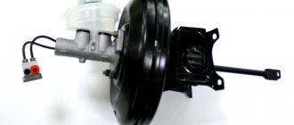
A vacuum brake booster is required to make it easier to press the brake pedal. It can only work when the car engine is running. This happens because when the engine is running, the filter housing begins to suck in air, which enters the intake manifold. At the same time, air is taken into the combustion chamber and goes into the vacuum chamber, which is why it begins to work.
Payment via PayPal
After selecting payment via PayPal, the PayPal payment system will launch, where you need to select the payment method: bank card or PayPal account.
If you already have a PayPal account, then you need to log into it and make a payment.
If you do not have a PayPal account, and you want to pay using a bank card via PayPal, you need to click on the “Create an Account” button - shown with an arrow in the picture.
PayPal will then prompt you to select your country and provide your credit card information.
After specifying the information required to make the payment, you must click on the “Pay Now” button.
Engine power system design
The vehicle's power system is designed to store fuel reserves, purify fuel and air from foreign impurities, and supply air and fuel to the engine cylinders.
The power system consists of a fuel tank, a fuel module, a fuel filter, a fuel rail with injectors, an air filter, fuel lines, air ducts, a throttle assembly, a receiver, and a gasoline vapor recovery system. The air entering the engine cylinders is cleaned of dust by an air filter. Air filter
installed in the engine compartment on three rubber supports. The filter element is replaceable and made of special paper. To prevent contaminated air from leaking into the intake tract, there is a sealing edging at the top of the element. To replace the filter element, the filter cover is removable. The purified air passes through the mass air flow sensor (for more details, see “Engine Management System”) through the air duct to the throttle valve.
Throttle valve
regulates the amount of air entering the engine cylinders. The damper drive from the gas pedal is a cable drive. The damper rotates on an axis in the housing (pipe). The throttle body is secured to the intake module flange with studs. The housing has a channel for coolant. The channel is connected to the cooling system by rubber hoses. Circulating coolant through the throttle body prevents the body's internal air cavities from freezing in the winter. The housing contains fittings for connection to the adsorber and the engine crankcase ventilation system.
The throttle body, with the throttle position sensor and idle speed control installed on it (for more details, see “Engine Management System”) form the throttle assembly.
Throttle assembly:
1 - throttle valve drive sector; 2, 4 — fittings for connection to the engine cooling system; 3 — crankcase gas outlet fitting; 5 — throttle position sensor; 6 — idle speed regulator; 7 — fitting for connecting to the adsorber; 8 — throttle valve; 9 — throttle body pipe
The fuel supply is stored in a tank with a capacity of 43 liters. Fuel tank
steel, welded from two stamped parts.
The tank is suspended from the bottom of the car on two steel clamps. The filler neck of the fuel tank is located on the right side of the vehicle and is closed with a plug. Fuel from the tank is supplied by an electric
submersible fuel pump
The pump is installed in the fuel tank. To access the pump, there is a hatch with a cover in the bottom of the car under the rear seat cushions.
A strainer is installed on the inlet pipe of the fuel pump, which traps small solid particles of debris that enter the fuel tank along with gasoline. The pump is supplied with voltage at the command of the ECU (see “Engine Management System”) when the ignition is turned on. If no attempt is made to start the engine, then after 2-3 s the ECU will turn off the fuel pump.
Fuel pump:
1
—
protrusion for attaching a mesh filter; 2 — fuel intake pipe for connecting a strainer; 3 - body; 4 — electrical connector block; 5 - outlet (discharge) pipe for connection to the fuel module cover with a corrugated tube
Comment. On a car with an MP7.0 ECU, when you first try to start the engine after connecting the battery, the fuel pump can only be turned on simultaneously with the starter. In the future, the fuel pump will operate as on cars with other types of ECUs. However, after turning the ignition on three times in a row without starting the engine, the fuel pump will only be turned on simultaneously with the starter
From the pump, gasoline flows through the corrugated tube of the fuel module into the fuel line and then into the fuel filter, where the fuel undergoes more thorough cleaning.
Fuel filter
— paper, installed in a metal non-separable case.
The purified fuel flows through the fuel line into the fuel rail.
Fuel filter for engines 21124 and 21114:
1 — inlet pipe; 2 - body; 3 — fuel flow direction arrow (painted on the filter housing); 4 - outlet pipe
Comment.
The fuel filter of engines 2112 and 2111 has threaded connecting pipes.
Fuel rail
holds four injectors and supplies fuel to them. The connection between the ramp and the injectors is sealed with rubber rings. The ramp is secured to the cylinder head with bolts.
Let's summarize
As you can see, the operation is not difficult
It is important to do everything consistently and carefully. The work will take you about an hour
While a trip to a car service center will take much more time. For a better understanding of the process of replacing the vacuum brake booster of VAZ 2110, 2111, 2112, watch this video:
When I pressed the brake pedal, a hissing sound appeared in the cabin and the engine began to choke. All the symptoms of a faulty VUT. This spare part costs 1070 rubles DAAZ - Lada Detail. Brake fluid 130 rubles.
Actually1. unscrewed the casing bolts 2. unscrewed the wiper and half of the frill3. removed the upper pipe of the stove on the expansion tank4. moved the tank5. pulled out part of the engine compartment trim6. ratchet extension head 17, unscrewed 2 nuts of the brake master cylinder7. moved into the interior there are 4 nuts, head 13, two at the top of the brake pedal and two at the bottom. It was not convenient at all, I had to tinker.8. removed the plug from the brake fluid reservoir.9. I moved the brake cylinder with the reservoir to the air filter, only carefully since the hoses are metal so as not to damage them, and disconnected the hose from the VUT.10 valve. took the VUT and pulled it out along with the brake pedal.11. I removed the bracket, pulled out the bolt, it holds the pedal and the vut.12 mount. unscrewed two 17 nicks with which the VUT is rotated to the pedal mount. 13. took a new VUT, inserted it, aligned it, inserted the bolt, hooked the bracket, two nuts for 1714. installed everything in the reverse order 15. The installation was successful, everything worked properly, and in the end it was a disappointment when trying to unscrew the fittings for bleeding the brakes, the right rear part was torn off inside, the right front part was torn off, but the left part was unscrewed without problems.
Found something to do in the future tense Issue price: 1,200 ₽ Mileage: 165,300 km
Welcome! Vacuum brake booster - designed to make the brake pedal much easier to press, it only works when the engine is running, but when the engine is turned off, the vacuum booster will not work, all this is due to the fact that when the engine starts, the air filter housing begins to suck in air from the environment and it enters the intake manifold, air is taken from the manifold a little and goes into the vacuum chamber and therefore it starts to work only when the engine starts.
Note! To replace the brake booster, you will need: A set of all kinds of wrenches, as well as a couple of screwdrivers, and also for this task, a socket head and a wrench will be very convenient!
- Replacing the vacuum brake booster
- Additional video clip
Where is the vacuum brake booster located? It is screwed to the car body with four nuts, or rather not the itself, but its bracket, the vacuum booster itself is secured to this bracket with two nuts, but they are easiest to remove as an assembly, i.e. unscrew the four nuts that secure the bracket to the body and then remove them, and when the vacuum booster with the bracket is in your hands, you will need to unscrew the two nuts and separate them from each other, but we will talk about this later in this article, a little lower .
When do you need to change the vacuum brake booster? If the brake booster fails, a hiss may appear when you press the brake pedal, and the speed may also go up and then down, in addition, the brake pedal will become difficult to press (This is equivalent to the fact that the car is turned off) basically this is there are all the symptoms that indicate that the vacuum booster has failed, it does not always happen that they all appear together in the car, but a couple of them will still appear when the vacuum booster becomes unusable (the main ones most likely, namely, tight brake pedal and floating speed).
Note! By the way, the vacuum booster can be checked for serviceability as follows: With the engine off, press the brake pedal 5 times and when the last press is made, hold the pedal to the floor, immediately after which start the car, if the pedal falls a little, this will indicate that that the vacuum booster is fully operational!
Replacement process
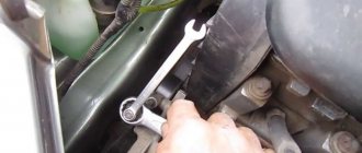
- Remove all screws that secure the thermal protection.
You need to unscrew a bunch of bolts, which are indicated by arrows. And remove the protection.
- Unfasten the belt securing the expansion tank in the cooling system.
- Place the tank on a level place and do not disconnect the hoses from it, as the liquid will leak out of the system.
Similar work will need to be carried out on the right side of the car. There you will have to remove the windshield washer reservoir.
- After this, disconnect the wires from the brake reservoir cap.
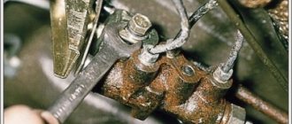
- Disconnect the vacuum check valve and unscrew the two nuts that secure the brake master cylinder. After this, the cylinder should be moved to the side so as not to damage the brake system pipes on it.
Two nuts securing the master brake cylinder to the VUT Move the reservoir of the master brake cylinder to the side
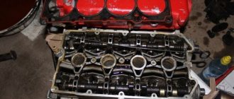
Then you should move into the cabin and unscrew the four nuts that secure the bracket on which the amplifier is located.
The bolts are marked with arrows. You can remove it together with the pedal, then disconnect the chip on the brake pedal. Unscrew the rod from the brake pedal if you want to remove only the booster
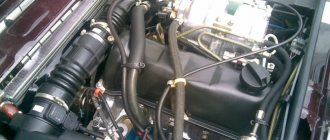
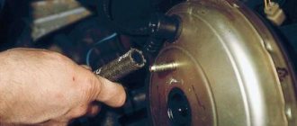
Then again you need to go into the engine compartment and remove the intake manifold hose.
Removing the VUT intake manifold hose
None At this point the work can be considered completed.
Master brake cylinder
Now let's talk about the master brake cylinder on a VAZ 2110 car. If you do not want to allow the brakes to fail while driving, they should be checked periodically, and if problems arise, take appropriate action immediately.
A common reason for replacing the master brake cylinder of a VAZ 2110 is precisely the fact that the brakes are lost.
Symptoms of a problem
Of course, brakes can completely lose their effectiveness for various reasons, but now we are talking specifically about the master cylinder. If the reason lies therein, then it can be determined by the following signs:
- The master cylinder shows signs of brake fluid leakage;
- The pedal has an idle motion, that is, when it is pressed, no force is created;
- The brake pedal simply won't press.
Replacement
To repair the master brake cylinder of a VAZ 2110, you will need to first disassemble it and then install a new element.
The most difficult process is disassembly. Therefore, let's talk about it in more detail.
Carefully disconnect the master cylinder from the pipeline. Disconnect the block, which is equipped with wiring, from the emergency brake fluid indicator. The connection to the “ten” is made by terminals. Cover the pipe and assembly openings with something to prevent brake fluid from leaking. It will pollute the interior space, which is undesirable. Now remove the cylinder along with the reservoir. To do this, simply unscrew the fastening nuts that connect the element to the vacuum booster. After removing the brake fluid level sensor, drain the brake fluid present from the cylinder and the cylinder itself. If there is no serious need, you should not remove the tank. But for complete assembly, the tank is removed and then installed in place in strict order. Before reassembly, each element is washed with purified brake fluid.
A good alternative is isopropyl alcohol. Do not forget to dry the parts with a compressor and wipe with a clean, dry cloth. Carefully avoid contact of the main cylinder with fuel or kerosene. Pay special attention to the O-rings. If you wash them with special alcohol, do not keep the rings in this liquid for more than 20 seconds.
After processing, immediately dry and wipe the seals. Treat the surface of the piston and mirror to remove all rust. When replacing the master cylinder, new O-rings must be installed, regardless of their current condition. Check the elasticity of the piston springs under load. Refer to the VAZ 2110 repair manual, which indicates the appropriate loads and forces for testing. When free, the length of the spring should be 59.8 millimeters. If the indicator deviates from the norm, be sure to replace the springs.
How to make a replacement?
Replacement is carried out using a set of keys and screwdrivers. The vacuum brake booster is located under the hood, so work can be done in the garage or outside. The replacement takes place as follows:
- First you need to disassemble the wall of the VAZ 2110 engine compartment, then remove the frill. This element is attached using a seal and upholstery;
Important! The most unpleasant moment in dismantling the vacuum brake booster is unscrewing the four nuts in the interior. To get to them you will have to remove several elements of the dashboard.
Vacuum amplifier
VAZ 2115 vacuum booster replacement
As you know, the brake system of a current car is a rather complex structure that combines several components and mechanisms. Indeed, there are a lot of details and components here.
The vacuum amplifier or VU fails and there are underlying factors for this. On the other hand, thanks to the ingenious invention of engineers, this unit is made in such a way that it is quite easy to repair, even in your own garage.
Simple in design
Features of a vacuum vehicle
Replacing the vacuum booster VAZ 2115
Let's look at the most important features of this type of vehicle:
- As a rule, the booster is installed on a car near the main brake cylinder.
- The amplifier housing is divided into two components: vacuum, which is located on the side of the main cylinder and atmospheric, located near the brake pedal.
VU design
A specially designed air intake manifold is needed to ensure that the vacuum chamber has a source for vacuum. It is connected to the camera through a special element.
Intake manifold VU
- When the engine stops, the manifold and valve are automatically separated from each other. Thus, the amplifier can only function when the car engine is running. And in other cases, in fact, it is not needed.
- When any breakdown is observed, the vacuum booster is also disconnected.
- A special monitoring valve is responsible for connecting the atmospheric chamber with the vacuum chamber. After the driver applies the pedal, this valve will begin to monitor the connection with the atmosphere.
- The pushrod, which is installed nearby, is connected directly to the pedal. Its main task is, in turn, to move the follower valve.
VU scheme
- There is another part in the vacuum brake system. This is the diaphragm of the connection body, which is located on the side of the vacuum chamber and is connected to the cylinder rod. Thus, there is a non-stop effect on the brake fluid (brake fluid), carried out using a piston directly on the working cylinders.
- The mechanism also has a return spring, the task of which is to return the diaphragm to its initial position.
Detailed operation diagram of the VU
Checking the amplifier status
Even an inexperienced motorist can understand that the VUT is out of order, since pressing the pedal will require much more effort. Replacing the VUT VAZ 2110 is required if a hissing sound is heard when you press the pedal, and the pedal becomes too tight. The device should be checked with the engine turned off: the driver should press the pedal several times and then hold it in the depressed position. Next, you need to start the engine, and if the brake pedal goes down to the bottom of the car without strong resistance, then the unit is working properly.
If the pedal is pressed with difficulty, then there is a defect in the unit. To avoid having to disassemble the system once again, it is recommended to check the booster check valve and vacuum hose - these elements must be sealed and not damaged. The most common defects are:
- Spring damage.
- Hose break.
- Diaphragm rupture or crack.
Article on the topic: Replacing front and rear brake pads on a VAZ 2109
Recommendations
If the VUT fails on a VAZ 2110, the replacement can be done with your own hands in a regular garage
However, after replacement it is important to check the amplifier. The fact is that sometimes even a new amplifier can be faulty, and errors are often made during reassembly
For this reason, it is recommended to additionally check the VUT for air leaks. To diagnose, you need to start the car engine and press the brake pedal all the way, then turn off the engine.
If after 30 seconds the pedal does not deviate from the fully depressed position, this will indicate that the amplifier is OK. If, after releasing the pedal, it begins to return back under the influence of the return spring, then this indicates an increase in pressure inside the working amplifier. In turn, this is a malfunction of the vacuum booster.
What to do with a faulty device
Now we have learned how to check the brake booster. What to do next? At a service station, they will most likely tell you that it would be more advisable to replace this system with a new one. But a faulty device can either be repaired and adjusted, or some components can be replaced during the reconstruction process. And only in special situations does the entire mechanism need to be replaced.
Vacuum brake booster disassembled
Adjustment and repair
When adjusting the vacuum assistant, the free movement of the brake pedal is adjusted. To set it correctly, we adjust the length of the rod. Using the adjusting bolt, check the gap/protrusion. It is important to correctly adjust the position of the bolt itself - this will allow you to find the exact moment of opening/closing of the valves.
Repair and replacement
A leaky hose in a car with a gasoline internal combustion engine or a pump in a diesel car needs to be changed. If the holders are loose, they must be tightened. If the rubber gaskets of the check valve are worn out, we use a repair kit, after making sure that the problem is only in them and that other components of the VUT are not damaged. In principle, the check valve can be replaced with a new one, since it is relatively inexpensive, and its repair is quite labor-intensive.
More serious problems discovered by the node check should be addressed to specialists. Having spent some amount of money, you will be confident in the safety of yourself and your passengers. In addition, after reconstruction, it is necessary to synchronize the wheels when slowing down, check the anti-lock braking system and the exchange rate stability system. And this is carried out at a diagnostic stand using special technical means.
Source
If you notice that you have to apply significant force to slow down or stop the car, and the brake pedal travel when the engine is running has decreased and become stiffer, you need to diagnose the vacuum brake booster (VBS). Replacing the VUT, if necessary, can be easily done with your own hands.
Before checking the vacuum brake booster, you must make sure that the hose connecting its valve to the intake manifold is tight. This can be done by visually checking its integrity or by attempting to pump air using a compressor with a pressure gauge into a hose or rubber bulb that has been removed and plugged on one side.
How to remove the vacuum seal on a VAZ 2110
If self-diagnosis suggests a malfunction of the amplifier, then removing the vacuum seal on a VAZ 2110 is a matter of technique. To begin with, you should prepare a metalworking tool. It's good if there is a service kit. In his absence, you need to prepare the keys: three heads: 10 mm, 13 mm and 17 mm, a wrench with an extension, a pair of Phillips and slotted screwdrivers, and pliers.
Then, you can remove the vacuum seal on the VAZ 2110 in the following order:
- We disconnect the negative terminal from the battery (these are the rules of plumbing);
- We unscrew the upper screws that secure the soundproofing material to the engine shield;
- Disconnect the rubber band securing the expansion tank;
- Without disconnecting the connections of the coolant hoses, we move the tank to the side;
- Now it becomes possible to move back the sound insulation;
- Disconnect the terminal from the fluid level sensor on the brake cylinder cover;
- Holding the return valve, pull out the air supply hose from it;
- Next, you need to disconnect the vacuum seal and the brake cylinder. To do this, you need to unscrew the two outer fastening nuts;
- In order not to disconnect the brake pipes, smoothly moves the unscrewed cylinder away from the booster;
- Let's go to the salon. On the shield, along the perimeter of the brake pedal, we find four studs that are secured with nuts. We unscrew them;
- Then we disconnect the finger that connects the pedal and the amplifier pusher rod;
- After this, you can return to the engine compartment and remove the unscrewed unit.
With the amplifier removed, the pedal bracket will remain. It is secured with two nuts. It should be removed and reinstalled on a new vacuum unit for your VAZ 2110. Assembly occurs in the reverse order. After you managed to change the vacuum seal on a VAZ 2110, you do not need to bleed the brakes, because the brake pipes were not disconnected.
Step by step replacement
1. Open the hood and disconnect the connector that goes to the brake fluid float in the reservoir.
2. Now we need to remove the brake master cylinder. There is no need to unscrew the tubes.
Using a wrench and a 17mm socket, unscrew the two nuts securing the cylinder and move it a little to the side.
Be careful not to drop the nuts into the engine compartment. There are also washers installed under the nuts; don’t forget to remove them.
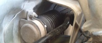
3. Disconnect the hose from the vacuum booster.
4. Next we go to the salon.
5. The studs from the vacuum booster go into the cabin and are screwed in with nuts, of course, in the cabin.
6. Using a wrench and a deep socket, unscrew the four nuts securing the vacuum booster.
7. Remove two wires from the “frog” of the brake light.
8. Remove the vacuum booster along with the bracket and brake pedal.
Functionality check
This instruction will be relevant when checking the vacuum booster on VAZ models from 2113 to 2115. So the technique is clearly universal.
- Press the brake pedal all the way to the floor about 4-5 times. In this case, the engine should not be started. Due to these presses, you will create equal pressure in two sections of your vacuum booster. The valve will report problems as soon as you start pressing the pedal. If you hear squeaks while pressing, this indicates a serious malfunction.
- Once the pressure is even, start the engine while keeping the brake pedal to the floor. If the brake booster system is working properly, then the pedal will rise by itself after the engine is started. If this does not happen, then you will definitely have to face repair work.
- If the check shows problems with the amplifier, do not forget to additionally check the quality of the hose fastening and the condition of the flange. When the mount is abnormal, this may result in the brake pedal not lifting.
Sometimes poorly fixed fasteners cause quite expensive and actually unnecessary repairs or replacement of the vacuum booster. Conduct a preliminary check so as not to complicate your life.
When to change the amplifier
Brakes are a whole system that consists of many elements. Each of them must function correctly and efficiently.
In addition to checking the vacuum booster itself, you should inspect the condition of the brake fluid pipes, make sure there are no brake fluid leaks, and look at the current condition of the brake pedal.
If no faults were found in the braking system, you can think in more detail about the issue of replacing the vacuum booster.
There is no point in repairing the element. It's easier to start replacing right away. The functionality of the car and the power that your engine is capable of producing depend on the quality and timeliness of the work performed. Lack of power negatively affects the speed and comfort of movement around the city and beyond.
Replacement
To replace a vacuum booster you will need a certain set of tools and materials. It includes:
- Screwdriver Set;
- Pliers;
- Socket wrench for 13 and 17 millimeters;
- Special wrench for brake pipes;
- New plugs;
- New fittings.
Replacement procedure
Let's get straight to work.
- Removing the vacuum booster can be difficult due to the brake cylinder. Therefore, we advise you to remove it first. Another option is to disconnect the pipes from the brake cylinder and move them to the side for a while. Here you decide for yourself what is more convenient for you.
- The cylinder is not the main problem. It is difficult to cope with the mounting of the vacuum booster. It's just not very convenient to do this. This is the design of the VAZ 2114.
- Start with the valve - remove the hose fasteners from it, remove the support bush, after which you can pull out the brake pin.
- Next, using a 13 mm wrench, all four fasteners of the vacuum booster are dismantled.
- After all the inconveniences of the work done, you can remove the element and get ready to install a new amplifier in its place.
- To do this, you will have to install a special mounting frame. The frame is tightened with a 17 mm wrench, after which the new component is installed inside the car.
- If you want to make your work as easy as possible, do not forget to first connect the brake pedal to the booster with your finger when reassembling it. After this, it is much easier to cope with putting the vacuum seal back into place.
When replacing the vacuum booster, be sure to change the old vacuum hose at the same time. This element is far from eternal, therefore, as it wears out, it will negatively affect the quality and efficiency of the new vacuum seal.
Replacement
As mentioned, the job of replacing an amplifier is not very difficult. But, you will need to remove some parts, they will interfere with your work. Before starting work, it is imperative to prepare the car. Place it on the handbrake, remove the terminal from the battery. If you have central locking, leave at least one window open. Replacement is carried out in the following order:
- The block leading the wires to the brake fluid level sensor is removed;
- The vacuum hose is removed from the branch pipe (amplifier check valve). Be sure to hold the valve with one hand;
- Unscrew the 2 nuts securing the main brake cylinder. There are washers underneath, so don’t lose them;
- Carefully move the removed cylinder to the side. Do not damage the air supply pipes of the system. Otherwise, you will have to change them, which will complicate repairs;
- At the bottom of the instrument panel, locate and remove the 4 nuts holding the brake vacuum in place. If you installed additional noise protection, you will have to remove it; We go under the hood and remove the vacuum booster from the car;
- Using a slotted screwdriver, the stopper (finger ring) is removed. Next, you can disconnect the pusher from the control pedal;
- All that remains is to tighten the nuts securing the vacuum booster to the bracket. Using a screwdriver, they are separated.
The vacuum booster is not subject to repair or restoration work. Therefore, you will have to supply a replacement part. Assembly is carried out in reverse order. It shouldn't cause any particular difficulties. Don't forget to reconnect any hoses you removed. After installing all the parts in place, check the operation of the new part. Sometimes, during work you have to unscrew the brake pipes. In this case, you will need to bleed the brake system to get rid of air pockets.
Conclusion
. Proper brakes are an important safety feature. But, unfortunately, they can sometimes fail. Therefore, work such as replacing the vacuum brake booster on VAZ 2110 and 2112 may be required at any time. Although, it should be noted that this design element can be called perhaps the most reliable of this model.
Modification of the VUT (vacuum brake booster) of the VAZ 2110.
First sit behind the wheel of a foreign car, and then behind the wheel of a VAZ 2110. Agree, the difference is felt immediately; on foreign cars the brake pedal is much softer than on domestic cars. What if we modify the vacuum brake booster of the VAZ 2110? Will there be positive results? Or maybe this is bad?
Tuning the VAZ 2110 brakes is a fairly current topic that touches on the topic of installing rear disc brakes, but in this article we will work exclusively with VUT. The entire modernization of the VAZ 2110 vacuum booster consists of installing a washer. It turns out that this small detail has a significant impact on the braking process; this can be seen in the operating principle of the VUT. So, the driver of the VAZ 2110 presses the brake pedal, while the rod 18 rests against the rod 3 through the washer 23. Due to the design features, the bypass valves begin to work a little later than the rod begins to press on the main brake cylinder. Accordingly, resistance appears on the pedal, and after installing the washer, the process changes in the opposite direction. It turns out that after pressing the rod 18, the valves open or close, then the vacuum booster is activated, and the force is significantly reduced at rated loads. What does installing a washer in VUT give us? Firstly, during smooth braking, that is, when the block is just being applied, we will have a softer pedal. Secondly, during heavy braking, the pedal response remains the same as before installing the washer.
Now we will describe how and where to install the washer. First of all, we dismantle the frill and sound insulation of the engine shield. Next, unscrew the master brake cylinder and move it to the side; it is not necessary to unscrew the tubes. We remove the rod with the seal from the vacuum amplifier and reduce its length by tightening the tip by the thickness of the ring. It will be more convenient to clamp head 4 in a vice and turn rod 3 with a small pipe wrench. Take tweezers and remove the rubber washer. At this stage, you will need an assistant who will press the brake pedal from the passenger compartment. We place the prepared ring under it, and on top washer 23 and a shortened rod with an oil seal. It turns out that we install the ring between the 22nd and 23rd positions, increasing the stroke of the rod by 1 mm. We calculate the size of the washer: D1=25xD2=15xh=1. The thickness should be no more than 1 mm, otherwise the information content of the brake pedal will completely disappear. The thinner the washer, the less effect it will have. It is not necessary to use a metal washer; a rubber one will do just fine. It is not worth increasing the washer, because the efficiency will not change, its characteristics will change. In addition, when increasing the thickness of the washer, it may happen that at maximum pressure, rod 18 will not reach rod 3 and all the force will be transmitted through the washer, and this will very quickly damage it. The parts and elements are assembled in the reverse order. What did we get after modifying the vacuum brake booster? To put it quite simply, we used the washer to adjust the free play of the pedal. However, it cannot be called a free stroke, because this is the stroke of the minimum pressure in the system. Now, with a small pedal force, the VAZ 2110 will brake harder than before.
Removing and installing a vacuum brake booster on a VAZ 2106 car
Checking the operation of the vacuum brake booster on a VAZ 2106 car
replacing the vacuum brake booster on VAZ 2108, VAZ 2109, VAZ 21099 cars
Causes and symptoms of VUT malfunction
This design is quite durable and reliable. Failures of VUT under the influence of external factors are rare. But, like any spare part or component of a car, the vacuum booster wears out over time, so it needs to be checked regularly. Of course, this malfunction is not critical, but braking smoothly is much more pleasant and safer than doing it jerkily and with a significant application of force.
Why the vacuum assistant may be faulty:
- the vacuum hose was damaged, resulting in a loss of sealing;
- the partition separating the sectors in the VUT casing was torn;
- the vacuum valve is damaged;
- sectors were depressurized;
- The return spiral is broken.
Sectional view of a vacuum brake booster
There are certain signs by which you can determine the incorrect operation of the vacuum brake booster. To identify them, it is not necessary to perform expensive diagnostics using special equipment. You don't even need to have auto mechanic skills.
There are six main symptoms of a vacuum seal malfunction:
- The vehicle stop pedal became harder to move, its amplitude decreased by half.
- There was a need to press the brake harder to stop the car.
- When the movement slows down, alien hissing sounds occur.
- When the brake pedal is released, the car continues to slow down.
- The engine speed became uneven due to air leaks in the vacuum conductor.
- The internal combustion engine is unstable, that is, it throttles - this is strongly felt when idling.
Replacement of rear brake cylinders
The best rear brake cylinders on the VAZ 2110 can work for a long time. An example of a defective product would be a brake cylinder in which the pistons extend out of the cylinder only a few millimeters, which is not enough to move the brake pads apart.
The quality of the brake fluid also plays a role in the service life of the brake cylinders. The instructions indicate that the rear brake cylinders are removed with the brake drum removed.
Advice: It is advisable that the replacement of the rear brake cylinders of the VAZ 2110 be carried out simultaneously on both brakes. Wear of one of the elements indicates that the second one will soon fail.
And the price of the work will be reduced by disassembling the car once.
- The machine is installed on an inspection pit or a lift.
- The front wheels are fixed.
- The rear ones are removed.
- Using a rubber hammer, the brake disc is pulled out of its place.
- Carefully remove the end of the upper tension spring, position 7 in the first photo.
- Previously, it was connected to the brake pad.
- The handbrake handle is raised all the way. In this case, the brake pads move apart and are removed without much effort.
- The brake pipe is unscrewed from the cylinder.
- The rear brake cylinder is removed.
Removing the rear brake cylinder of a VAZ 2110
- If necessary, the rear brake cylinder of the VAZ 2110 is replaced with a new one.
- Assembly of the unit is performed in reverse order.
- The job ends with bleeding the brakes.
Tip: Replacing the brake cylinder on a VAZ 2110 car is carried out in strict sequence - both dismantling and installing spare parts. The main condition is serviceability and tightness in the hydraulic system.
How the rear brake cylinder is replaced on a VAZ 2110 car can be seen in the video.
Repair of rear brake cylinders of VAZ 2110
There are times when, to save money, it is enough to replace worn parts of an assembly. In this case, after removal from the vehicle, the rear brake cylinder is disassembled.
Dismantling the rear brake cylinder of a VAZ 2110
- Remove the protective caps, pos. 10 in the picture above.
- Pistons are pressed out of the cylinder body along with parts to automatically regulate the gap formed between the drum and the brake pads.
- After installing the piston pos. 9, turn it onto a special device and remove the thrust screw, pos. 3.
- Remove the sealing ring pos. 8 and support cup pos. 7 with crackers pos. 5 and spring pos. 6 from the screw.
- The thrust ring pos. is disconnected. 4 and a stop screw.
After disassembling the unit, the parts are checked for faults:
- The working surfaces of the pistons, cylinder and thrust rings must be smooth, without scratches or roughness. Otherwise, fluid leakage and premature wear of pistons and seals may occur.
- Defects on the mirror surface can be eliminated by grinding or lapping.
Tip: Care must be taken not to increase the internal diameter of the cylinder.
- The thrust screw, springs, support cup and crackers are visually checked. If they are damaged, parts are replaced.
- Seals pos. 8 are replaced with new ones.
- If necessary, change the protective caps pos. 10.
- The structure is assembled in the reverse order.
In this case, you need to take into account:
- All parts are generously lubricated with brake fluid.
- The thrust screws must be tightened to a torque of 3.9 – 6.9 Nm.
- The slot located on the thrust rings is directed vertically upward, the deviation should not be more than 30 degrees. This ensures that all air is removed from the drive mechanism when bleeding the brake.
- Using the device, the pistons are pressed into the cylinder body.
- After assembly, the movement in the housing of each piston is checked, which should be from 1.25 millimeters to 1.65 millimeters.
- Protective caps are installed.
- Timely repair or replacement of rear brake cylinders is a guarantee of road safety.
Didn't find the information you are looking for? on our forum.
We recommend reading:
Installing the ignition button on a VAZ
Wiring VAZ 2114 injector 8 valves: general diagram, front harness, side, rear
How to remove the radiator on a VAZ 2115 – 2114
VAZ 2105 carburetor engine overheats reasons
Why does the VAZ 2106 jerk when driving, possible reasons, what to check
How to improve the light on a VAZ 2115
VAZ 2115 pros and cons
The fog lights on the VAZ 2114 stopped working
What is it, why, how does it work
VUT for VAZs is a device that is responsible for braking the car. Due to the vacuum, it helps create additional force on the brake pedal. Thus, it simplifies the operation of the braking system - the car wears out less, stops faster, and the driver needs to put in less effort behind the wheel.
But it's not that simple. On VAZ 2110 cars, brake boosters affect engine performance,
Therefore, you need to listen to their serviceability and look much more closely than to the “jamming” of other parts. At idle, the injection on this car is equal to 3-4.5 milliseconds from 7 to 12 kg of air. At the slightest violation of the mixture ratio (air, fuel and evaporation), the engine will stop working evenly and begin to stall. There will be leaks in the cylinders, due to which the spark plugs may fail, the wear rate will increase, which, in turn, will increase fuel consumption and the cash costs of maintaining the machine. And all these problems are caused by air leaks from a faulty vacuum brake booster of the VAZ 2110.
Replacement instructions
In the vast majority of cases, owners of "sevens" change the vacuum booster assembly, since repairing the unit does not always give a positive result. The main reason is difficulties in assembling, or more precisely, restoring the sealed factory rolling of the housing.
Replacement does not require special conditions or special devices; work is carried out in a garage or in an open area. Tools used:
- a set of sockets with an extension and a ratchet handle;
- socket wrench size 13 mm;
- 7 mm open-end wrench and caliper with depth gauge for adjustment;
- flat and Phillips screwdriver;
- pliers.
Along with the brake booster, it is worth changing the vacuum hose and clamps - old parts can cause air leaks.
Replacement of VUT is carried out in the following order:
- Loosen the clamp and disconnect the vacuum hose from the check valve fitting.
Assembly is performed in the same way, only in reverse order. Before installing a new VUT, be sure to adjust the length of the protruding part of the rod in order to provide the brake pedals with a slight free play. How to make the adjustment:
- Pull out the plastic buffer liner from the side of the GTZ flange, push the rod in until it stops.
- Using a depth gauge (or other measuring device), measure the length of the rod head protruding above the plane of the body. The permissible range is 1…1.5 mm.
It is also recommended to treat the rubber elements with a thick neutral lubricant before installation - this will extend the life of the unit.
How to check VUT and vacuum hose
We stop the internal combustion engine and bleed the stopping system by pressing the brake six to seven times. Start the car again, keeping your foot on the pedal. If, when starting the internal combustion engine, the brake pedal moves slightly forward, everything is fine with the vacuum seal. If it does not move, the brake booster should be checked more thoroughly.
If alien noises arise when pumping the stopping system, first we carefully inspect all the conductors and the valve to determine the malfunction - perhaps it was caused by mechanical damage. We carefully inspect the main conductor connecting the amplifier to the engine manifold of the car.
Checking the vacuum hose and check valve
The valve may be the cause of the vacuum seal malfunction. Due to harsh working conditions, rubber gaskets become unusable. This leads to additional heaviness of the valve in movement or partial damage to the membrane. These problems can be detected by visual inspection.
If, by checking the vacuum hose, connections and return valve, you do not find any problems, but the problem remains, then move on:
- We start the engine idling.
- We tighten the handbrake.
- We ask the assistant to apply the brakes.
- Using pliers, pinch the vacuum hose after wrapping it with a cloth to avoid damage.
- If the internal combustion engine does not stall and functions stably, this indicates a malfunction of the vacuum unit.
Master brake cylinder
Now let's talk about the master brake cylinder on a VAZ 2110 car. If you do not want to allow the brakes to fail while driving, they should be checked periodically, and if problems arise, take appropriate action immediately.
A common reason for replacing the master brake cylinder of a VAZ 2110 is precisely the fact that the brakes are lost.
Symptoms of a problem
Of course, brakes can completely lose their effectiveness for various reasons, but now we are talking specifically about the master cylinder. If the reason lies therein, then it can be determined by the following signs:
- The master cylinder shows signs of brake fluid leakage;
- The pedal has an idle motion, that is, when it is pressed, no force is created;
- The brake pedal simply won't press.
Replacement
To repair the master brake cylinder of a VAZ 2110, you will need to first disassemble it and then install a new element.
The most difficult process is disassembly. Therefore, let's talk about it in more detail.
Carefully disconnect the master cylinder from the pipeline. Disconnect the block, which is equipped with wiring, from the emergency brake fluid indicator. The connection to the “ten” is made by terminals. Cover the pipe and assembly openings with something to prevent brake fluid from leaking. It will pollute the interior space, which is undesirable. Now remove the cylinder along with the reservoir. To do this, simply unscrew the fastening nuts that connect the element to the vacuum booster. After removing the brake fluid level sensor, drain the brake fluid present from the cylinder and the cylinder itself. If there is no serious need, you should not remove the tank. But for complete assembly, the tank is removed and then installed in place in strict order. Before reassembly, each element is washed with purified brake fluid.
A good alternative is isopropyl alcohol. Do not forget to dry the parts with a compressor and wipe with a clean, dry cloth. Carefully avoid contact of the main cylinder with fuel or kerosene. Pay special attention to the O-rings. If you wash them with special alcohol, do not keep the rings in this liquid for more than 20 seconds.
After processing, immediately dry and wipe the seals. Treat the surface of the piston and mirror to remove all rust. When replacing the master cylinder, new O-rings must be installed, regardless of their current condition. Check the elasticity of the piston springs under load. Refer to the VAZ 2110 repair manual, which indicates the appropriate loads and forces for testing. When free, the length of the spring should be 59.8 millimeters. If the indicator deviates from the norm, be sure to replace the springs.
https://youtube.com/watch?v=gYLFHjMr2Fk
Leveling up
If you think that after replacing the brake master cylinder you can safely go out on the roads, then you are mistaken. In fact, a complete repair of brake cylinders on a VAZ 2110 includes bleeding.
Proper bleeding will ensure the efficiency of the newly installed master cylinder.
The procedure is not complicated, but requires following the instructions.
- Find someone who will help you in this matter. One will be near the car, and the second will be directly in the cabin.
- Inflate the brake pedal by pressing it several times.
- The assistant presses the pedal, and meanwhile you slightly unscrew the fitting on one of the brake system pipes.
- This should release air, as well as a small amount of brake fluid. Don't be alarmed by leaks, this is completely normal.
- Retighten the fitting using the same wrench as when unscrewing - 10.
- Command your assistant to lower the part.
- The procedure is repeated until air bubbles begin to come out when unscrewing the fitting.
- Each of the four circuits is pumped using similar actions.
- First make sure that the brake fluid in the expansion tank is filled to the required level.
Actually, at this point the repair work related to the master brake cylinder can be considered complete. Experience in operating a car like the VAZ 2110 suggests that you should always store a container of brake fluid in the trunk. All sorts of situations happen on the road, and you need to be prepared for them.
Order of Operations
Removing the VAZ 2110 vacuum booster and installing a new device is similar to the work on 2111 and 2112. Special conditions are not required to perform repairs. The machine is installed on a flat surface, and the following operations are performed sequentially:
- The soundproofing fasteners are unscrewed. Then you need to unfasten the expansion barrel belt, lift it, move it to the side, put it aside and fix it. The left part of the sound insulation must be removed and also put aside.
Important! Do not touch the hoses of the cooling system expansion tank! Otherwise, the working fluid will spill and stain the machine. You will have to spend much more time on the work. You can place a container so that the liquid drains into it. But it’s better not to touch communications at all; as a result, the work will be completed faster and easier.
Attention! It is easier to remove the nuts that attach to the body using a ratchet and an extension. Simple keys won't help, because they simply won't fit into the space.
This completes the procedure for removing a failed vacuum booster. The new unit is installed in the reverse order. The order must be strictly followed.
Mistakes are not acceptable. Installation operations are carried out before the stage of reinstallation of the soundproofing material. Here you need to stop and test the amplifier in operation.
If the test results are positive, you can complete the work completely. Do not forget about the smooth pedal stroke; it should vary between 3 and 5 centimeters.
Unit repair - diaphragm replacement
This operation is unpopular among Zhiguli owners; usually car enthusiasts prefer to change the entire amplifier. The reason is that the result does not correspond to the effort expended; it is easier to buy and install the VUT assembled. If you definitely decide to disassemble and repair the vacuum amplifier, prepare the following tools and consumables:
- assembly spatula, powerful flat screwdriver;
- pliers;
- hammer;
- brush with metal bristles;
- large bench vice;
- repair kit for vacuum amplifiers VAZ 2103—2107;
- silicone sealant.
To carry out repair work, the VUT must be removed from the vehicle, as described in the instructions above. Disassembly and replacement of parts is carried out in the following order:
- Place a mark on the body with a marker, flare the connections with the cover, bending the edges of the shell with a mounting blade.
- Carefully separate the elements, holding the lid with your hands, as there is a large, powerful spring installed inside.
- Remove the rod and seal, remove the diaphragm from the inner housing. When disassembling, lay out all the parts one by one on the table so as not to confuse anything during the installation process.
- Clean the housing and the membrane contact areas with a brush. If necessary, dry the inside of the chambers.
- Reassemble the vacuum booster elements in reverse order, using new parts from the repair kit.
- Aligning the marks on the cover and body, insert the spring and compress both halves in a vice. Roll carefully using a pry bar, hammer and screwdriver.
- Check the tightness of the VUT using a rubber bulb inserted into the hole in the vacuum hose.
After assembly, install the unit on the car, having adjusted the rod extension in advance (the procedure is described in the previous section). When finished, check the operation of the amplifier while running.
Video: how to change the VUT diaphragm on a “classic”
Vacuum brake boosters rarely bother Zhiguli owners with breakdowns. There are cases when the factory VUT worked properly throughout the entire life of the VAZ 2107. If the unit suddenly fails, there is no need to panic - a malfunction of the vacuum booster does not affect the operation of the brake system, only the pedal becomes hard and uncomfortable for the driver.
How to repair or replace parts
Hisses when braking (with video example)
In the following video you can hear this characteristic sound:
By the way, according to the instructions, the standard “vacuum unit” of the VAZ-2110 cannot be repaired, only replaced, but we “do it ourselves.” And judging by the number of different instructions for self-repairing cars posted on the Internet, it can be argued that any domestic car enthusiast with more than five years of experience can safely be awarded the title of design engineer in absentia. Therefore, we will consider the repair procedure, especially since the difference in cost between the repair kit and the vacuum booster itself is disproportionately high.
In any case, first we will have to dismantle the VUT; for this we will need a minimum of available tools.
Tools
- Open-end and socket wrenches in sizes “10”, “13”, “17”;
- Powerful flat screwdriver;
- Repair kit or VUT assembled;
- Sealant and a little desire to do it yourself.
conclusions
As you can see, this work is not difficult to handle on your own. For clarity, you can watch the video. Also, if difficulties arise in your work, you can always turn to a specialist for help.
If the brake pedal begins to be pressed hard, a hiss appears and the speed “plays”, most likely your car needs to replace the vacuum booster of the VAZ 2110, 2111, 2112. You should not delay the repair. Otherwise, you are taking a risk when driving onto the motorway. This procedure is not complicated; even a beginner can do the repair with his own hands if he has common sense and the ability to use a tool. How to fix this malfunction will be described below, but first you should familiarize yourself with the vacuum circuit diagram. 1 – cylinder, 2 – tank, 3 – amplifier, 4 – bracket, 5 – pin, 6 – bracket, 7 – pedal, 8 to 13 – fastening elements.
On a note! The serviceability of the amplifiers can be easily verified practically. To do this, you need to squeeze the brake 5-6 times with the engine off.
The last time you press the pedal, hold it near the floor and turn on the engine. If it fails a little, then you can cancel the planned work. The amplifier is OK.
But the same brake reaction can occur in case of damage to the integrity of the hose or its loose connection, or failure of the check valve. Therefore, it is advisable to check them first. If there are no cracks or tears in the rubber of the hose, and the valve works correctly, then the reason is in the vacuum booster itself.
Which vacuum cleaner to buy
Brakes are the most important system in a car. Repairs should be approached responsibly. The vacuum booster is an expensive unit. Therefore, the owner may have the idea of buying a used spare part. In this case, you can really save money. But, the old vacuum seal can fail at any minute, which means the money was wasted. In addition, disassembling the VAZ 2110 and then replacing the vacuum seal may be in vain.
Consumer choice
| Lucas | 9.4% |
| Iruna | 2% |
| TorgMash | 53.3% |
| Technomaster | 0.8% |
| ProSport | 2% |
| Sport | 2% |
| AT, Czech Republic | 0.8% |
| Factory VUT | 23.1% |
| Another VUT | 5.5% |
| Axiom | 1.2% |
| The leader of this competition was TorgMash, with 53.3% of the votes cast for it. | |
Features of the power supply system for engines 2112 and 2111
Elements of the power supply system for engines 2112 and 2111 (1.5i):
1 — nozzles; 2 - fuel rail; 3 — diagnostic fitting; 4 - adsorber; 5 - check valve; 6 — throttle assembly; 7 - gravity valve; 8 - safety valve; 9 - separator; 10 — fuel tank filler pipe; 11 — fuel filter; 12 — fuel supply line; 13 — fuel line hose connecting the outlet (discharge) pipe of the fuel module with the fuel filter; 14 — fuel module; 15 — fuel tank; 16 — fuel drain line; 17 - fuel pressure regulator.
Note. The fuel supply line on the 2111 engine is connected to the fuel rail at the end (see below).
Location of engine power system elements
[Engine with decorative trim removed.]
2112 (1.5i 16V) in the engine compartment:
1
-
receiver; 2 — throttle assembly; 3 — air supply hose to the throttle valve; 4 — air filter; 5 — fuel pressure regulator; 6 — throttle valve drive cable; 7 — fuel rail; 8 — diagnostic fitting; 9 — adsorber check valve; 10 - adsorber
Location of elements of the engine power supply system 2111 (1.5i 8V) in the engine compartment:
1
—
canister check valve; 2 — diagnostic fitting; 3 - receiver; 4 - throttle assembly; 5 — fuel pressure regulator; 6 — air supply hose to the throttle valve; 7 — air intake; 8 — air filter; 9 — fuel rail; 10 — throttle valve drive cable; 11 - adsorber
Air is supplied to the inlet valves of the cylinders of engines 2112 and 2111 through a receiver and an inlet pipeline made of aluminum alloy.
Fuel pump
combined with the fuel level indicator sensor into a single unit -
a fuel module
(often called an electric fuel pump). The pressure pump delivers fuel from the tank through the fuel filter to the fuel rail.
Fuel pressure control
installed on the fuel rail. Excess fuel is returned to the tank through the fuel return line.
Fuel rail for engine 2112 (1.5i 16V) assembly
with
injectors:
1
—
fuel supply tube to the fuel rail; 2 — fuel pipe for draining fuel into the tank; 3, 4, 5 and 6 - nozzles; 7 — diagnostic fitting (to check the fuel pressure, closed with a threaded cap); 8 — fuel rail; 9 - fuel pressure regulator
How to change the vacuum on a VAZ 2106
Vacuum brake booster VAZ 2106
If, when braking a car, you notice that the pressure on the brake pedal has noticeably increased, then you need to check the brake booster with the car stationary.
Repair
To get started, below is a complete list of tools that will be needed to replace it.
- Flat screwdriver
- Head for 13
- Ratchet handle
- Extension
But before you begin this repair, you must first remove the brake master cylinder. After this, you need to fold back the carpet and pile inside the car, on the driver’s side, to gain access to the nuts for its fastening:
In the photo above you can see two side nuts on the right, and two more are on the left side, located in a similar place. Now we take a flat screwdriver and use it to pry off the lock washer of the rod that connects the vacuum booster rod to the brake pedal on the VAZ 2106.
Now we take it out when the top part is free.
Next, again, use a screwdriver to press on the rod so that it pops out from the back side:
With this all done, now you can move on. We unscrew all four nuts securing the amplifier, as is clearly shown in the picture below:
When all the nuts are unscrewed, from the reverse side, that is, from under the hood, you can remove the vacuum, since there are no more fasteners holding it:
Buying a new amplifier for a VAZ 2106 will cost 900 rubles. The price is certainly not low, although you can look for used ones in quite good condition. They will ask for no more than 300 rubles.
Malfunctions
How should you check the VUT for serviceability without resorting to an inspection hole? This is done like this: when the engine is not running, you need to press the brake about 6 times. Then, holding this pedal, start the engine. The pedal should move forward a little, and if this does not happen, first of all you need to check the tightness of the hose connections and the operation of the check valve.
If your vacuum brake booster hisses, then you definitely need to check several places. The most common problem with VUT failure is the hose that connects it to the engine intake manifold. It is imperative to check whether there are any cracks or tears on it; you need to check whether the clamps are tightened. Also, the amplifier may fail due to internal parts, such as a valve. Over time, this valve becomes hard due to rubber wear, so the elastic septum may rupture.
You can simply purchase a vacuum brake booster repair kit and change the boots, sometimes this saves you from hissing. But this is worth doing if you are confident in the serviceability of the amplifier itself.
Signs of a malfunctioning vacuum brake booster include the case when the engine starts to stall. The first thing many car enthusiasts do is buy spark plugs and adjust the valves, but the engine still runs poorly. In such cases, it is worth carrying out a small check: close the amplifier hose so that it does not allow air into the engine. If the engine starts to work properly, then the problem is in the brakes.
How to check
If the force on the brake pedal during braking has noticeably increased compared to normal, check the vacuum brake booster on a stationary VAZ 2106.
- Press the brake pedal 5-6 times with the engine off. Stop the brake pedal in the middle of its travel.
- Start the car's engine. If the vacuum booster is working properly, the brake pedal should spontaneously move forward another short distance.
- If the brake pedal does not move forward, open the hood, inspect flange a, connection b of the hose with the check valve...
- hose from check valve to engine intake pipe...
- connecting the hose to the engine intake pipe.
NOTE Loosening of fasteners and damage to parts is not allowed. Tighten loose fasteners, replace damaged parts.
- In case of spontaneous braking of the VAZ 2106 car, check the condition of the valve body shank seal (under the protective cap), to do this, bend the floor mat in the car interior and inspect the protective cap. Suction is not allowed.
- Remove the cap from the housing cover and turn the cap inside out to facilitate subsequent installation. Start the car's engine. With the engine running at minimum crankshaft speed, rock the valve body shank with slight force in the transverse direction. The characteristic hiss of air passing inside the vacuum amplifier is not allowed.
- Additionally, check the check valve of the vacuum booster; if it is faulty, the vacuum in the vacuum cavity of the booster does not remain under pressure when the engine load changes or when it stops. To check, hold valve 2 and disconnect vacuum hose 1 from it.
- Remove the valve from the rubber seal of the flange and the vacuum booster.
- Place a rubber bulb (for example, from a hydrometer) onto the valve fitting (short, larger diameter) and squeeze it. If the valve is working properly, the bulb will remain compressed. If the bulb straightens out, replace the valve and recheck the vacuum booster.
- Install all the removed parts on the VAZ 2106 car in the reverse order of removal.
Removal
To remove the vacuum booster you must:
Remove the main brake cylinder (see Main brake cylinder VAZ 2106 removal and installation).
Disconnect the hose from the check valve, carefully holding the valve with your hand.
Next, inside the car, disconnect the bracket and remove the pin, disconnecting the booster pusher from the brake pedal.
Unscrew the nuts securing the amplifier and remove it.
If you find an error, please select a piece of text and press Ctrl+Enter.
Features of the power supply system for engines 21124 and 21114
Location of engine power system elements
[Engine with decorative trim removed.]
21124 (1.6i 16V) in the engine compartment:
1
-
inlet pipe;
2 —
throttle assembly;
3 — air supply hose to the throttle valve; 4 — air intake; 5 — air filter; 6 — fuel rail; 7 — throttle valve drive cable; 8 — diagnostic fitting; 9 — adsorber check valve; 10 -
adsorber
Location of engine power system elements
[Engine with decorative trim removed.]
21114 (1.6i 8V) in the engine compartment:
1
-
adsorber check valve;
2 — diagnostic fitting; 3 - receiver; 4 - throttle assembly; 5 - fuel rail; 6 — air supply hose to the throttle valve; 7 — corrugated air intake hose; 8 — air filter; 9 — throttle valve drive cable; 10 -
adsorber
On the 21124 engine, the receiver is combined with the intake manifold into a single unit and is made of plastic. On engine 21114, only the receiver is made of plastic.
There are two valves in the filler neck of the fuel tank: one for emergency release of fuel vapor pressure from the tank (which is possible when the ambient temperature rises), and the other for the entry of air from the atmosphere when fuel is consumed from the tank (this eliminates the occurrence of strong vacuum in the tank ).
Engine inlet pipe 21124 (1.6i 16V): 1
— a flange with an o-ring for fastening the throttle pipe; 2 - receiver; 3 - intake manifold flange with o-rings for connection to the cylinder head
Engine receiver 21114 (1.6i 8V):
1 — flange with an o-ring for fastening the throttle pipe; 2 - receiver with o-rings for connection to the inlet pipeline
Fuel module for engines 21124 and 21114 (1.6i):
1 — inlet pipe (for supplying fuel to the pressure regulator); 2 - outlet (discharge) pipe; 3 — module cover; 4 — fuel level indicator sensor; 5 - intake chamber; 6 — module cover guide
The fuel pump is combined with a fuel level sensor and a fuel pressure regulator into a single unit - a fuel module (often called an electric fuel pump). Fuel from the pump (through the outlet pipe of the fuel module) enters the fuel filter. Purified gasoline is again supplied through the fuel line and through a tee to the inlet pipe of the fuel module and then fed into the fuel rail. Excess fuel flows through the pressure regulator back into the tank. The fuel pressure regulator is installed in the fuel module cover.
>
Diagram of the power supply system for engines 21124 and 21114 (1.6i):
1 — nozzles; 2 - fuel rail; 3 — diagnostic fitting; 4 - adsorber; 5 - check valve; 6 — throttle assembly; 7 - gravity valve; 8 - separator; 9 — fuel line tube connecting the fuel filter to the tee; 10 — fuel line tube connecting the fuel filter to the outlet pipe of the fuel module; 11 — fuel module; 12 — fuel filter; 13 - filler pipe; 14 — fuel tank; 15 — hose connecting the fuel filter and the fuel module with the fuel line; 16, 18 — metal fuel pipes; 17 — connecting hose; 19 — fitting for connecting the fuel rail to the fuel line.
Note. On the 21114 engine, the shape of the fuel rail has minor differences (see below).
Fuel pressure regulator for engines 21124 and 21114 (1.6i):
1 — hole for dumping excess fuel; 2, 4 — sealing rings; 3 — holes for supplying fuel to the regulator; 5 — body; 6 - terminal for connecting the regulator to ground