The VAZ classic family cars: 2101, 2102, 2103, 2104, 2105, 2106, 2107, 2121, 2123, 2131, 21053, 21213, 21214 have a four-stroke engine.
The carburetor was installed on the engines of Zhiguli cars until 2000 and subsequently, after a simple modernization, an injector was used on cars 2105 and 2107. This is an in-line engine with vertically arranged cylinders in a block. The channels of the cooling system in the cylinder block are made along the entire height of the cylinders, effectively cooling the piston group, piston rings from “stagnation”, and also preventing deformation of the cylinder block from local heating.
The crankshaft is located at the bottom of the cylinder block on five main sliding bearings. Oil seals made of oil-resistant rubber are used as seals to prevent oil leakage.
An important engine component is the cylinder head. It is a complex cast aluminum alloy block with valve seats and guide bushings pressed into it. The cylinder head contains a cooling jacket and oil passages for supplying lubricant under pressure to the camshaft bearings and rockers that drive the valves.
Oil seals are installed on the valves to prevent oil from entering the combustion chamber. A total of 8 valves are used.
The camshaft is mounted on the cylinder head and is driven by a double-row chain from the crankshaft. Semi-automatic chain tensioning device, powered by a spring. It is possible to install a device for automatic chain tensioning, the rod of which adjusts its position based on the oil supply under pressure.
Unlike the UMZ engine installed on Gazelle, Volga, UAZ cars, the transmission of movement to the valves from the camshaft is carried out through levers (rockers), without the use of rods and rocker arms. The OHC rocker system ensures stable operation of the valves at idle and at high crankshaft speeds, reducing the ringing noise of their operation.
Adjusting valves of VAZ 2106, 2107, etc. According to the maintenance instructions, it is performed every 10,000 km and, due to the simple and compact layout of the engine, there are no difficulties in the procedure.
Getting started and disassembling
Before starting work related to adjusting the thermal clearances of the valves, it is necessary to prepare the engine, tools and related materials.
Secure the car with the handbrake and move the gearbox to neutral. For safety reasons and to prevent independent movement, additionally install shoes under the wheels. Open the hood and check the engine temperature, which should be approximately 20 degrees to carry out the valve adjustment process.
As an exception, there is a correction table for valve clearances depending on engine temperature, but given the unpredictable deformations of the metal structure, we recommend adjusting at the temperature specified in the manufacturer's instructions. It is at a temperature of 20 degrees that the metal structure is in a stable state, without noticeable thermal linear expansion or contraction (negative temperatures).
Before disassembling parts and assemblies to provide access to the valve regulation operation, turn off the power to the on-board electrical network of the machine by disconnecting the negative terminal of the battery.
Further operations for preparing the gas distribution mechanism of a carburetor engine differ from those of an injection engine.
On a carburetor engine:
- Unfasten the retaining spring latches of the air filter housing cover or unscrew the wing nut;
- Remove the cover and put the air filter element aside;
- Using an “8” socket or an open-end wrench, unscrew the four nuts holding the air filter housing on the top of the carburetor and move it to the side, separating it from the crankcase ventilation pipe;
- Remove the carburetor choke drive cable by partially unscrewing the half-clamp holding the cable sheath and the cable rod clamp;
- Using a slotted screwdriver, unfasten the plastic ends of the accelerator pedal drive on the carburetor and, by removing the locking ring from the drive axis mounted on the valve cover, remove the rod.
On an injection engine:
- Remove the limiter (in the form of a bracket) for spontaneous release of the cable from the throttle linkage groove.
- Turn the throttle linkage counterclockwise and pull the cable tip to the side;
- Unscrew the two bolts holding the accelerator cable assembly bracket with a 10mm head;
- If there is an adsorber, remove the connector on the purge valve;
- Loosen the clamps on the air duct and gas ventilation pipes, unscrew with a “10” head the bolt securing the plastic sleeve of the pipes on the valve cover and remove them;
Using a “10” socket, unscrew the eight bolts securing the valve cover and remove it from the block head. Inspect the parts of the gas distribution mechanism for damage and the condition of the springs.
Purpose of valves in the VAZ 2105 engine
In the VAZ 2105 engine, as in any other internal combustion engine, valves are an important element of the gas distribution mechanism. On the “five”, the power unit uses 8 valves: for each cylinder there are 2 valves, the main purpose of which is the correct distribution of gases. By means of clans, a mixture of fuel and air is supplied to the combustion chamber through the intake manifold and exhaust gases are discharged through the exhaust system. If a breakdown occurs with any valve, the operation of the gas distribution mechanism, as well as the entire engine as a whole, is disrupted.
Valves located in the cylinder head ensure the supply of the fuel-air mixture to the combustion chamber and exhaust gas removal
Valve adjustment process
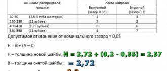
The procedure for adjusting valve thermal clearances is the same for carburetor and injection engines. The only difference is the thermal clearance of the valves. On a carburetor engine, the clearances on all valves are set to 0.15 mm when the engine is cold, and on an injection engine, 0.20 mm. Adjustment begins with setting marks on the crankshaft and camshaft.
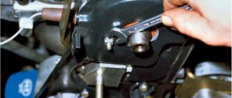
By turning the nut securing the belt drive pulley (drive disc on an injection engine) with a special wrench to “38”, we align the mark in the form of a mark on the pulley with the protrusion on the front cover, while the mark on the camshaft sprocket should coincide.
In this position, the piston of the fourth cylinder is at TDC (00 kV) and the eighth and sixth valves are adjusted (numbering from 1st to 8th starts from the radiator).
For this:
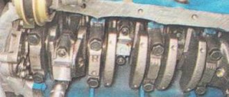
- the dipstick is inserted between the camshaft cam and the working surface of the valve lever;
- use key 17 to loosen the locknut to allow free movement of the adjusting bolt;
- by rotating the adjusting bolt with wrench 13, achieve a gap value at which the feeler gauge will move with little effort;
- holding the wrench 13 against turning the adjusting bolt, tighten the locknut.
It must be borne in mind that when tightening the lock nut, the resulting gap may “move” to a larger or smaller direction, so it is important to re-check the thermal gap after fixing the adjusting bolt.
The next pair of valves is adjusted by turning the crankshaft by 1800, while the camshaft sprocket will rotate by 900. The mark on the sprocket will be located at the cut of the junction of the lower and upper camshaft beds.
In this position the fourth and seventh valves are adjusted.
By positioning the crankshaft 360 degrees, the first and third valves are adjusted. And in the position of the shaft set at 540 degrees, the fifth and second are subject to adjustment.
Examination
After all the valves have been adjusted, use a 38mm wrench to turn the crankshaft 3-4 full turns and take a control measurement of all clearances using a feeler gauge. If there are no gap violations, you can close the cylinder block cover and try to start the car engine.
Fines for crossing the stop line and speeding will no longer bother you!
Checking valve clearance using a feeler gauge
Video: how to adjust valves on a VAZ 2107 injector with your own hands
Adjustment order table:
On a carburetor engine, to more accurately determine the position of the camshaft, it is possible to use a distributor, the slider of which is directed to the socket of the high-voltage wire of the corresponding cylinder. If the distributor cover is removed, then four screws on the housing that coincide with the sockets of the high-voltage wires can serve as a guide.
You can also use the distributor with the cover removed: connect a control light to the low-voltage circuit and turn the crankshaft with the ignition on. The moment the light turns on indicates the exact position of the camshaft at which the corresponding pair of valves is adjusted.
How to determine if the valve is tightly seated on the seat?
If you have removed the head, be sure to pay attention to the valves; at first glance, it may seem that the valves are good, but there is one sure sign that the valve definitely needs to be changed or ground in. Valves can be of different colors, white, brown, black, etc. This is normal, it all depends on the carburetor settings and engine oil consumption. But if the valve has different shades as shown in the photo below, this is a sure sign that the valve is poorly ground to the seat. This valve must be ground in or replaced with a new one, but it must be ground in.
Photo. Valve showing signs of burnout.
The valve in the photo can still be ground in, but if there is a blue tint, it is better to replace such a valve with a new one.
Two-step technique
There is a simplified method for adjusting valves in two steps.
- Set the crankshaft to top dead center.
- We combine the marks on the camshaft and the shaft bed.
- We adjust the 4th, 6th, 7th, and 8th valves.
- Immediately after this, turn the crankshaft a full turn.
- We adjust the 1st, 2nd, 3rd and 5th valves.
The two-turn adjustment technique allows you to reduce the time for servicing the gas distribution mechanism, and is also convenient for beginners to carry out this procedure with their own hands.
On a Chevrolet Niva car and a number of Niva cars, the thermal valve clearances are adjusted automatically by hydraulic compensators.
Replacing valve stem seals with your own hands
One of the reasons why your VAZ 2109 or 2108 may begin to consume oil above normal is the wear of the valve stem seals, or as they are also called, valve seals! You can replace them yourself, but for this you will need not only a set of keys, but also special tools. A complete list of the required tools will be given below:
- valve depressurizer
- cap remover
- spark plug head with knob
- tin rod or coil of rope
- flat blade screwdriver
- long-nose pliers or tweezers
- magnetic handle - preferable
Before we get to the details we need, we will need to perform a number of preparatory work, including:
- Removing the engine valve cover
- Removing the camshaft and its housings
After everyone has done this, the following picture should open before you:
The top photo shows the valve lifters along with the shims. They also need to be taken out, and be sure to be folded in a strictly defined sequence. That is, so as not to confuse them during reinstallation. If this is not done, then the thermal clearances of the valves will be incorrect, and you may not even be able to start the engine.
After this, it is necessary to secure the rail for installing the desiccant and secure it to the outer studs of the camshaft mounting with nuts, as shown in the photo below:
Next, install the lever so that it can be used to recess the valve:
Now we turn the spark plugs out of those cylinders where the valve seals need to be replaced, and insert the rod into the spark plug hole
It is important that it gets between the valve and the piston. To do this, it is necessary to bring the piston of the first cylinder to TDC
Or you can stuff a rope into the hole until it completely fills the combustion chamber. Now you can recess the valve using the lever:
And at this moment, use a magnetic handle to pull out the valve cotters:
Then you can carefully release the lever and proceed to further actions. We take out the plate and two valve springs, and now we take the oil seal remover for the VAZ 2109-2108, and use it to press the cap through the well into the cylinder head. Then you need to tap the weights several times from top to bottom to press the oil seal:
Pressing the weight down, we try to pull out the cap and remove it from the valve:
We take a new oil seal, first dip it in fresh oil and press it back onto the valve. When performing this procedure, you must be extremely careful not to damage both the valve itself and the surface of the head. You should put a special protective cap on top of the valve, which in theory should come complete with seals. You need to press it with the other side of the puller until it stops so that it sits in its place:
We perform a similar procedure with the remaining valves and do not forget to take precautions to avoid damage to the cylinder head. Upon completion of the repair, install all the removed parts in the reverse order.
Adjustment Tools
The adjustment procedure begins with disassembling the valve cover and parts that prevent access to it.
Necessary tools for preparing the gas distribution mechanism for adjustment:
- 1/2 inch ratchet wrench with extension and socket for “10” and “8”;
- universal screwdriver;
- pliers.
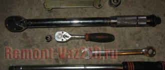
To adjust the thermal clearances of the valves, the following tool is required:
- Ratchet key to “38”;
- Open-end wrench 17;
- Open-end wrench 13;
- The probe is 0.15 mm thick (for an injection engine - 0.20 mm).
Special tools and accessories
1. Rolling hydraulic jack. A standard car jack is often either inconvenient or simply useless when performing some jobs.
2. Stand (support) for the car,
adjustable in height and with a permissible load of at least 1 ton. It is advisable to have four such stands.
3. Wheel chocks
(at least 2 pieces).
4. Double-sided wrenches for brake system fittings 8, 10
and 13 mm.
The two most common types of these wrenches are the clamp wrench and the slotted socket wrench. The clamping wrench allows you to unscrew fittings with worn edges. To put the wrench on the brake pipe fitting, you need to unscrew the pinch bolt. A socket wrench with a slot allows you to do the job more quickly, but such a wrench must be made of high-quality steel with appropriate heat treatment.
5. Special forceps
for removing retaining rings. There are two types of such pliers: sliding - for removing retaining rings from holes and sliding - for removing retaining rings from shafts, axles, and rods. The tongs also come with straight and curved jaws.
6. Oil filter puller.
7. Universal two-jaw puller for removing pulleys, hubs, gears.
8. Universal three-jaw pullers
for removing pulleys, hubs, gears.
9. Universal joint remover.
10. Puller and mandrel for replacing valve stem seals.
11. Desiccant for disassembling the valve mechanism of the cylinder head.
12. Tool for removing ball joints.
13. Device for removing the piston pin.
14. Device for pressing out and pressing in silent blocks of front suspension arms.
15. Tool for removing steering rods.
16. Crankshaft ratchet key.
17. Spring remover.
18. Impact screwdriver with a set of attachments.
19. Digital multimeter for checking the parameters of electrical circuits.
20. Special probe or 12 V test lamp
to check electrical circuits of the vehicle that are under voltage.
21. Pressure gauge
to check tire pressure (if there is no pressure gauge on the tire pump).
22. A device for adjusting clearances in valve actuators.
23. Compression gauge for checking the pressure in the engine cylinders.
24. Bore gauge for measuring the diameter of cylinders.
25. Vernier caliper with depth gauge.
26. Micrometers with a measurement limit of 25-50 mm and 50-75 mm.
27. Set of round probes
to check the gap between the spark plug electrodes. You can use a combination key to service the ignition system with a set of necessary probes. The key has special slots for bending the side electrode of the spark plug.
28. Set of flat styli
for measuring gaps when assessing the technical condition of units.
29. Wide probe 0.15 mm
to check valve clearances.
30. Mandrel
for centering the clutch driven disc.
31. A mandrel for crimping piston rings when installing the piston into the cylinder.
32. A hydrometer for measuring the density of a liquid (electrolyte in a battery or antifreeze in an expansion tank).
33. Special device with metal brushes
for cleaning battery wire terminals and terminals.
34. Oil syringe
for filling oil into the gearbox and rear axle.
35. Pressure syringe
for lubricating the driveshaft splines.
36. Hose with bulb for pumping fuel.
The hose can be used to remove fuel from the tank before removing it.
37. Medical syringe or bulb
for sampling fluids (for example, if it is necessary to remove the master cylinder reservoir without draining all the brake fluid from the system). The syringe is also indispensable for cleaning carburetor parts.
When performing the work, you may also need: a technical hair dryer (heat gun), an electric drill with a set of metal drills, a clamp, tweezers, an awl, a tape measure, a wide bench ruler, a household steelyard, wide containers for draining oil and coolant with a volume of at least 10 liters.
Adjustment with a micrometer
The most accurate method for regulating valve thermal clearances is to use a device with a dial indicator - a micrometer. A micrometer is a very sensitive device that responds to changes in the translational movement of its measuring rod every hundredth of a millimeter.
The procedure is similar to the order of adjustment using a feeler gauge. The peculiarity of this method is to install a rail on the studs of the camshaft bed, onto which a micrometer is attached. The rack contains information on the angles of the crankshaft position to the valves corresponding to adjustment.
Before starting work, the micrometer is mounted on a device that has a lever in the form of a rocker arm. One side of the lever rests on the micrometer rod with a light touch, and the other on the extreme part of the rocker. By lifting the rocker without force with a special “spade” until it touches the back side of the camshaft cam, note how many divisions the arrow has deviated from the zero position. For a carburetor engine, the needle should deviate by 52 divisions.
A micrometer for adjusting valves is supplied with a description and all necessary accessories.
A homemade rail can be made according to a factory design. With the help of such a rack, the actions when independently adjusting the valves are more confident and there is no need to remember the routine or sequence of operations.
Why do you need a guide bushing?
The guide bushing can quite rightly be considered the main element on which the resource and proper operation of the “seat - valve plate” tandem depends. The material from which the part is made and its design itself are primarily aimed at working under conditions of high speeds of the valve stem fixed in it, constant high-temperature loads and the almost complete absence of lubrication in the valve-bushing pair.
Causes and consequences of deformation
The described conditions lead to the fact that during engine operation, the valve guide bushing also wears out, which is why, over time, its alignment with the valve stem may be disrupted. Subsequently, the part breaks even more and the valve begins to “walk” and does not fit tightly to its seat, and this, in turn, leads to the chamfer of the seat breaking over time. As a consequence, you can get a burnout of the valve and have to replace the seat.
Appearance of bronze guide bushings for VAZ 2108–2109 models
Also, due to the “walking” of the valve in a broken guide, the oil seals can quickly become unusable. They simply will not be able to hold oil with increased angular displacement of the valve stem. The result will be oil getting into the engine, and if you also take into account that more oil will pass through the broken bushing than usual, then the situation will not be pleasant. Carbon deposits on valves and other parts around the combustion chamber will increase, the level of harmful exhaust emissions will increase, and you may end up with a prematurely failed catalytic converter. And simply replacing the valve stem seals is not enough, as the problem will soon return again.
Why you shouldn't neglect checking
When repairing an engine, it is better to pay special attention to its head. Often it is this part of the engine that is to blame for the fact that the level of compression in the cylinders is far from the desired
When repairing cylinder heads, motorists sometimes limit themselves to only grinding the valves to their seats, believing that there is nothing particularly wearable in all-metal bushings. At the same time, checking how large the gap between the part and its valve is will be completely worthwhile. When the obtained clearance figures go beyond those recommended by the car manufacturer, then no amount of grinding in the valves or replacing the valve stem seals will protect against problems in the future.
Materials used to make bushings
For the manufacture of bushings, materials with good wear resistance and thermal conductivity are used. Among these you can find:
- special cast iron alloys;
- bronze;
- brass;
- metal ceramics.
In terms of thermal conductivity and cost, brass, along with bronze, are among the leaders, so the vast majority of bushings are made from alloys of these metals.
Nuances to consider
Most bushings have a special support collar on the outside, designed to ensure proper fixation of the part vertically in the cylinder head. If the part is smooth, then installation is carried out using a special mandrel.
For intake valves, the guide bushings should not protrude so as not to increase the aerodynamic drag of the intake channel. Exhaust valve bushings are designed to “hide” the valve stem as much as possible to protect the latter from high temperatures and better heat dissipation.
Appearance and location of the valve guide in the cylinder head
We recommend: How to properly bleed the brakes on a VAZ-2114?
The manufacturing precision of the bushings is very high. This is necessary to obtain the most accurate alignment and the best fit of the valve plate and seat during engine operation. The outside of the body of the part that is to be pressed into the cylinder head must be processed as cleanly as possible; there should be no scratches or marks on it. This ensures optimal heat removal from this accessory to the block head.
Consequences of untimely adjustment
Untimely maintenance of the gas distribution mechanism negatively affects engine performance, causing unbalanced operation. The engine runs rough, there is no traction performance, and fuel consumption increases. It is known that the injection phase is directly dependent on the thermal clearance of the valves. Correct and correct adjustment allows the valves to open and close in a timely manner. If the gap is set less than the permissible value, then the valve begins its operation with some advance, and vice versa, if the gap is large, it opens late. Reduced clearance on exhaust (hot) valves increases the time they remain open, which can cause the edges to slowly burn out, leading to loss of compression in the cylinder.
When operating the engine on gas (propane or methane), the thermal clearances must be adjusted with the same gaps, the value of which is determined by the instructions for operating the engine on gasoline. Adjusting the valves for gas does not have scientific and technical validity and can lead to unstable engine operation.
Signs of poor valve clearance
Before describing the adjustment process, you should understand the signs of incorrect clearance, as well as what this leads to. So, the main sign of a broken timing gap is a metallic knock at the top of the engine. Usually this knocking sound initially appears only in a certain operating mode, but over time it will be heard in all modes.
Related link:
Description and installation of the “Lunfey” heater on a VAZ
Of course, the gap can either decrease from the nominal value or become larger. Both decreasing and increasing the gap will primarily lead to a loss of power. With a smaller gap, the lever will tighten the valve, which will significantly reduce the tightness in the cylinder and ensure a drop in compression. As a result, this can lead to burning of the valve edge and its seat.
An increased gap will affect the filling of the cylinder combustion chamber, since its opening time will be reduced, and exhaust gas removal will also be incomplete. To avoid the above problems, it is necessary that the VAZ-2105 valves be adjusted after approximately 15-20 thousand km , as well as at the first appearance of a violation of the thermal clearance.
How to adjust valves on a VAZ 2101-2107?
1) First, remove the cylinder head cover. (For information on how to remove the cylinder head cover, read the article, “Setting the valve timing by marks,” in the “ removal ” section, from point 1-10)
2) Then set the piston of the fourth cylinder to the TDC position. (For information on how to install the piston of the fourth cylinder to the TDC position, see the article “Installing the piston of the fourth cylinder to the TDC position”)
3) Then adjust the “eighth and sixth” valves, but before you start adjusting them, check if they need adjustment, to do this:
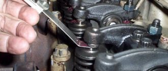
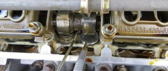
1. Insert the feeler gauge into the valve gap and see how it moves there.
Note! When you insert the feeler gauge into the gap, it should move there with little difficulty, but if it moves smoothly in and out of the gap, then the valve needs adjustment!
4) If the valves need adjustment, then:
1. Insert the probe into the “sixth or eighth” valve and then use the key indicated under the letter “B” to loosen the lock nut.
2. At the same time, use another wrench to set the valve gap you need by unscrewing or tightening the adjusting bolt, which is marked with the letter “A”.
3. And to complete the operation, tighten the bolt indicated under the letter “B”.
5) Next, read the section “Sequence of valve adjustment” just below, and adjust all the remaining valves on your car.
In what order should the valves be adjusted?
Note! Before you start studying, remember one thing that will be indicated in the instructions, namely, it will say that the crankshaft will need to be turned “180°”, which means half a turn! (The crankshaft revolutions are easy to understand by following the mark on the camshaft)
1) You should start adjusting the valves:
1. First from the “sixth and eighth” valves.
2. Then you will need to turn the crankshaft clockwise, exactly 180° and then begin adjusting the “fourth and seventh” valves.
3. Next, again turn the crankshaft 180° clockwise, and this time adjust the “first and third” valves.
4. And to complete the work, turn the crankshaft 180° clockwise again, and then adjust the “second and fifth” valve.
Important! 1) Do not disturb the order of valve adjustment! 2) The valves need to be adjusted only on a cold engine!
For newbies! Question: What does the gap adjustment feeler look like? Note: The photo shows two types of probes!
Additional video clip: Especially for you, we have prepared an interesting video clip, after watching it, most of your questions about valve adjustment will most likely disappear, but if you still have questions, then ask them in the comments and we will answer them for you.
How to adjust valves on a VAZ 2101-2107?
1) First, remove the cylinder head cover. (For information on how to remove the cylinder head cover, read the article, “Setting the valve timing by marks,” in the “ removal ” section, from point 1-10)
2) Then set the piston of the fourth cylinder to the TDC position. (For information on how to install the piston of the fourth cylinder to the TDC position, see the article “Installing the piston of the fourth cylinder to the TDC position”)
3) Then adjust the “eighth and sixth” valves, but before you start adjusting them, check if they need adjustment, to do this:
1. Insert the feeler gauge into the valve gap and see how it moves there.
Note! When you insert the feeler gauge into the gap, it should move there with little difficulty, but if it moves smoothly in and out of the gap, then the valve needs adjustment!
4) If the valves need adjustment, then:
1. Insert the probe into the “sixth or eighth” valve and then use the key indicated under the letter “B” to loosen the lock nut.
2. At the same time, use another wrench to set the valve gap you need by unscrewing or tightening the adjusting bolt, which is marked with the letter “A”.
3. And to complete the operation, tighten the bolt indicated under the letter “B”.
5) Next, read the section “Sequence of valve adjustment” just below, and adjust all the remaining valves on your car.
In what order should the valves be adjusted?
Note! Before you start studying, remember one thing that will be indicated in the instructions, namely, it will say that the crankshaft will need to be turned “180°”, which means half a turn! (The crankshaft revolutions are easy to understand by following the mark on the camshaft)
1) You should start adjusting the valves:
1. First from the “sixth and eighth” valves.
2. Then you will need to turn the crankshaft clockwise, exactly 180° and then begin adjusting the “fourth and seventh” valves.
3. Next, again turn the crankshaft 180° clockwise, and this time adjust the “first and third” valves.
4. And to complete the work, turn the crankshaft 180° clockwise again, and then adjust the “second and fifth” valve.
Important! 1) Do not disturb the order of valve adjustment! 2) The valves need to be adjusted only on a cold engine!
For newbies! Question: What does the gap adjustment feeler look like? Note: The photo shows two types of probes!
Additional video clip: Especially for you, we have prepared an interesting video clip, after watching it, most of your questions about valve adjustment will most likely disappear, but if you still have questions, then ask them in the comments and we will answer them for you.
The result of the work done
As a result of correct adjustment of the valve mechanism, engine operation stabilizes, power and traction appear again. A correctly configured gas distribution mechanism stabilizes fuel consumption, because if configured incorrectly, it increases.
If there is no excessive wear in the timing mechanism parts, then, as a rule, excessive noise in the valve cover area disappears. To keep the engine in full working order and its performance within normal limits, this operation must be performed every 10,000-15,000 km.
Source