As you remember, last time we looked at how to replace the timing chain and sprockets with new ones. However, before installing the valve cover in place, it is necessary to adjust the thermal clearance in the valve drive. Today we will analyze this moment.
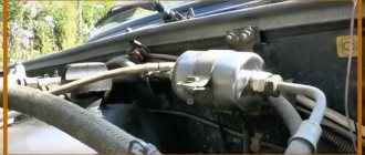
The gap is adjusted after work involving intervention in the gas distribution mechanism, when a loud knocking occurs on a warm engine, and also every 10 thousand kilometers (according to the operating manual). Before work, you need to check and adjust the chain tension, which we did earlier. The adjustment is carried out with a flat, wide feeler gauge 0.15 mm thick or an adjusting rod at an engine temperature of 20 C°, however, it can also be done at a different temperature by making the necessary adjustment.
| The release can be ignored |
However, it should be borne in mind that then you will need a set of probes of various thicknesses.
Rack adjustment is considered the most accurate for setting the clearance, even with significant wear on the camshaft and valve levers (rockers). Using a feeler gauge to set the correct gap on parts even with low production is already problematic, but this option is simpler and more accessible in garage conditions. So, we will need:
- socket wrenches “8”, “10”
- wrenches “13”, “17”
- flat screwdriver
- special wrench or socket for the crankshaft nut (ratchet)
- probe 0.15 mm
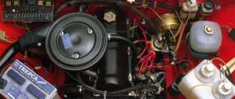
Before starting work, you must turn off the engine and allow it to cool to the required temperature. Remove the cylinder head cover, having first removed or moved aside the interfering pipes and filters.
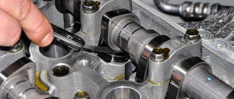
Now you need to install the crankshaft and camshaft to the position of the top dead center of the 4th cylinder (TDC), aligning the factory marks on the crankshaft pulley and camshaft sprocket with the corresponding ebb marks on the engine body.
This can be done using a special wrench (or socket), turning the crankshaft by the nut clockwise.
Or by jacking up the rear wheel and spinning it in 4th gear, we ensure that the marks match.
To make work easier, you can unscrew the spark plugs and remove the alternator belt. So, in this position we can adjust the thermal clearance on the 8 and 6 valves. Sequential numbering starts from the camshaft sprocket.
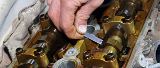
To do this, insert the dipstick into the gap between the rocker and the camshaft cam. If it fits quite freely without noticeable resistance or, conversely, when it “bites”, it is necessary to make an adjustment: use a “17” wrench to loosen the lock nut of the adjusting bolt and use a “13” wrench to tighten or unscrew the bolt, having achieved the required clearance, tighten the lock nut back.
When tightening the locknut, you must keep in mind that the gap will decrease slightly, so an adjustment should be made. It is unlikely that you will be able to select the gap the first time - as a rule, this comes with skill.
After adjustment, the probe should enter with noticeable force, bend a little, but not “bite”. Consistently turning the crankshaft 180° (camshaft 90°), we check and adjust the clearances of the next pair, observing the order.
To make adjustment work easier, additional marks can be applied to the crankshaft pulley and camshaft sprocket.
After the adjustment is completed, the crankshaft should make almost two revolutions, and the camshaft should make almost one revolution. We check again the tightness of all locknuts. To be on the safe side, you can crank the crankshaft and check the clearances again.
Reinstall the removed parts in reverse order.
Subscribe to the blog! Good luck on the roads!
Source: https://autovazremont.blogspot.com/2018/02/regulirovka-zazora-klapanov-vaz-2107.html
Lightweight VAZ valves, specifics
The most important thing in modified valves is the donor. In Russian: we won’t make candy out of shit. Once I fell for the “client’s cry” and tried to make a modified version from the “Chelyabinsk donor”. The only advantage of Chelyabinsk residents is heat-resistant steel. The rest...turn off the lights and drain the water. Initial measurements showed that the axial runout of the chamfer on some valves reached 2-3 hundredths, which means that the valves can then be ground in until they turn blue. I also had to modify the chamfer. When all the costs were added together, the price exceeded the final product if the donor had been a high-quality German or Polish valve. Our “tuners” usually take Samara valves as a basis. Of course, the main argument is: well, this is a pipeline supplier. I will not argue. I am still ready to consider them as a “standard spare part”, but never as a donor.
Signs and consequences of improper clearance
After starting the engine, it itself and all its parts begin to heat up significantly and automatically expand
It is also worth taking into account the natural wear and tear of the elements in contact with each other. All this is the basis for ensuring strictly established gaps between certain parts
If the gap is larger than the required size, the driver will begin to hear the characteristic clatter of the engine, which gradually goes away as the car warms up. With increased clearance, the camshaft fist does not push through the rocker of the valve stem, but simply begins to knock on it.
Such long-term shock load leads to such unpleasant consequences as:
- significant reduction in valve life;
- riveting;
- chipping of the end, which further increases the gap;
- increased noise during engine operation.
With a very small gap, the car engine will not be able to fully realize its functionality. This will automatically affect the overall speed and dynamic characteristics of the vehicle. At the same time, there will be significant overheating of all exhaust valves with melting of their edges. Among the main consequences of a reduced gap size are the following factors, based on the loss of combustion chamber tightness:
- Reducing compression due to the release of the air-fuel mixture.
- During the working stroke, exhaust and hot gases break through and lead to severe burnout of the valves.
- The plates no longer touch the seats, which disrupts heat transfer.
- The valves are heated to temperatures that significantly increase corrosion and oxidation.
- Increased load on timing belts.
Based on everything said above, we can conclude that adjusting the gaps must be done without fail. The process must be carried out if the following signs are present:
- in the upper part of the cylinder head of installed cylinders there is an extraneous, slightly ringing noise;
- repair of the gas distribution mechanism;
- the adjustment was made more than 20 thousand kilometers ago;
- a clear decrease in engine output;
- increased fuel consumption.
It is advisable to combine the adjustment with an oil change. This will prevent dirt, sand and dust from getting into the engine.
Do-it-yourself adjustment of VAZ 2101 valves
Valve adjustment is a very important procedure, on which a lot depends, for example: stable engine operation, fuel consumption, power and normal engine starting. Not all motorists know how to adjust valves; the vast majority entrust this work to service station specialists, others turn to friends and acquaintances for help, and there are those who know the adjustment procedure and do it themselves.
Today I will talk about how to adjust the valves on a VAZ 2101 with your own hands.
Before you begin adjusting the VAZ 2101 valves, you need to acquire all the necessary tools, so as not to be distracted later, for this work you will need the following set:
- Flat feeler gauge A.95111, its thickness is 0.15 mm or a special device for adjusting the gap between the camshaft cams and levers.
- Spare valve cover gasket (you never know what might happen, you'll break it by accident.)
- Screwdriver Set.
- Set of socket and open-end wrenches.
Features of the VAZ-2107
Now about the procedure for adjusting valves on a VAZ-2107 (carburetor). As for the work, they are identical to what was described - we disassemble, check, adjust if necessary and reassemble.
But here it is possible to use a somewhat simplified valve adjustment scheme for the VAZ-2107.
It boils down to the fact that after installing the TDC of the 4th cylinder, not two valves are checked and adjusted, but four - the 8th, 7th, 4th and 6th. That is, both valves of the 4th cylinder are regulated, as well as the exhaust valve of the 2nd and the intake valve of the 3rd cylinder.
Then rotate the crankshaft 360 degrees. (180 degrees of rotation of the distributor slider) and check and adjust the remaining 4 valves - 3rd, 5th, 2nd and 1st.
As for the injection version, the difference in everything comes down to only a slight difference in the marks on the crankshaft.
This is how you can independently set the thermal gap on classic VAZ cars.
Why are guide bushings needed?
At the beginning and middle of the last century, car cylinder heads were made of cast iron, and the valves were simply inserted into precisely drilled holes. But subsequently, manufacturers abandoned cast iron heads due to their heavy weight and insufficient removal of excess heat, and they were replaced by lightweight cylinder heads made of aluminum alloys. These metals have excellent thermal conductivity, but have little resistance to wear from friction.
To solve the problem, a guide sleeve was invented - an intermediary between the soft alloy of the cylinder head and the steel valve stem, which constantly moves up and down during operation. Made of cast iron or special bronze, it is securely pressed into the cylinder head body, and the valve is inserted inside with minimal clearance.
The engine diagram shows the location of the guide bushings
The bushing itself is a hollow cylinder, made exactly to size for a specific car model. The outer surface is polished and smooth to the touch, and the inner surface has a spiral-shaped groove in the form of a thread. Motor oil moves along it, lubricating the valve axis and reducing friction. A shallow recess is made in the upper part of the guide part, into which a retaining ring is inserted.
On the left is the bushing for the exhaust valve, on the right is for the intake valve
Bronze bushings for VAZ 2109 all look the same
Bushings perform the following functions:
- as the name implies, they direct the movement of the valve so that its plate is clearly aligned with the seat and fits tightly to it;
- take on the load from the friction force that occurs during the translational and reciprocal movement of the valve stem;
- the valve cup gets very hot in the combustion chamber, and the bushing transfers this heat to the aluminum alloy of the cylinder head;
- Thanks to a special groove, the part provides lubrication of rubbing surfaces.
Cast iron parts of VAZ 2106 - intake bushings are shorter than exhaust bushings
When the element is pressed into the cylinder head hole, its upper part of smaller diameter protrudes several millimeters above the surface. This is necessary to install an oil seal on it (also known as a valve seal), which prevents lubricant from the upper part of the engine from entering the combustion chamber through the inner hole of the bushing.
This is what the protruding part looks like where the oil seal is put on
Countersinks and cutters for repairing valve seats – what to choose?
Replacing valve seats with your own hands requires the presence of not only a rough tool, but also an almost jewelry one - a roller cutter or a countersink. These highly specialized tools are used only for repairing internal combustion engines. A set of cutters for valve seats is used to grind out the desired shape of their internal diameter. This operation allows you to achieve a tight seal from the plate. In order to accurately process the valve seat, it is advisable to have a drawing of the mechanism at hand.
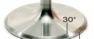
The cutter is made in the form of a metal cylinder, in which there is a hole and two or one conical surface; its angle can vary from 15 to 60 degrees. There are incisors on the surface of the cone. A set of countersinks for repairing valve seats is used in the same way as cutters, but there is one difference. The countersink can be used on mechanical and electrical tools.
How to adjust valves
All procedures must be carried out only on a cold engine. This is done to ensure that the setup results remain standard: this is exactly what they do at the manufacturing plants. It is worth noting that the procedure for adjusting the valves on each car is different: you can find it out from the instructions for the car or the relevant literature. The process is carried out by screwing in or unscrewing special adjusting screws, or by selecting flat washers. Each of these options is considered separately.
Using special tools
Engine valves are adjusted using a set of feeler gauges or a special rack and indicator. Both methods are quite widespread: the first is simple, accessible and requires minimal financial and time costs. To apply the second method, you will have to buy a device and a special device.
Adjustment using feeler gauge and locknuts
This method of setting the timing belt is typical for Russian rear-wheel drive cars (“classics”). Algorithm of actions:
- Remove the air filter housing and disconnect all tubes, cables and levers from the valve cover. To make it easier to turn the engine crankshaft, remove the spark plugs.
- Remove the valve cover and the front timing belt cover (if there is one, it may also be a chain).
- Set the piston of the cylinder from which the procedure will begin (for example, in the Zhiguli “classic” it is the 4th) to the top dead center position: the valves will be in the closed position.
- Observing the indentation mark on the engine shaft pulley, rotate it until it coincides with the mark on the lower front cover of the BC. The recessed point on the timing shaft sprocket should also coincide with the mark on its “bed” (housing).
- Use an open-end wrench to hold the adjusting hardware and at the same time loosen the locknut. Next, you need to use a set of feeler gauges to adjust the valves. Select the thin plate you need and insert it between the rocker arm and the valve stem. When adjusted normally, the feeler gauge will pass through with little friction. The gap value must be adjusted according to the table, which is different for each car (for VAZ2101-07 - 0.15 mm). Now tighten the locknut and check the clearance again. Repeat the operation if necessary. Follow the order of valve adjustment: for example, for a VAZ classic: 8-6, 4-7, 1-3, 5-2.
Adjustment using washers
This type of timing adjustment is more typical for front-wheel drive cars. To produce it, you need:
- Remove the valve cover.
- Find the marks on the engine block, timing belt pulley and, turning the crankshaft clockwise, make sure they match. As a result, the first piston will be in the TDC position.
- Determine the gap between the shim and the camshaft cam (they are the first when viewed from the pulley side).
- If there is a larger or smaller gap, select another washer (each has a corresponding marking; if not, use a caliper, or better yet, a micrometer).
- After installing the washer, check the gap again: the permissible deviation is no more than 0.05 mm in both directions.
- Do not forget that the gap size for the intake and exhaust valves is different - this parameter must be found out from the operating instructions for a particular car.
Adjustment using indicator and rack
This method is considered more accurate and was especially popular during the USSR. This adjustment method is good for engines that have been in operation for a long time, since the device and measuring rod take into account the wear on the surfaces of the parts. Progress of the procedure:
- Remove the valve cover, having first disconnected the levers and cables from it.
- Rotate the engine shaft until the marks match, just as when adjusting the valves using a feeler gauge.
- Take the rack and fix it on the cylinder head (fastening is carried out to the studs of the camshaft housing). There is a small nuance: you do not need to completely screw in all 3 nuts securing the rack, otherwise it will dangle. First of all, tighten the outer hardware, then begin to unscrew the middle bolt until the rail becomes motionless.
- Take the dial indicator and secure it to the rail, and place the device’s foot on the edge of the valve cam.
- Using the included grip, grab the cam and pull it up: the indicator needle should pass 52 divisions (at an air temperature of +20 degrees). If this is not the case, then you need to adjust the valve using one of the two methods described above.
If everything you need is available, you can start
- Before starting work, let the engine cool down; its temperature should not be higher than 20°.
- Remove the air cleaner cover and take out the air filter.
- Unscrew the 4 nuts with a key “8”, then you need to remove the hoses going to it (large from below, small from the carburetor side)
- Remove the air cleaner housing.
- Disconnect the choke cable; a screwdriver and a key set to “8” will help you with this.
- Turn off the throttle, remove the spring and washer.
- Using a “10” socket wrench, unscrew the 8 nuts that secure the valve cover.
- Now you can remove the cover.
- Take a prepared 0.15 probe or a special device, if you have one, and open-end wrenches for “17” and “13”.
- Turn the engine until the marks on the crankshaft (front engine cover and pulley), as well as on the camshaft sprocket, coincide.
- In this position, you need to check the gap in cams 6 and 8 (refer to the table below)
- Count the cams from the camshaft sprocket.
- Install the dipstick above the rocker under the camshaft, when viewed from the right side - the location of the dipstick installation is clearly visible. If the dipstick is installed freely, loosen the nut at “17” at the corresponding rocker, holding the nut at “13” from turning with the other hand.
- Next, turn the nut at “13” a little and lock it with the nut at “17”, then check the gap again using a feeler gauge. Your task is to achieve a tight movement of the probe with slight nudging.
- If you managed to achieve the required gap, make the final tightening with the key set to “17”. After this, you can begin adjusting the next cam.
- Rotate the motor shaft clockwise 180°, with the mark on the sprocket pointing to “9 o’clock” when viewed from the camshaft). Here, great accuracy is not particularly important, so everything is approximate.
- The next two cams 4 and 7 must be adjusted according to the table above.
- Next, rotate the motor shaft 180°, the mark on the sprocket is at the bottom (at “6 o’clock”), and on the pulley. must match.
- Adjust cams 1 and 3 according to the table.
- And finally, another 180° turn at the 3 o’clock star. Cams 2 and 5. As a rule, after removing and installing the camshaft, there is a need to turn the starter, then check the clearances again and, if necessary, make adjustments.
- Before closing the cover, make sure that all the nuts on “17” are well tightened; if the gasket is damaged or you damaged it during removal, replace it.
The cover nuts are tightened from the center to the edges (the same as when replacing the camshaft or cylinder head) and the main thing is not to pull too hard. Fortunately, the valve cover is not capricious and, in principle, no tightening rules need to be followed.
Reassemble everything in reverse order and perform a test run. That's all for me, now you know how to adjust the valves on a VAZ 2101, I hope everything works out for you. As you can see, adjusting the valves can be done at home without much difficulty and for this it is not at all necessary to go to a service station and pay a lot of money, you just need to have free time and “direct hands”.
Springs
Basic data for checking the outer valve spring
Lever spring check diagram
A – free size; B – dimension under load
1. Make sure there are no cracks on the springs and whether the elasticity of the springs has decreased, for which check the deformation of the springs under load (Fig. Basic data for checking the outer valve spring, Fig. Basic data for checking the internal valve spring, Fig. Diagram for checking the lever spring ).
2. For lever springs (see Fig. Lever spring check diagram) size A (spring in a free state) should be 35 mm, and size B under load 51–73.5 N (5.2–7.5 kgf) - 43 mm.
Stuffing the valve seals
But first you need to remove the old valve seals, on Zhiguli they must be removed carefully and in no case should you try to knock them off with a blow, the place where the seal is packed will break off, take pliers, hold the valve seal with them and try to turn it if it doesn’t work right away, grab it and try to turn it again, then grab it with the pliers and the valve seal will loosen and rotate and come out. Also remove the valve seals from the UAZ and GAZ.
And now we will fill the valve seals on the Zhiguli, insert the valve and put the valve seal on it up to the guide sleeve, take a tube with an internal diameter of 13 mm and carefully, with a light hammer, tap the valve seal with light blows, just do not overdo it, otherwise you will break the seal. If there is no such tube, you can flatten the larger tube a little to size, and saw the smaller one a little lengthwise and spread it to size. You can also first remove the spring from the valve seal so as not to accidentally damage it and then put it on the seal.
On UAZ and Gas, fill it in the same way as on Zhiguli, but the tube should have an internal diameter of 16mm.
How to adjust valves on a VAZ 2110
There is no need to purchase shims in advance. They are relatively expensive. Initially, you have to establish the size of the gaps and only then buy the required number of washers with the exact dimensions. It is better to carry out work in a garage with good lighting. The roof and walls will protect from unwanted wind and rain, which can carry dirt into the open camshaft.
Disassembly
If everything is ready, then we proceed to the first part of the repair - dismantling the parts:
- disconnect the terminal from the battery;
- remove the air filter housing (on a carburetor engine);
- disconnect the crankcase gas hoses and the throttle cable bracket from the valve cover;
- unscrew the bolts of the timing case. Remove the cover and gain access to the pulley;
- unscrew the spark plugs (this will make it easier to rotate the crankshaft to find TDC and BDC);
- Unscrew the valve cover nuts and remove it.
Before direct tuning, you should remember the mechanism of operation of the timing belt. Namely, the operating order of the valves (in our case, a VAZ 2110 with an 8-valve injector).
| Camshaft rotation angle, degrees | Cam No. (counting from camshaft pulley) | |
| Exhaust (gap 0.35.mm) | Inlet (gap 0.20mm) | |
| 0 plus 2-3 teeth | 1 | 3 |
| 90 plus 2-3 teeth | 5 | 2 |
| 180 plus 2-3 teeth | 8 | 6 |
| 270 plus 2-3 teeth | 4 | 7 |
| Crankshaft rotation angle, degrees | N of the cylinder in which the compression stroke occurs (end) | N adjustable valves (cams) |
| 4 | 8 and 6 | |
| 180 | 2 | 4 and 7 |
| 360 | 1 | 1 and 3 |
| 540 | 3 | 5 and 2 |
The procedure for adjusting the valves on a VAZ 2110 with an 8-valve engine must be performed in the same sequence as in the table. As for installing valves on a VAZ 2110 with 16-valve engines, the diagram looks completely different.
| valve | 1 class (you) | 2 cells (ch) | Zkl (vp) | 4th grade (you) | 5th grade (you) | 6 cells (ch) | 7 cells (vp) | 8th grade (you) |
| Should ±0.05 | 0,30 (0,35) | 0,20 | 0,20 | 0,30 (0,35) | 0,30 (0,35) | 0,20 | 0,20 | 0,30 (0,35) |
| largest gap | 0,25 | 0,35 | 0,40 | 0,35 | 0,40 | 0,30 | 0,30 | 0,40 |
| washer | 4,30 | 3,82 | 3,52 | 4,22 | 4,50 | 4,27 | 3,87 | 4,25 |
| What kind of washer is needed | 4,25 (4,20) | 3,97 | 3,72 | 4,27 (4,22) | 4,6 (4,55) | 4,37 | 3,97 | 4,35 (4,3) |
Adjustment
After removing the valve cover, it is necessary to remove any remaining engine oil near the tappets. This can be done with a medical syringe or a rubber bulb. If there is a retaining rod, you should install it on the two outer studs intended for fastening the cylinder head cover.
Then, we proceed to the second part of the repair and do the following:
- We set the top dead center by aligning the marks of the camshaft pulley and the inner timing case. There are two ways to do this. Hanging and rotating one front wheel. Use a spanner wrench (head) to rotate the camshaft by the pulley mounting bolt, but this operation is dangerous due to breakage of the mounting bolt;
- After finding the top dead center, turn the camshaft slightly so that the pulley moves 40-50° from TDC (this is 2.5-3 teeth). We put our mark, from which we will then rotate the camshaft several more times, making additional marks;
- We measure the thermal clearance of the first valve (exhaust) by slipping one of the feeler gauges (0.35/0.4/0.45 mm) between the camshaft cam and the pusher. Nominal clearance 0.35 mm;
- if the first probe passes freely, then take a larger size (0.4 mm). The pitch is 0.05 mm;
- if the 0.4 or 0.45 probe does not pass, then it is necessary to replace the adjusting washer;
- We turn the pusher with the groove towards us, press it with the lever of the locking rack and take out the used washer with tweezers. Its inner side contains numbers with the original size;
- to calculate the required value, you must use the formula H = B + (A - C). Where:
- H—thickness of the new washer, mm;
- B—thickness of the used washer, mm;
- A - measured gap, mm;
- C—nominal gap, mm.
- The resulting result H is written down in a notepad. You will have to buy a washer of this exact size for the repair valve, rounding up the value;
- according to the table, we move on to the third valve (intake), its nominal clearance is 0.2 mm;
- measure the gap by inserting feeler gauges in order: 0.2/0.25/0.30 mm;
- write down the size of the probe, which is not included in the thermal gap;
- take out the washer and calculate the repair size using the above formula;
- then, according to the table, we turn the crankshaft several times to the indicated degrees and perform the operation with all the valves;
- We go to the store and buy the required number of adjusting washers of the required thickness, according to calculations;
- We install the washers in the pushers, according to the notebook;
- all valve clearances on the VAZ 2110 should be restored to the nominal sizes of 0.2 and 0.35, thanks to the use of adjusting washers;
- checking new thermal gaps;
- after replacing the washers, it is necessary to put the dismantled parts in place;
- we start the engine and observe its operation.
Operating principles of engine valves
The camshaft and crankshaft of the engine are connected to each other via a gear, belt or chain drive, with an optimal ratio of 2:1. For one revolution of the distribution element, the crankshaft makes two revolutions. The shape of the camshaft cams is able to ensure that the valves close and open so that they correspond to the position of the crankshaft, the engine stroke, and the distribution phases.
During engine operation, all parts increase slightly in size due to slight heating. As a result, the overall distance between the camshaft and the valve lifter changes. When the engine warms up to optimal operating temperature, the pushrod is pressed tightly against the valve and camshaft. This ensures the most efficient operation of the engine.
If the end of a closed valve is fixed in a position above the pushrod, a gap is formed between the seat and the plate, reducing engine compression. If the end of a fully closed valve is located below the pushrod, during the corresponding valve timing phase it will open slightly less than necessary. As a result, the engine power will be reduced, since the less the valve is open, the worse air and exhaust gases will escape through it.
Springs
Basic data for checking the outer valve spring
Lever spring check diagram
A – free size; B – dimension under load
1. Make sure there are no cracks on the springs and whether the elasticity of the springs has decreased, for which check the deformation of the springs under load (Fig. Basic data for checking the outer valve spring, Fig. Basic data for checking the internal valve spring, Fig. Diagram for checking the lever spring ).
2. For lever springs (see Fig. Lever spring check diagram) size A (spring in a free state) should be 35 mm, and size B under load 51–73.5 N (5.2–7.5 kgf) - 43 mm.
Checking the quality of work
After completing the repair, it is necessary to check the operation of the engine. First, we install all the dismantled elements in place and screw in the spark plugs. After starting the engine, there should be no knocking of valves or other extraneous noise. We recommend carrying out checks for 15-20 minutes - this will ensure that the cylinders are operating normally even after heating.
It is not difficult to adjust the valves on the VAZ-2109 model yourself. You can do this work yourself, the main thing is to have a special kit and a couple of hours of free time. Using step-by-step instructions and an adjustment diagram, you will do the job efficiently and save on a trip to the car service center.
Why do you need a guide bushing?
The guide bushing can quite rightly be considered the main element on which the resource and proper operation of the “seat - valve plate” tandem depends. The material from which the part is made and its design itself are primarily aimed at working under conditions of high speeds of the valve stem fixed in it, constant high-temperature loads and the almost complete absence of lubrication in the valve-bushing pair.
Causes and consequences of deformation
The described conditions lead to the fact that during engine operation, the valve guide bushing also wears out, which is why, over time, its alignment with the valve stem may be disrupted. Subsequently, the part breaks even more and the valve begins to “walk” and does not fit tightly to its seat, and this, in turn, leads to the chamfer of the seat breaking over time. As a consequence, you can get a burnout of the valve and have to replace the seat.
Appearance of bronze guide bushings for VAZ 2108–2109 models
Also, due to the “walking” of the valve in a broken guide, the oil seals can quickly become unusable. They simply will not be able to hold oil with increased angular displacement of the valve stem. The result will be oil getting into the engine, and if you also take into account that more oil will pass through the broken bushing than usual, then the situation will not be pleasant. Carbon deposits on valves and other parts around the combustion chamber will increase, the level of harmful exhaust emissions will increase, and you may end up with a prematurely failed catalytic converter. And simply replacing the valve stem seals is not enough, as the problem will soon return again.
Why you shouldn't neglect checking
When repairing an engine, it is better to pay special attention to its head. Often it is this part of the engine that is to blame for the fact that the level of compression in the cylinders is far from the desired
When repairing cylinder heads, motorists sometimes limit themselves to only grinding the valves to their seats, believing that there is nothing particularly wearable in all-metal bushings. At the same time, checking how large the gap between the part and its valve is will be completely worthwhile. When the obtained clearance figures go beyond those recommended by the car manufacturer, then no amount of grinding in the valves or replacing the valve stem seals will protect against problems in the future.
Materials used to make bushings
For the manufacture of bushings, materials with good wear resistance and thermal conductivity are used. Among these you can find:
- special cast iron alloys;
- bronze;
- brass;
- metal ceramics.
In terms of thermal conductivity and cost, brass, along with bronze, are among the leaders, so the vast majority of bushings are made from alloys of these metals.
Nuances to consider
Most bushings have a special support collar on the outside, designed to ensure proper fixation of the part vertically in the cylinder head. If the part is smooth, then installation is carried out using a special mandrel.
For intake valves, the guide bushings should not protrude so as not to increase the aerodynamic drag of the intake channel. Exhaust valve bushings are designed to “hide” the valve stem as much as possible to protect the latter from high temperatures and better heat dissipation.
Appearance and location of the valve guide in the cylinder head
We recommend: How to properly bleed the brakes on a VAZ-2114?
The manufacturing precision of the bushings is very high. This is necessary to obtain the most accurate alignment and the best fit of the valve plate and seat during engine operation. The outside of the body of the part that is to be pressed into the cylinder head must be processed as cleanly as possible; there should be no scratches or marks on it. This ensures optimal heat removal from this accessory to the block head.
Types of desiccant agents and methods of their use
- Clamp type desiccant
The simplest and most reliable type of universal desiccant. Its only and most important drawback is that it can only be used on a removed cylinder head.
It is a large clamp, on one side of which there is a screw for pressing into the valve, and on the other side a screw with an annular stop for pressing on the valve plate.
To use this depressurizer, you need to install it coaxially on the valve and rotate the screw with an annular stop to compress the valve spring. After this, carefully remove the crackers using a small magnet. It's simple.
Attention! The following is a description of desiccants that can be used without removing the cylinder head. In this case, it is necessary to supply compressed air to the cylinder on which the valve desiccation operation is carried out. Without compressed air, the valve will fall into the cylinder and you will have to remove the cylinder head
Without compressed air, the valve will fall into the cylinder and you will have to remove the cylinder head.
- Lever type desiccant
Another universal desiccant. Its use does not require removal of the cylinder head. Its disadvantages include the inability to work with some motors due to limited adjustments.
It is a lever, at the end of which there is a plate with a cutout. An annular stop is installed at some distance from the end of the lever. A handle is installed at the other end of the lever for ease of operation.
To use this desiccant, you need to secure the plate to the cylinder head using a suitable bolt. Install the stop ring onto the valve disc. Press the handle with your hand, and carefully remove the crackers using a magnet with your other hand.
- Desiccant with hooks on the lower coils of the spring
A universal desiccant that allows you to work very quickly.
It is a complex device with hooks that are attached to the lower coils of the spring. Between the hooks there is a ring stop with an adjustment screw, which is driven by a handle located at the top of the device.
To use it, you need to secure the hooks to the lower coils of the spring. Use the adjustment screw to create a slight preload on the valve disc. Use your hand to press the handle of the derusting machine, and with your other hand, carefully remove the crackers using a magnet.
- Desiccant for engines with central spark plug wells
This type of desiccant is ideal for engines with centrally located spark plug wells. For the most part, such engines are used in BMW cars. The disadvantages of the desiccant include its high price and limited use.
It is a thick guide that is screwed into the spark plug well. The guide has a fitting for connecting the compressed air supply hose to the cylinder. A rocker arm is attached to the guide, on which a bolt with a pressure ring is attached.
To use it, you need to screw the guide into the spark plug well. Adjust the rocker arm and pressure ring bolt so that the ring is positioned above the valve plate. Use a bolt to apply a small amount of preload to the valve spring. Apply compressed air to the cylinder and dry out the valve. Simple and effective.
Manufacturing
standard and modified “umbrella” valves are made according to my drawings and under my control. The main point: due to the complexity of the valve shape (umbrella), it is virtually impossible to make identical valves by hand. Therefore, the product is made on CNC in small batches. CNC masters have a concept - working on one sharpening point. During operation, the cutter becomes dull and “sits”, then it needs to be corrected. Empirically, the optimal number of valves was found, which is cut “on one sharpening”, then either the tool is straightened, or another cutter is installed. Pricing taking into account the equipment and the machine operator’s salary is appropriate.
Specifics of the work
There is a category of drivers who strive to do all the maintenance and repair work on their car themselves.
This is especially true for owners of domestic cars, and this is commendable.
But such drivers need to realize that a number of works, especially those related to adjustments, require not only theoretical knowledge and experience, but also a kind of “feeling” that comes with time, through trial and error.
Especially such work includes all adjustments carried out on the carburetor, as well as valve adjustment and a number of other adjustments.
Therefore, if you are doing this for the first time, then call a person who has done such work on his car at least 3-5 times, and preferably on the same model as yours.
Also, before carrying out work, check the timing belt tension.
It is important
If you have just arrived at the garage and want to adjust the valves on the same day, then it will take about 5-6 hours for the engine to cool down.
You can immediately begin removing the valve covers and other parts; this will reduce the engine cooling time to 1-2 hours, as the heat exchange between the hot engine and the environment will increase.
It’s better to proceed from the principle: arrive in the evening, carry out the work in the morning.
By the way, don’t forget about the gasket under the valve covers; in 90% of cases it has to be replaced, so you should have a new gasket on hand.
Counting cylinders and valves.
The valves are counted as follows. Stand to the left of the car in the direction it is moving, near the engine. Face the engine.
Cylinders and valves are counted from left to right of the timing chain.
The last will be the 4th cylinder and 7.8 valves, but the adjustment begins with valves No. 6 and 8.
Adjusting valves on a VAZ 2103
Since the operation of the engine is based on the constant combustion of the fuel-air mixture in the cylinders, the cylinder-piston group heats up quite strongly, which leads to expansion of the metal.
If such a gap were absent, engine operation would be incorrect or completely impossible due to a violation of the valve timing.
The valve clearance is adjusted between the camshaft cam and a special lever
When and why adjustment is made
Valve adjustment is one of the important measures when servicing the engine on VAZ family cars. First of all, the need for such a process is related to the design of the valve mechanism. During operation of the unit, wear is formed on the contacting surfaces of the lever, the end of the valve and the camshaft cams, which affects the increase in clearance. Due to the fact that the design of the mechanism is quite simple, the adjustment can be done on your own without much difficulty.
The need to set the correct gap arises in the following situations:
- when repairing the timing mechanism;
- noise is heard from the cylinder head area;
- the mileage after the last adjustment is more than 15 thousand km;
- engine power has decreased;
- fuel consumption has increased.
After repair work on the timing mechanism, it is mandatory to adjust the valves.
A decrease in dynamics can also be associated with the carburetor
If adjusting this unit does not produce any results, the next thing you need to pay attention to is the valve
Adjustment Tools
Adjustment of the thermal gap is carried out using materials and tools, which should be in the arsenal of every owner of a “classic”:
- a set of socket and open-end wrenches (open-end wrenches for “13” and “17” are required);
- gap gauge;
- screwdrivers;
- rags.
Separately, you should focus on the probe, since a regular flat tool will not work for this procedure. You will need a wide probe with a thickness of 0.15 mm.
To adjust the thermal gap you will need a special wide probe 0.15 mm thick
Preparatory work
In addition to the fact that the adjustment is carried out on a cooled engine, partial dismantling of some of its elements will be required:
- Unscrew the nuts and remove the air filter cover, removing the filter element itself.
- We disconnect the hoses going to the filter housing, and then unscrew the fasteners.
- Using a screwdriver, unscrew the fastening of the choke cable, then remove the throttle linkage.
- Using a 10mm socket wrench, unscrew the nuts securing the cylinder head cover and remove it.
- Remove the distributor cover.
After these steps, using a special key, you will need to install the piston of the fourth cylinder to TDC. In this case, the crankshaft pulley should be installed opposite the length of the mark on the cylinder block, the camshaft gear should be installed opposite the ebb on the bearing cover, the distributor runner should correspond to the wire of the fourth cylinder.
Before starting the adjustment, install the crankshaft and camshaft according to the corresponding marks
Valve adjustment procedure
After all the marks are set, we proceed to check or adjust the gap, which should be 0.15 mm:
- We start work from valves 6 and 8, counting from the timing chain side. We insert a feeler gauge between the camshaft cam and the rocker and if it fits in equally tightly, then there is no need for adjustment.
- If the dipstick enters freely or with difficulty, the gap will need to be adjusted. To do this, use a wrench set to “13” to hold the head of the bolt, and use a wrench set to “17” to loosen the locknut. We insert the feeler gauge and set the desired position by rotating the bolt, after which we tighten the lock nut and check to see if the gap has changed.
- We set the gap on the remaining valves in the same way. To do this, turn the crankshaft half a turn and adjust valves 4 and 7.
- We turn the crankshaft another 180˚ and adjust valves 1 and 3.
- Lastly, we check and, if necessary, adjust valves 2 and 5.
The dipstick on all valves must be removed with the same force
At the same time, it is important to know and remember that a small thermal gap will be worse than a large one, and this can lead to burnout of the valves
Tools and preparatory work
To adjust the valves, the Niva must be placed on a level surface. Work can be carried out both in the garage and outdoors; you can drive onto an overpass, but this is not necessary.
Tools and materials
From a special tool, which perhaps not every motorist has, you will need a probe 0.15 mm thick. Its width must be sufficient to be used for adjusting the intake valves. A feeler gauge with a thickness of 0.2 mm is also required. It is used to adjust the exhaust valve.
To work you need to have the following tools and materials:
- Open-end wrenches 17, 13, 8;
- Ratchet (spanner with ratchet and replaceable heads);
- Socket wrenches for 8 and 10;
- Candle key;
- Crankshaft key;
- Screwdriver;
- Rag, rags – clean;
- Brush.
A magnet on a telescopic holder is also useful for detecting and removing fallen fasteners. Almost all the tools - except for keys 13 and 17, as well as probes - are needed for disassembly in order to gain access to adjustable parts.
Preliminary preparation
First of all, you need to disconnect the battery. Next you will need to disconnect the air filter. To do this, you need to disconnect the crankcase gas hose from it. Then they begin to dismantle the filter housing cover by unfastening the four latches.
Now, to remove the cover, all that remains is to unscrew the 10-point nut, which is installed on the stud in the middle of the assembly. The filter housing is held in place with four 8mm nuts; they are easiest to remove with a spanner. Finally, you need to cover the carburetor with a technological cover (you can make it yourself from cardboard or plywood) to prevent dirt from getting inside it.
Next you should disconnect from the carburetor:
- Longitudinal thrust. It is disconnected by removing the mounting bracket from the return spring lever;
- Transverse traction. It is located on the throttle valve drive lever;
- Choke cable;
- Crankcase gas exhaust hose;
- Fuel line.
Continuing disassembly should begin by detaching the brake hose from the vacuum booster. Then the high-voltage wires are disconnected from the spark plugs and ignition coil. Remove the distributor sensor cover together with all wires. The spark plugs are unscrewed. Pull out the oil dipstick.
Gaining access to valves
To begin adjusting the clearances, you need to remove the valve cover. It is held in place by eight 10mm nuts. After tightening them, you need to remove all the brackets and pressure washers.
Valve and components LADA (VAZ 2101,2102,21011,21021)
In the Dimavto.com online store, any car enthusiast buyer can choose and buy a valve and components
on lada
with an engine capacity of 1.2,1.3,1.5,1.6 liters from such manufacturers as AE, FRECCIA, Metelli. If you have questions, or they appeared during the selection process, and this prevents you from making a final decision, our support service will come to your aid. This will help you choose the right parts that match your car model.
The success of finding the required part in our store is due to the widest range of spare parts supplied to us from manufacturers from different parts of the world. Our store's policy is based on careful checking of the quality of the spare parts we sell and their compliance with the highest standards. All products sold by us are of original origin. Each buyer buying Valve and components for VAZ 2101,2102,21011,21021
selects an auto part according to the search pattern from a huge catalog that suits him best.
Spare parts search options:
- By product code;
- By car manufacturer and model.
- With tips from a parts specialist.
The selected product can be immediately added to the cart on the website online, or you can call 096 258 29 80 or 066 663 64 31 or
and place your order in person.
Our store widely presents auto parts not only by the names of well-known manufacturers, but also by groups of units and components. Using our catalog you can easily find and buy scarce chassis components, rare engine spare parts, reliable parts for brake and steering systems, gearboxes, and other vehicle components.
Using the catalog, our customers can not only find the product they need, but also read its characteristics. Here you can see a detailed image of the product from photographs and videos. Our pricing policy is always transparent and accessible.
To make it easier for you to understand the features of spare parts Valve and components and their compatibility with VAZ 2101,2102,21011,21021 by year of manufacture, modification and type of car, it is better to play it safe and clarify the nuances with our managers.
Before purchasing a replacement valve and components (inlet, outlet, bushing, guide), it is better to consult with specialists
Taking precautions will help you easily replace an old part with a new one the first time. To do this, our managers are guaranteed to help you with your choice and quickly complete your purchase with delivery.
Popular goods
90kg NdFeB Code: 97254 / Price per: pcs Hit
Price for: set Article: not specified Availability: Severo-Yeniseiskaya, 40 (Krasnoyarsk) - 10 sets -> Maerchaka, 102 (Krasnoyarsk) - 1 set ->
Delivery throughout Russia and the CIS
Before ordering measured goods (meters, kilograms, etc.), consult our specialists. Distribution of measured goods is possible with an error of 2-3 cm and/or 3-5 g. Before paying for the goods, wait for the operator to call; balances may vary. Also check out the list of goods prohibited for shipment
For wholesale prices, check in store or by phone
Delivery in Krasnoyarsk and Russia
Delivery in Krasnoyarsk (for individuals, ordinary customers):
— When ordering from 5,000 rub. free delivery Mon-Sat from 10:00 to 18:00; — For orders less than 5,000 rub. delivery cost 300 RUR; — Delivery outside the city of Krasnoyarsk (up to 50 km, regardless of the order amount) — 800 rubles.
Delivery across Russia:
- Post office; — EMS and other express delivery companies; - transport companies; — delivery is carried out only from KrasnoYarsk (delivery is not carried out from KrasnoDar, it is only possible to purchase goods in the store itself).
Adjustment procedure
The procedure for adjusting the valves on all modifications of the 8-valve vase is the same. There are differences only in injection Grant cars, Kalina 2 with a Grant engine. They have a lightweight piston group and metal-ceramic seats. In this regard, the gaps differ upward by 0.05 mm. Knowing the order and adjustment scheme, you can adjust the valves yourself. The downside is the lack of a set of washers for adjustment. It’s expensive to go to the market to buy them every time, and it’s also expensive to buy the entire range.
Here is a detailed diagram of valve adjustment for VAZ 2108, 2109, 2114, 2115
- First you need to cool the engine. You can use an additional cooling fan from any VAZ car. Place it on top so that the airflow is towards the internal combustion engine and turn on the 12 V power supply;
- When adjusting 8 valve engines (11186, 11113 oka, 1118, 1111) with a mechanical throttle assembly, unscrew the throttle cable from the intake manifold receiver;
- Disassemble the valve cover, timing belt side casing. Disconnect the large and small breather hose going to the throttle body pipe;
- Pump out the oil near the valve cups using a syringe or bulb. It is most convenient to use a regular medical syringe with a white silicone hose at the end;
- Install a device for adjustment - a rack for pressing the valve, also called a ruler;
- Set the first adjustment position. Turn the camshaft clockwise to the mark and tighten 2-3 teeth. For cars with a lightweight piston group (Granta, Kalina 2, Priora), turn strictly by the crankshaft. If you turn the camshaft, the timing belt may slip, and if this is not noticed and the engine is driven, the valves may bend;
- Adjust in the following sequence: 1 outlet and 3 inlet valves;
- Rotate the camshaft 90 degrees. Adjust 5 outlet and 2 inlet valves;
- Rotate 90 degrees. Adjust 8 exhaust and 6 inlet ports;
- We make the last turn by 90 degrees and adjust the 4th exhaust and 7th inlet valves;
- Reassemble in reverse order. We install a new gasket under the valve cover to prevent oil from leaking out.
- On carburetor engines, everything is done in a similar order. First you need to unscrew the filter housing and the suction cable. The frequency is the same as on the injector 30,000 km.
Checking the gaps is also required after repairing the cylinder head. Especially after replacing the guides. When replacing bushings, the seats are countersunk with a special tool and deliberately recessed into the head. Accordingly, you need to follow the sequence, set the optimal gaps and repeat after 1000 km.
Adjusting the 8kL engine for gas increases the mileage between adjustments. If the engine is not intended to operate on gas equipment, the seats and valves will quickly burn out, and in order to somehow extend the service life, the clearances should be made a little larger than standard. Usually they do +0.05 mm. If the gap is not set, that is, does not expand, then the saddle is sunk a decent distance into the head. In this case, you need to measure how much the gap needs to be increased, disassemble the cylinder head and file the end of the valve. The second option would be to replace the seat or the cylinder head itself.
Interaction of gas distribution mechanism parts
The camshaft, rotating, presses the cams onto the adjusting washers, which are located in the pushers mounted on the ends of the valve stem.
Thereby pushing the parts whose caps are located in the valve seats. The seats and caps are very precisely ground to each other, this is done so that at the moment when the cap of the part is completely seated, a hermetically sealed connection is formed into the saddle. The channel is completely blocked. This is why the engine runs stably and produces the required power, saving fuel. As the engine operates, the working surface of the cams wears out, they lose their dimensions, and the gaps increase.
Because of this, the caps do not fully adhere to their saddles, as a result of which the tightness of the saddle-cap connection is lost. In order to restore this tightness, adjustment of the VAZ valve clearances is required. For this purpose, adjusting washers are used. These washers themselves are round in shape and the circumference diameter is the same as that of the pusher (pos. A in the figure above). The photo below shows some examples of these round washers: Here are eight washers of varying thicknesses. The thickness is written on the washer itself in millimeters. Valve clearances are adjusted by selecting washers of the required thickness. Sometimes you have to change these washers several times, each time inserting a washer of a different thickness, until the valve clearance reaches the desired size.
They are usually sold in sets starting from a thickness of 3mm, the next size is 3.05mm. And so on every 0.05mm, up to a size of 5mm.
Adjustment features and dimensions
The main condition in this matter is that the engine must be cold. Those. its temperature should be no more than 20 degrees Celsius.
We will carry out further actions by looking at the figure below. For ease of operation, it is better to unscrew the spark plugs! This will make it easier to operate all the mechanisms and shafts involved in this process, since there will be no compression. Turn the crankshaft so that the mark on the camshaft pulley coincides with the mark on the rear cover of the gear shaft (tendril).
We must immediately examine the remaining marks in the crankshaft area. They should be located exactly as shown in the figure. This means that the piston of the first cylinder is in the TDC position. Next, you need to turn the crankshaft by about forty to fifty degrees, this is necessary so that the camshaft cams turn from the pushers.
On the intake valves the gap is set to 0.20mm (+-0.05mm), and on the exhaust valves 0.35mm (+-0.05mm)…
Using feeler gauges, you need to measure the gaps of the 1st, 2nd, 3rd and 5th valves. The gaps on the 2nd and 3rd valves should be (0.2+-0.05mm.). On the 1st and 5th valves the gap should be (0.35+-0.05mm). If some gaps do not correspond to the standard, then they are brought to the required dimensions by replacing the adjusting washers, selecting them until the goal is achieved.
After this, you need to rotate the crankshaft 360 degrees, i.e. one full turn and check the clearances on the 4th, 6th, 7th and 8th valves. On the 4th and 8th cylinders the gap should be (0.35+-0.05mm). On the 6th and 7th cylinders, the clearance should be (0.2+-0.05mm). Well, accordingly, if there are incorrect gaps, we correct them in the same way as the first time.
EPILOGUE
We did the job right. We install the parts that we removed in reverse order. We start the engine. We listen with pleasure to the whisper of a working engine, get into the car and do a test drive, changing driving modes. Let's make sure that the engine runs smoothly and the adjusted valves of the VAZ 2109 do not knock.
With this, dear readers of the RtiIvaz.ru blog, let me take my leave and wish you a pleasant ride in your favorite VAZ 2109 swallow.
Watch video 2
Good luck to you and see you soon on the pages of the RtiIvaz.ru blog!
By
How to determine if the valve is tightly seated on the seat?
If you have removed the head, be sure to pay attention to the valves; at first glance, it may seem that the valves are good, but there is one sure sign that the valve definitely needs to be changed or ground in. Valves can be of different colors, white, brown, black, etc. This is normal, it all depends on the carburetor settings and engine oil consumption. But if the valve has different shades as shown in the photo below, this is a sure sign that the valve is poorly ground to the seat. This valve must be ground in or replaced with a new one, but it must be ground in.
Photo. Valve showing signs of burnout.
The valve in the photo can still be ground in, but if there is a blue tint, it is better to replace such a valve with a new one.
Let's start replacing the burnt out valve
Advice, do not remove the carburetor and manifold from the head, they do not interfere and you have less hassle with disassembling unnecessary parts. The first thing you need to do is dry out the valve, most likely you don’t have a valve puller, if you do, that’s great, but you can do without a valve puller. Place the head on a flat surface, preferably a strong table or wooden shield; you can also lay a rubber mat under it. Place any piece of iron under the valve that needs to be dry, the main thing is that the valve rests against it, take a tube with an internal diameter of 13 mm or more, the main thing is that it is no larger than the valve spring plate (for Zhiguli), for UAZ and GAZ the tube should be at least 16 mm. Place this tube on the valve so that the valve crackers are inside the tube, and hit the tube with a hammer, usually on the 3rd or 5th blow, the valve cracks and the crackers remain in the tube and are not lost, just press the tube tightly against the valve plate so that it does not jump off the valve plate upon impact . I’ll tell you right away, don’t be afraid, the spring won’t fly away and won’t hit your hand.
The valve is dry, pull it out, insert a new valve and shake it; if the runout is about a millimeter, then it is still tolerable, you can leave this valve guide, but if the valve dangles too much to the sides, it is advisable to replace the valve guide with a new one.