Maybe it will be useful to someone
Warning: there will be a lot of text below.
Good day to all of you, dear friends. Although the entry is called “Replacing the rear brake cylinder, rear brake pads and brake drum.”, to be honest, I really wanted to call it something from the series: “The story of how I almost shit myself.” So what I mean is that I decided to change the wheels on my car to winter ones. I’m driving back after changing the wheels, there’s a pedestrian crossing, on the side of the road a girl is about to cross the road, I smoothly press the brake and the pedal gradually sinks to the floor. Subsequent presses - the pedal is on the floor, the car does not brake, the handbrake does not "hello". In general, somehow braking the engine, I roll the bumper to the beginning of the pedestrian crossing and stop. Luckily I was driving slowly. The girl, not suspecting anything, cheerfully crosses the road, and I sit in oh...e. I pulled to the side and looked and the rear left wheel on the inside was all covered in brake fluid. It’s clear that the brake cylinder has broken. How I drove the remaining kilometer to the parking lot, measuring the speeds of all road users so as not to stop, is a completely different story.
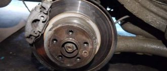
After removing the wheel, I realized that it was necessary to change not only the brake cylinder, but also the pads and brake drum.
In the Avtoall.ru store we purchased VAZ-2101-2112 wheel guide clamps 21013101082 - 4 pieces, link to the product: www.avtoall.ru/fiksator_v..._napravlyayushiiy-003580/, price: 9 rubles per piece.
And the following was purchased at the Planetazhelezyaka.rf store:
— Brake drum IZH-2126 IzhAvto OJSC — 1 piece, link to the product: www.planetazhelezyaka.rf/au…chasti-izh-moskvich/81450, price: 1350 (although when I bought it I took it a little cheaper, apparently the price has risen).
— Rear brake cylinder IZH, M-412 FENOX Classic — 1 piece, link to product: www.planetazhelezyaka.rf/au…chasti-izh-moskvich/73066, price: 565 rubles.
— Brake bleeding key 08x10 with 2 clamps — 1 pc., link to product: www.planetazhelezyaka.rf/avto-instrument/247723, price: 110 rubles.
— brake bleeding hose — 4 meters, internal diameter 4 mm (the hose itself is sold as a hose for windshield washer systems)
— M-2140 rear brake pads, which I don’t remember exactly, cost 450 rubles for a set of 4 pieces.
But I remember how I chose it. To avoid mistakes, I used uncle sergio’s post from the topic about rear pads from the 2126.ru forum.
Specifically the post read:
“so, the promised Smile left block -2140, 412, 2126 middle - 2141 right - 2141 with a re-drilled hole for our finger (test) number 1 - different hole diameters number 4 - attempt to enlarge the hole - pay attention to its location, which is different from the desired one number 2 - a protrusion that distinguishes the pads number 3 - for us this hole is mandatory, unlike the 412th, otherwise we will have to drill (Dafmi pads, for example, without it)"
and below is a comparative photograph of the Muscovite brake pads 2140, 2141 and 2141 drilled out for installation on the Izh 2126.
The pads that are installed on the Izh 2126 without modifications are the ones on the left. The number 2 indicates a characteristic protrusion that makes it easy to remember which pads to buy.
The DOT 4 brake fluid was left over from Oda's clutch bleeding.
- loosen the wheel nuts - jack up the car so that the wheel comes off the ground - do NOT
on a jack, the car must be well fixed (in my case, this role was played by the wheels remaining in the cabin after changing shoes)
- completely unscrew the wheel nuts and remove the wheel - unscrew the old wheel guide clamps (studs) - after this, in theory, the drum should come off, but usually this does not happen, since everything has soured and wear has formed in the drum. In this case, we loosen the handbrake by not just lowering it down, but by unscrewing the tension nuts. And gently and carefully tapping in a circle with a hammer, remove the drum.
— then we disassemble the springs and the pads themselves ( Be sure to remember which sides and what the springs are attached to. It’s even better to take pictures from different angles. Incorrect installation of them can cause a grinding noise when driving and incorrect operation of all brakes.
)
-unscrew the handbrake cable fastening
— unscrew the two bolts securing the brake cylinder on the back side of the brake shield. - next is the fun part, we need to unscrew the brake hose from the brake cylinder using the brake bleeder key. Since there was no desire to repair hoses, the hose was unscrewed as carefully as possible. Namely, half a turn with the key, and then we turn the cylinder itself half a turn, that is, we do not turn the fitting, but the cylinder itself, and so on until we unscrew it. - having installed the new cylinder, also turning the cylinder itself, we assemble everything in the reverse order - be careful there are slots on the cylinder rods, the pads themselves should fit into them - if all the springs are put on easily and without force, most likely you made a mistake and did not install them correctly, check and verify everything again with the photographs - it is also important that brake and oil fluid does not get on the friction linings of the brake pads and the braking surface of the drum; if this happens, you need to carefully wipe it with a cloth with gasoline, but it is better not to allow this as this may have an effect on the operation of the entire brake system - difficulties may arise when seating the drum back, that is, the new pads are wider, plus there is no wear out of the drum, if this happens, it is necessary to loosen the handbrake cable as much as possible in order to compress the pads as much as possible: hit the bracket with a hammer in the direction of the brakes, pull lever in the cabin (the cable must be tensioned, that is, the nuts that we loosened are returned to their place) and so on until the desired result is achieved, before installing the drum, the handbrake cable can be loosened back. — after we have assembled everything, it is imperative to bleed the brakes and adjust the handbrake.
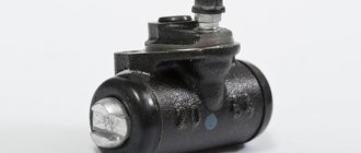
What is a brake cylinder and what is its working principle?
The brake cylinder is one of the main elements of the brake system. The rear brake cylinder body is made of alloy. Do not confuse the rear brake cylinder with the master cylinder. The main brake cylinder is designed to convert brake fluid pressure into fluid pressure, and the rear brake cylinder on the wheel is designed to convert brake fluid pressure into brake pressure on the pad. In other words, the rear brake cylinder presses on the pads, thereby stopping the car.
Features of front and rear wheel brakes
The bolts are placed in the passages of the guide blocks, pressed by the guide spring grooves. A piston with a sealing ring of rectangular cross-section is placed inside the cylinder. This ring provides the most rational distance between the disc and the brake pads. This organization of Kalina's braking system contributes to its efficient functioning.
In addition to the head system, the developers equipped the Lada with a mechanical parking brake, which is driven by the brake mechanisms of the rear wheels.
- adjusting rod;
- lever arm;
- two cables;
- equalizer;
- spacer bars;
- pad drive levers.
Which brake brake should I choose?
The modern market is full of different types of rear brake cylinders, so when buying this element, it is not easy to make a choice. Numerous reviews on the Internet will help us with this. Having studied the content on this topic, we came to the following conclusion: By and large, all brake cylinders in the same price category have the same quality, but the rear brake cylinder from ATE turned out to be the highest quality and most desirable. Our Basalt, which is one of the best domestic manufacturers of these products, does not lag behind.
It’s only recently that I started making quality products. The Belarusian company fenox, whose products are, to put it mildly, “unreliable,” even wanted to buy it, but they couldn’t buy it. The products also perform well.
Signs of a bad rear brake cylinder.
The first and most important sign of a brake cylinder malfunction is a brake fluid leak. But as a rule, the condition of the rear brake cylinder can be fully assessed when removing the drum, so most often it is changed along with replacing the rear pads (How to replace rear brake pads?) and replacing the handbrake cable, which is not good and is fraught with consequences.
Most often, the pistons in the rear brake cylinders become sour, rubber bands break, and the like. In principle, the brake cylinder can be repaired, but it is better to simply replace it with a new one and not waste a lot of time and effort, since the price for them is not outrageous.
How to replace a brake cylinder?
To replace the brake cylinder we will need a jack, wheel wrench, keys, some brake fluid, wd-40.
- First of all, put the car in 1st gear and remove the handbrake.
- We use a balloon to loosen the rear wheel and support the front brakes with “shoes” so that the car does not roll away.
- Place the jack and remove the wheel.
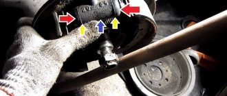
- Unscrew the guide bolts as shown in the figure.
- We try to turn the drum by hand. If this doesn’t work, then take a small sledgehammer and a wooden block and apply the block to the surface of the drum and hit the handle with the sledgehammer. We carry out this operation on the entire surface of the “rim” of the drum until we use our hands to move the drum from its place.
- After turning it 30-40 degrees, screw the guide bolts back into the drum. The purpose of this procedure is to remove the drum.
- After removing the drum, pull the handbrake all the way.
- Then remove the cap of the brake cylinder fitting and use an “8” spanner to unscrew the fitting.
- We carefully treat the brake pipe fitting with wd-40.
- We take the key to “10” and loosen the fitting, after first clamping the tube so that it does not rotate.
- We completely turn out the fitting with the key “10”.
- Using the same key, we unscrew both brake cylinder fasteners.
- We put a rubber cap on the brake fluid pipe.
- We take out the cylinder.
Bleeding Kalina brakes
I will tell you how to bleed the brakes on a Lada Kalina car. The pumping sequence is as follows:
- rear right
- front left
- rear left
- front right
We start with the first wheel in order to bleed (rear right). What will you need for this? Brake fluid (the same as what was poured into the system), a small hose (in my case with a diameter of 5-6mm, about 30 cm long), an empty container for collecting brake fluid, a partner and a set of keys. There should be a special fitting on the back of the wheel for bleeding the brakes. We remove the protective cap from it, put on the hose, and lower the other end into an empty container (a bottle, for example).
Please note here that the brake drum must be on. Otherwise, the resulting pressure when you press the pedal will simply push the pistons out of the brake cylinder and you will have to remove it and reassemble it. IMPORTANT! Bleed the brakes WITHOUT jacking up the wheels, use a pit or overpass. Otherwise, the adjustment of the “sorcerer” (the brake force distributor between the front and rear wheels) will go wrong.
Replacing the rear brake cylinder.
And so, replacing the rear brake cylinder. One day you wake up in the morning and get ready to go to work in a good mood. You open your garage, where your favorite car is, and drive it out of the garage. As you head towards your garage to close the doors, you notice a wet spot on the floor. You leave for work, but you've been bothered all day by that strange spot on your garage floor. In the evening, having quickly examined the car, you do not notice anything strange, but after waiting for the day off, you drive the car into the inspection pit and begin the examination. After a complete inspection, you notice that the brake fluid level in the reservoir has dropped. When you descend into the viewing hole, the following picture is revealed.
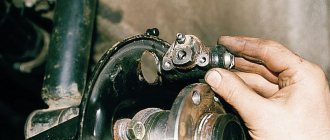
And we immediately understand that the rear brake cylinder needs to be replaced. To replace the brake cylinder, in addition to the usual tool, we will need a special wrench for unscrewing the brake pads.
Next we proceed to replacement.
We jack up the car and remove the wheel. Don't forget to install an additional stop for safety. Remove the brake drum (how to remove the brake drum is described in the corresponding section).
Using a larger screwdriver, remove the brake pads from the lower stops and, lightly pressing on them from above, lower them a little to the bottom so that they release the brake cylinder.
Now we need to unscrew the brake pipe from the cylinder itself. This is where the special key in the photo above comes in handy. With this key we simply rip off the tightened fitting and then unscrew it with a simple key.
When unscrewing, be careful that the fitting does not rotate with the tube, and that you do not accidentally twist the tube. When you unscrew the tube, plug it with a protective cap (from the new brake cylinder) so that the brake fluid does not leak out.
Next, use a regular key to unscrew the two bolts and remove the cylinder itself.
And continuing the topic of replacing the rear brake cylinder, let's talk about the brake cylinder itself.
This cylinder has a built-in system for automatically lining the pads; older models did not have such a system, which added unnecessary hassle with adjustment. I think it’s not worth repairing such brake cylinders; it’s easier to buy new ones.
Next, install the cylinder back and screw on the brake pipe. We put back the pads with the brake drum and screw the wheel. Now all we have to do is bleed the brake system, as described in the corresponding post.
This concludes our article on replacing the rear brake cylinder, and this article will help you replace the cylinder yourself.
Brake system
Device and features
Lada Kalina 2 cars use a working brake system with diagonal separation of circuits, which significantly increases the safety of driving the car. One of the hydraulic drive circuits is capable of providing operation of the front right and rear left braking mechanisms. If the braking system circuit fails, a second circuit is used to ensure the vehicle is stopped safely and efficiently.
A vacuum booster is included in the brake drive. Depending on the configuration, the car is equipped with a pressure regulator for the rear brakes (dual-circuit) or an anti-lock braking system (ABS).
The Lada Kalina is equipped with a cable-type parking braking system on the braking mechanisms for the rear wheels.
The vacuum booster is of the diaphragm type, installed between the pedal mechanism and the main braking cylinder, due to which during braking, due to the vacuum in the engine, in the intake pipe, through the piston in the first chamber of the main cylinder and the curtains, additional force is created, which is proportional to the force transmitted from the pedal. The vacuum chamber is connected to the inlet pipe from the engine via a hose and a check valve, and the atmospheric chamber is connected directly to the atmosphere via a filter when the driver presses the brake pedal. If the brake pedal is released, the atmospheric and vacuum chambers communicate with each other through a special valve.
During braking, the pressure regulator is required to adjust the brake fluid pressure in the working cylinders of the braking mechanisms in the rear wheels, so that the possibility of blocking the rear wheels before blocking the front wheels is eliminated. It is included in both circuits of the braking system, and it is through it that brake fluid flows to the two rear braking mechanisms.
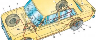
Diagram of a hydraulic brake drive with a dual-circuit pressure regulator for rear brakes: 1 – brake mechanism from the front right wheel, 2 – flexible hose from the brake mechanism for the front right wheel, 3, 4, 15, 18, 21 – pipelines from the rear left – front right circuit wheels, 5, 10, 13, 22, 27 – pipelines from the circuit of the rear right – left front wheels, 6 – reservoir from the main cylinder of the hydraulic brake drive, 7 – main brake cylinder, 8 – vacuum booster, 9, 30 – holders for pipelines, 11 – flexible hose from the braking mechanism for the rear right wheel, 12 – braking mechanism for the rear right wheel, 14, 31 – brackets for fastening flexible hoses, 16 – flexible hose from the braking mechanism for the rear left wheel, 17 – braking mechanism for the left rear wheels, 19 – elastic lever from the braking force regulator drive in the hydraulic drive for the rear brakes, 20 – pressure regulators in the brake hydraulic drive for the rear wheels, 23 – brake pedal, 24 – flexible hose from the braking mechanism of the front left wheel, 25 – braking mechanism from the front left wheel, 26 – tee from the contour of the rear left – right front wheels, 28 – tee from the contour of the rear right – front left wheels, 29 – bolts for fastening the tees.
The pressure regulator 1 is secured to the bracket 9 using two bolts 16 and 2. At the same time, the fork bracket 3 from the lever 5 of the regulator drive is also attached to the front bolt 2. A double-arm lever 5 is hingedly attached to the finger of this bracket using a pin 4. Its upper arm is connected to the elastic lever 10, and its other end is connected through the earring 11 to the bracket on the rear suspension arm. Bracket 3 together with levers 5, thanks to the presence of oval holes for fastening bolts, can move relative to the regulator. In this way, the force with which lever 5 is able to act on the control piston is regulated.
The adjuster has four chambers: A and D connect to the main cylinder, B to the left, and C to the right wheel cylinders from the rear brakes.
When the brake pedal is in its original position, the piston 2 is pressed by the lever through the leaf spring 7 to the pusher 20, which, under a given force, is pressed to the seat 14 from the valve 18. At the same time, the valve 18 is pressed away from the seat, forming a gap P and a gap K between the piston head and seal 21. Thanks to these gaps, the A and D chambers, the B and C chambers, are connected and communicated.
When the brake pedal is in the clamped position, the fluid enters the working cylinders of the braking mechanisms through the H and K gaps, as well as chambers C and B. When the fluid pressure increases, the force on the piston also increases, which tends to move it out of the housing. When the force from the pressing fluid exceeds the force from the elastic lever, the piston begins to gradually protrude from the body, and behind it, under the influence of springs 17 and 12, the pusher 20 will move together with the sleeve 19 and rings 10. The gap M increases, the gaps K and decrease H. When the H-gap is completely selected, and valve 18 completely isolates chambers D and C from each other, pusher 20, together with the parts located on it, will stop moving after the piston. And from this moment on, the pressure in the C-chamber will change depending on the pressure in the B-chamber. If the force on the brake pedal continues to increase, the pressure in chambers A, B and D will increase, piston 2 will continue to move out of the body, and sleeve 19 together with O-rings 10 and plate 11 will move into side of the plug 16. The M-gap will begin to decrease. Due to the decreasing volume of chamber C, the pressure inside it, and therefore also in the brake drive, will increase, almost becoming equal to the pressure created in chamber B. When the K-gap is equal to zero, the pressure in the B-chamber, and therefore in chamber C will not increase as actively as the pressure in chamber A, due to the throttling of the liquid between the seal 21 and the piston head itself.
If the vehicle load increases, the elastic lever 10 is loaded more, and the force from the lever 5 on the piston also increases, which means that the moment of contact of the seal 21 with the piston head can be achieved if there is greater pressure in the main brake cylinder. This means that the effectiveness of the rear brakes increases as the load increases.
If the front left-rear right brake circuit fails, the O-rings 10, as well as the bushing 19, due to the fluid pressure in the B-chambers, will shift towards the plug 1 until the plate 11 rests on the seat 14. The pressure in the rear brake will be regulated by that part of the regulator , which includes piston 2 with a seal. And also bushing 7. The operation of this part of the regulator in the event of a failure of the above-mentioned circuit turns out to be similar to the operation if the system is working properly. The nature of the change in pressure at the outlet of the regulator turns out to be the same as in the case of serviceability of the entire system.
In the event of a failure of the front right-left rear brake circuit due to brake fluid pressure, the pusher 20 with the bushing 19 and sealing rings 10 will be shifted towards the piston in order to push it out of the housing. The M gap will increase and the H gap will decrease. When seat 14 touches valve 18, the increase in pressure in the C-chamber will stop, which means that in this case the regulator will act as a pressure limiter. In this case, the achieved pressure values will be sufficient for reliable operation of the rear brake.
There is a hole in housing 1 that is closed using plug 24. Leakage of liquid from under the plug during its extrusion may indicate a leaky connection of rings 10.
Hydraulic brakes with anti-lock system (ABS): 1, 14, 22 – brackets for fastening flexible hoses, 2 – brake mechanism from the front right wheel, 3 – flexible hose from the brake mechanism for the front right wheel, 4, 5, 15, 18, 26 – pipelines from the circuit of the front right – rear left wheels, 6, 10, 13, 27, 28 – pipelines from the circuit of the front left – rear right wheels, 7 – reservoir from the main cylinder of the hydraulic brake drive, 8 – vacuum booster, 9, 24 – holders from pipelines, 11 – flexible hose from the brake mechanism of the rear right wheel, 12 – brake mechanism from the rear right wheel, 16 – brake mechanism from the left rear wheel, 17 – flexible hose from the brake mechanism for the rear right wheel, 19 brake pedal, 20 – brake mechanism from the front left wheel, 21 – flexible hose from the brake mechanism for the front left wheel, 23 – main cylinder of the hydraulic brake drive, 25 – gyroelectronic ABS module.
Vacuum booster: A – vacuum chamber, B – atmospheric chamber, C, D – channels, 1 – flange for fastening the tip of the check valve, 2 – rod, 3 – return spring from the diaphragm, 4 – O-ring from the main cylinder flange, 5 – main cylinder, 6 – stud from the amplifier, 7 – housing from the amplifier, 8 – diaphragm, 9 – cover from the amplifier housing, 10 – piston, 11 – protective cover from the housing for the valve, 12 – pusher, 13 – return spring from the pusher, 14 – spring from the valve, 15 – valve, 16 – buffer from the rod, 17 – body from the valve.
Drive from the pressure regulator: 1 – pressure regulator, 2, 16 – bolts for fastening the regulator, 3 – bracket from the lever to drive the regulator, 4 – pin, 5 – lever from the regulator drive, 6 – axis from the lever to drive the regulator, 7 – spring from the lever, 8 – bracket from the body, 9 – bracket for fastening the regulator, 10 – elastic lever from the regulator drive, 11 – earring, 12 – bracket from the earring, 13 – washer, 14 – retaining ring, 15 – pin from the bracket, A, B, C – holes.
The main brake cylinder is of the “tandem” type, the hydraulic brake drive is installed in the engine compartment on the brake vacuum booster itself.
It consists of two separate chambers, which are connected to independent hydraulic circuits. The first camera communicates with the front right and rear left braking mechanisms, and the second - with the front left and rear right.
It is installed on the main cylinder by means of rubber connecting bushings and secured to the cylinder using plastic holders of the tank, the internal cavity of which is divided by partitions into two separate compartments. Each of these compartments feeds one of the chambers of the main braking cylinder.
When the brake pedal is pressed, the pistons of the main braking cylinder begin to move, block the compensation holes with their working edges from the cuffs, and the reservoir and chambers are separated so that the displacement of the brake fluid begins.
A sensor is installed at the top of the reservoir itself, indicating the brake fluid level. If the fluid level drops below the permissible level, the instrument cluster issues a signal of a faulty state of the braking system. The flange connecting to the vacuum booster for braking is sealed with a special rubber ring.
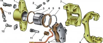
The front wheel braking mechanism is disc, equipped with automatic adjustment of the gap between disk 10 and pads 7, and has a floating bracket. Such a movable bracket is formed using a caliper 8 with a single-piston working cylinder. Guide 9 from the pads is bolted to the steering knuckle. The movable bracket is attached with bolts to guide pins 4, which are installed in the guide holes from the pads. The guide pins are lubricated with grease and are also protected by rubber covers 5. A piston with an O-ring is installed in the cavity of the worker cylinder. Thanks to the elasticity of this ring, it is possible to maintain optimal clearance between the ventilated disc and the pads. During the braking process, the piston, due to the influence of fluid pressure, presses the inner pad to the disc, the result of the reaction force is the movement of the caliper on the fingers, and the outer pad is also pressed against the disc, and the pressing force of the pads is similar. When the brake release occurs, the piston, due to the elasticity of the sealing ring, is removed from the pad, and an oversized gap is formed between the disc and the pads.
The rear wheel braking mechanism is drum-type and is equipped with automatic adjustment of the gap between the drum and the shoes. Brake pads 4 and 11 are actuated by one hydraulic working cylinder 8 and two pistons. The optimal gap between the pads and the drum is maintained thanks to mechanical regulators, which are located in the working cylinder and are split elastic thrust rings made of steel, installed in the cylinder with interference.
Pressure regulator: 1 - body from the regulator, 2 - piston, 3 - protective cap, 4, 8 - retaining rings, 5 - bushing from the piston, 7 - bushing from the body, 9, 22 - support washers, 10 - sealing rings from the pusher , 11 – support plate, 12 – spring from the pusher bushing, 13 – sealing ring from the valve seat, 14 – valve seat itself, 15 – sealing gasket, 16 – plug, 17 – valve spring, 18 – valve, 19 – bushing from the pusher , 20 – pusher, 21 – seal from the piston head, 23 – seal from the piston rod, 24 – plug, A, D – chambers that connect to the main cylinder, B, C – chambers that connect to the wheel cylinders from the rear brakes, K, M, N – gaps.
Main brake cylinder: 1 – cylinder housing, 2, 3 – pistons for driving the brake circuits, 4 – spacer washer, 5 – pusher.
Shaped shanks from the pistons fit into shaped holes in the thrust rings. As the pad linings wear out, the thrust rings move along the mirror from the cylinder in its holes on the outside to allow the pistons to similarly move further outward and limit their movement back into the cylinder due to the action of the return springs, thereby compensating for the increasing gaps between the drum and the pad linings brake
Front wheel brake mechanism: 1 – brake hose, 2 – air release valve, 3 – working cylinder, 4 – guide pin, 5 – protective cover for the guide pin, 6 – brake shield, 7 – brake pads, 8 – caliper, 9 – guide from the pads, 10 – brake disc.
The parking braking system is mechanically actuated and consists of a lever 2, which is installed on the base of the body between the front seats, a rod 4 with an adjustment device and an equalizer 5, to which 2 cables are connected. The tips 12 from the cables are connected to the expansion levers 10 of the braking mechanisms for the rear wheels. When tensioned, the cable from the parking brake turns the expansion lever 10, and through the spacer bar 11 presses the front shoe to the brake drum. When a rigid stop is obtained thanks to the spacer bar, the expansion lever presses the rear brake shoe against the drum.
Lever 2 is fixed in a raised position thanks to a ratcheting mechanism, which consists of a pawl with a toothed sector. When the lever is raised, the switch, which is located on the bracket for mounting the lever, turns on the warning lamp in the instrument cluster. When the parking brake lever is lowered, the shoes move away from the drum due to the action of the tension springs. During use, the parking brake does not require special care.
The emergency brake fluid level sensor is of the mechanical type. The housing 2 from the sensor with the seal 4, as well as the base 3 with the reflector 6, are pressed using a protective ring 5 to the neck pipe of the tank itself. When the brake fluid level in the reservoir drops to the maximum permissible level, contacts 11 and 10 of the sensor close the circuit from the warning lamp in the instrument cluster.
The anti-lock braking system (ABS) consists of wheel speed sensors, a switch for brake lights, a gyroelectronic control unit, and a warning light. In addition, the anti-lock braking system is equipped with a special self-diagnosis system that independently identifies all malfunctions of all its components, and also provides functions for maintaining operation even in the presence of system failures.
ABS is designed to regulate the pressure in the braking mechanisms of all wheels in cases of braking under difficult road conditions in order to prevent wheel locking.
The operating modes of the anti-lock braking system are described in articles about the “Security System”.
To diagnose and repair the anti-lock brake system, you need tools and special equipment. In this case, if it fails, you should contact a specialized maintenance service.
The hydraulic brake system is combined into a single whole using metal tubes and hoses. The system is filled with DOT-4 brake fluid.
Braking mechanism from the rear wheel of a car with ABS (in the illustration the drive disc and drum are removed): 1 – spacer bar, 2 – wheel speed sensor, 3 – clamping spring, 4 – front brake pad, 5 – spring from the parking brake cable, 6 – bottom spring from the coupling shoes, 7 – shield from the brake mechanism, 8 – working cylinder, 9 – pin from the parking brake drive lever, 10 – expansion lever from the parking brake drive, 11 – rear brake shoe, 12 – tip from the drive cable parking brakes
Drive of the parking brake system: 1 – button for fixing the lever, 2 – lever from the parking brake drive, 3 – protective cover, 4 – rod, 5 – equalizer for the cable, 6 – adjusting nut, 7 – locknut, 8 – cable, 9 – cable sheath.
Emergency brake fluid level sensor: 1 – protective cap, 2 – sensor housing, 3 – base of the sensor itself, 4 – sealing ring, 5 – clamping ring, 6 – reflector, 7 – pusher, 8 – bushing, 9 – float, 10 – fixed contacts, 11 – moving contact.
Useful tips
The working stroke of the brake pedal with the engine running should be approximately 65-60 mm. A smaller stroke may indicate incorrect initial installation of the brake pedal, a violation of the adjustment of the brake vacuum booster or jamming of the working cylinder, which may cause increased fuel consumption and accelerated wear of the brake pads. An increased stroke may be a sign of excessive clearances in the pedal mechanism or a leak in the hydraulic drive of the braking system. If the reduction in stroke occurs due to repeated pressing of the pedal, that is, it becomes “harder,” air is detected in the system. If the tight pedal stroke increases, then the system becomes leaky. If during braking the brake pedal constantly begins to vibrate, this is most likely due to warped brake discs. In this situation, unfortunately, they can only be replaced, and both at once.
If the car begins to pull to the side during braking, you should check the working cylinders: they may need to be replaced.
If a knock appears in the front suspension, which disappears when braking, you should check whether the bolts securing the caliper are tightened well.
After replacing the brake pads and before starting to move, you should press the brake pedal repeatedly: then the pistons in the working cylinders must fall into place.
How to remove and install the rear brake cylinder on a VAZ 2114, 2113, 2115
The rear brake cylinder is responsible for effectively braking your car. Therefore, you need to check its operation from time to time. After all, your safety on the road depends on it. It is located under the rear wheel drum. To gain access to it, you need to remove the wheel and pull out the drum.
Selecting a brake cylinder.
Today there are a huge number of manufacturers of spare parts for cars. And it’s easy to get confused when choosing quality spare parts. In order to make a choice, you can read reviews on the Internet. We also read and came to certain conclusions. The most reliable brake cylinder is considered to be the ATE cylinder. The cylinder is also not inferior to it. You can also look at Kraft products.
How to determine a faulty brake cylinder.
The first sign of a problem in the brake system will be a brake fluid leak. You can also evaluate the condition of the cylinders when replacing the rear pads. Usually the rubber bands in the brake cylinders break and the pistons become sour. Of course, they can be repaired, but it is much easier to replace them with new ones, since they are not expensive. In stores you can find cylinders for around 400 rubles.
Principle of operation
The operating principle of the Lada brake system is as follows. After pressing the brake pedal, the piston begins to move in the cylinder. Fluid from the main exhaust valve enters the Kalina brake system through hydromechanical hoses. The fluid is then directed towards the main wheel mechanism through pipelines, creating the necessary conditions for the movement of the pads to the front wheel disks and to the rear drums. Contact occurs and braking occurs.
- Presence of air in the system. You can solve the problem not only with service, but also yourself. To do this, you need to bleed the brakes.
- Brake fluid leaking. This situation indicates a malfunction of pipelines and rubber hoses.
- Increasing pedal stroke. The problem that has arisen indicates a problem with the vacuum booster. It is recommended to replace the hose and check its attachment points.
- Reduced braking efficiency. In this case, the reason may be oily brake linings, jammed cylinder pistons, compromised gasket integrity, or defective adjustment by the regulator.
- Squeaking or vibration when braking. Perhaps the tension spring is weakened, the linings are out of order, or the rubbing linings are oily.
Replacing the rear brake cylinder.
- The first step is to remove the brake drum.
- Raise the handbrake all the way.
- Remove the cap from the bleeder fitting and use a size 8 wrench to completely unscrew it.
- Lubricate the fitting with grease.
- Loosen the brake pipe fitting.
- We finally unscrew the fitting.
- Unscrew the 2 bolts securing the working cylinder.
- Place the fitting cap on the tube to prevent brake fluid from leaking out.
- Remove the brake cylinder from the shield.
- Before installation, we clean everything from rust and dirt and degrease the working surfaces.
- Reinstall the brake cylinder in reverse order.
- Reinstall the brake drum.
We bleed the brake system and check everything for leaks.
Replacement algorithm
The process of replacing brake pads on cars with and without ABS has only one difference. In cars with ABS, you should disconnect the wires from the sensors before starting work to avoid damaging them.
The replacement process is carried out in several stages:
- We install wedges under the front wheels.
- We lower the handbrake as much as possible, which will reduce the tension of the cable.
- Additionally, we loosen the handbrake cable by turning the adjusting bolt, accessible from the bottom of the car.
- Now you need to jack up the wheel.
- Take the wheel wrench and unscrew the wheel bolts. Next, remove the wheel.
- Unscrew the pins with a 7 key.
- Using a metal brush, clean the rear wheel hub in the place where the drum is located.
- Apply WD-40 to the drum landing area, then wait a few minutes.
- To make it easier to remove the drum, you must first tap it with a rubber hammer.
- Now we gradually screw the M8 bolts into the holes of the drum, which will allow it to be removed from the hub.
- During a visual inspection, you must make sure that the drum does not have chips, cracks or other defects. If traces of uneven wear are found on a part, it should be replaced.
- Using mounting blocks, we bring the rear pads together.
- We take a regular screwdriver and pry off the end of the upper spring that tightens the pads. Carefully remove it from engagement with the block.
- Remove the upper spring.
- Using pliers, release the lower tension spring from its socket and remove it.
- Remove the front pad.
- We remove the spacer bar.
- Now you need to remove the parking brake cable end. It is located on the hook of the spacer lever of the far block.
- We take the pliers again and release the spring holding the rear block.
- We remove the block.
- Remove the spacer lever.
- We take a rag and clean the parts from dirt.
- We install the spacer lever on the new block.
We perform the steps to assemble the unit in reverse order.
It is convenient to tighten the pressure spring using a hook or a piece of wire.
Differences between brake pads with and without ABS. For the version with ABS, a recess for the sensor is required.
WITHOUT ABS
- LADA 21080-3502090-55
- ADR 010821
- TRIALLI GF 231
- PILENGA ITALY BS-T 1002
- FORTECH FB-2102R
- FINWHALE VR318
- LUCAS/TRW GS8210
- BREMBO S 41 503
- VALEO 562067
- SANGSIN SA183
LADA 21080-3502090-55 - without ABS. Original pads.