High-voltage automotive wires are the connecting link between the throttle (or ignition unit) and the spark plugs, serving to transmit a powerful electrical impulse that ignites the working mixture. Their malfunction immediately affects not only the condition of the spark plugs, but also the operation of the engine itself. Today we will tell you how the high-voltage wires of the VAZ 2114 are arranged, and how to replace them with your own hands if necessary.
Armored wires VAZ 2114
High-voltage wires VAZ 2115
Automotive high-voltage (HV) wires play an important role for internal combustion engines, since they help transmit high current from the ignition coil to the spark plugs. The serviceability and efficiency of the wires determines the timeliness and intensity of ignition of the fuel-air mixture, and therefore the correct and uninterrupted operation of the engine. Despite their simplicity, wires have many different “sores” and can cause a lot of troubles to their owner, which in one way or another will affect his nerves and pocket.
Connection
The order of connecting high-voltage wires must be strictly sequential, since each cylinder of the engine corresponds to a specific socket on the ignition module. Considering that there is a numbering of the sockets on the ignition module body, the risk of confusing anything is minimal.
The procedure for connecting high-voltage wires of the VAZ 2114 injection type depends on the year of manufacture of your car. Fourteen cars before 2004 had 4-pin ignition modules installed, and cars after 2004 had 3-pin coils.
The connection diagram for VAZ 2114 high-voltage wires to the ignition module (until 2004) is as follows:
Connection diagram for VAZ-2114 with ignition coils (after 2004):
In the pictures you can see the numbers of the landing slots. Each number must have a corresponding cylinder connected to it (cylinder numbering is counted from left to right).
To correctly install high-voltage wires on the VAZ 2114, follow the following algorithm of actions:
— Turn off the ignition. Open the hood and remove the power terminals from the battery;
— We remove the old GDPs from the mounting sockets on the module and cylinders;
— We remember the location of the high-voltage wires of the VAZ 2114 and connect new GDPs according to the diagram. Before replacing, it would not be amiss to draw this very diagram by hand on paper so as not to confuse anything;
— We connect power to the battery and, to check whether we did everything correctly, start the engine.
When installing the wiring, do not try to connect individual air intakes to each other with plastic clamps; to do this, you must use the comb holder that comes with them. A thin clamp can easily wear through the insulating coating. Also make sure that the GDP does not bend.
Connecting armored wires on VAZ 2115 and 2113 is carried out in a similar way.
How to remove high-voltage wires?
Turn off the ignition. Open the hood. Pull out the wires from the ignition module and from the engine.
How to connect high voltage wires?
The BB wires must be connected in a certain order. Each wire goes to a specific cylinder and to a specific connector in the ignition module (ignition coil). There are markings both on the wires and on the ignition module. But without removing the module, the markings cannot be seen, so see the photo below.
Connection diagram for high-voltage wires:
Cylinder numbering from left to right. Ignition module numbering: first cylinder - lower left compartment of the ignition module
Second cylinder - upper left compartment
The third cylinder is the upper right,
The fourth cylinder is the lower right compartment of the ignition module.
Location
Incorrect installation and location of high-voltage wires can lead to a spark jumping from wire to wire or to ground, which, in turn, can lead to misfires and a decrease in the crankshaft speed when the car is moving at high speed.
Therefore, install the high voltage wires properly as shown in the pictures above.
Disconnect the high-voltage wires from the spark plugs and ignition coils. Clean and check the integrity of the insulation of high-voltage wires. Check the internal contact surfaces of high-voltage wires for corrosion or carbon deposits.
Use an ohmmeter to measure the resistance of the high-voltage wires.
Checking the main relay in a Lada Samara car
The prices for such devices in car dealerships are minimal, but their importance cannot be denied, since they largely affect the performance of electrical equipment. F8 7.5 A.
The cost of these elements in stores is minimal, but they play a very important role and must always be in working order. The box is designed for three relays and three 15A fuses, and is covered with a plastic shield on top.
The exterior decoration was decorated with plastic elements, since metal ones were corroded by corrosion.
In the instrument panel wiring harness, the second ends of the white wires are brought together into one point, which is connected to the instrument lighting switch except for the white wire, from plug “4” of block “X2” of the mounting block 28 to the display block 83 of the on-board control system.
However, in general, the VAZ model remains the same - it is equipped with front-wheel drive and five doors.
Give preference to new models. Despite modernization, many motorists who are far from the domestic automobile industry are still confused and
Fuses do not protect only: the ignition circuit; electrical circuit for powering the generator and starter. How to check the ignition module, ignition coil and armored wires?!
Functions and tasks
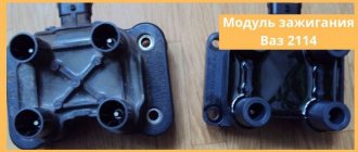
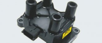
The module supplies high voltage to the spark plugs through the PVN. PVN are high voltage wires . Before completely changing the module, make sure that the high-voltage wires on the VAZ 2114 do not need to be replaced. Otherwise, you will waste your money.
When the module is operating, current is supplied to the spark plug. As you know, there are two of them in the car. If one is supplied with a working spark, then the second is supplied with an idle spark. The working charge is intended for cylinders 1 and 4, and the idle charge is for cylinders 2 and 3. This scheme allows the spark to be in the required cylinder during the corresponding engine stroke.
BB: what do they look like?
High-voltage wires VAZ 2114
Naturally, the technical conditions for the existence of working wires are the conditions of a permanent conductor. If we add here temperature changes and the imperfection of our world, we get the fact that the contact system fails within a certain period of time. And it comes with a frequency of 30,000 km.
This is a control figure that tells you when to change high-voltage wires. The fact is that over time, internal resistance begins to increase in them, preventing the impulse from passing as it should. In this case, you may notice the following behavior of the fourteenth:
- You want to press your sneakers to the floor, but the engine doesn’t respond
- The engine may simply stall
- At idle the engine troits
- It often happens that car owners themselves do not notice how high-voltage wires are pierced
Of course, this is not an indicator of a malfunction only in high-voltage equipment, but there is a high probability that it was they who flew. Surely, it is worth carrying out a test procedure for all contacts.
And the tester showed that the wires had a long life. Well, the high-voltage wires on the VAZ 2114 need to be replaced. The procedure, in principle, is not troublesome. If you were able to test them, then you can replace them. The main thing is to understand the order of connecting high-voltage wires.
The fourteenth is an improved version of the nine, it has higher ignition power. Therefore, contacts have been added to the four high-voltage wires for connection to the ignition terminal itself, through which a signal goes to the spark plugs; Also, in the fourteenth system there are contacts leading to the switch, as well as contacts for connecting the adsorber valve to the gasoline injection system control unit.
The procedure for connecting high-voltage wires to a VAZ 2114
The connection diagram for high-voltage wires is quite simple:
- Cylinder 1 clings to the lower left contact
- Cylinder 2 clings to the upper left contact
- Cylinder 3 clings to the upper right contact
- Cylinder 4 clings to the lower right contact
This is sometimes called module bay interface in schematics. Essentially, everything is correct. The main thing is to understand that all cylinders are counted from left to right, like any count adopted from the logic of writing from left to right: 1,2,3,4. And the connection is obtained according to the following scheme: 1,3,4,2. Many people sketch and write down how the contacts were before removal. But, if you look at the module itself, there are docking numbers there. It's impossible to make a mistake.
Signs of breakdown
A malfunction of the ignition coil, or rather the module, can be determined by several characteristic signs:
- When accelerating, the car seems to fall through, there is a sharp short-term loss of power;
- The overall engine power level drops;
- Unstable behavior of the car when idling;
- The engine is shaking, which indicates cylinder failure.
Before you begin repairing the module, make sure that the spark plugs on your VAZ 2114 do not need to be replaced. Perhaps they have lost their effectiveness, the contacts have become clogged, or simply the life cycle of this component has come to an end.
High-quality spark plugs for a VAZ 2114 car with an 8-valve injection engine are not expensive, so you will not experience serious financial losses. But the ignition system and engine will work more efficiently.
But if the problem is still in the module, it is recommended to check the contacts. Most often, the basis for failure of the ignition module is the lack of quality contact. Sometimes they oxidize, stick, and the mass breaks off. Even if a layer of dust appears on the cylinder, it can fail.
Service Manual
To ensure that electrical work does not cause trouble, the car owner must at least understand the electrical circuit of the VAZ. If a malfunction occurs in the operation of a particular equipment, using a diagram you can find out what the problem is and where to look for the cause. In some cases, a problem in the operation of certain devices can be solved by reconnecting the plug (if we are talking about poor contact of the device with the electrical network).
In practice, our compatriots often encounter problems with the operation of relays - the contact legs of these components can burn out as a result of voltage surges in the electrical network. Even if the relay legs are intact, but the equipment does not work, the device must be dismantled and disassembled - perhaps the contacts are burnt inside. If necessary, they can always be cleaned with a wire brush or sandpaper.
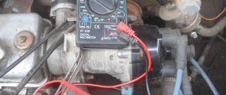
To prevent the battery from discharging, the battery must be recharged from time to time, especially before the onset of cold weather and at the end of winter. During the cold season, batteries discharge the fastest; this happens due to frost, so with the onset of winter, car owners often face the problem of starting the engine in the morning. If you doubt the battery's performance, you can try testing it with a multimeter; to do this, connect the tester probes to the battery terminals. Ideally, with the engine running, the battery voltage should be between 13.5 and 14 volts. If the resulting value is less or more, this indicates that the battery is not operating correctly.
Error codes
When diagnosing a car at a service station or if you have the appropriate equipment, you can determine some malfunctions of the ignition module.
There are several codes that will be very useful for you:
- If the coil of cylinders 1 and 4 breaks, the device will display error P0351;
- If there is a break on cylinders 2 and 3, the error code will be P0352;
- Code P3000-3004 indicates multiple misfires.
It would be a good idea to fully check the ignition module. The simplest diagnostics involves measuring the resistance between wiring of cylinders 1 and 4 and cylinders 2 and 3 with a multimeter. First switch the device to ohmmeter mode. If the indicator was 5.5 units. then everything is fine with your module.
Although there are three more ways to check:
- Check the wiring harness. Disconnect it and check with a voltmeter. The probe is directed to contact A, and the second to engine ground. Start the engine and check the indicators. A good indicator is about 12V. If there is no voltage, the coil may be faulty.
- Examine the condition of the high-voltage wires with an ohmmeter. If the high-voltage circuits are installed incorrectly, the module will simply burn out.
- Pull the block with the wires a little and tap on it. Contacts should not be lost in this case. If the opposite happens, this indicates bad contacts that can completely break off at the most inopportune moment in the very near future.
How to check the ignition coil?
The ignition coil consists of two electric coils, which are controlled by the engine controller. It serves to convert low-voltage 12-volt voltage into high-voltage to produce a spark.
Typical unit malfunctions
The short circuit is a reliable unit with a long service life, but it can fail.
Signs of a short circuit fault:
- engine power decreases;
- failures at certain speeds;
- misfires;
- high fuel consumption;
- work with jerks at idle;
- coil overheating due to internal short circuit;
- The Check Engine light comes on.
Based on these signs, it is impossible to say for sure that the short circuit is faulty. Therefore, its diagnosis is necessary.
Module replacement
Replacement is a fairly common solution to the problem of a faulty ignition module. The procedure is performed as follows:
- Locate the ignition module. If anything, high voltage wires go from the spark plugs to it. You can't go wrong;
- Remove the negative terminal from the battery;
- Disconnect the wiring block from the ignition module;
- Turn off the high voltage;
- Dismantle the module and remove it;
- Place a new coil, or rather a module, in place of the old device, and reassemble in the reverse order;
- Please do not confuse the location of the high voltage wires on the module, otherwise you will have to buy a new component;
- For preventive purposes, it would not be a bad idea to replace the old wires. Especially if there are yellow stripes on the tips of the spark plugs and on the wiring themselves. This is clear evidence that the elements must be replaced.
Demonstration of replacement using the example of a VAZ 2112
If you do not want to completely change the module, you can try to bring it back to life by repairing it. The task is not too difficult, so doing it yourself is more than possible.
- Arm yourself with 17, 13 and 10 mm socket wrenches, a screwdriver, a soldering iron, aluminum flux, nail polish, stranded wires and a 5mm hex wrench.
- The weakest point of the ignition module is the contacts.
- Start the car, pull the contacts. This will help determine if the problem really lies with poor connections.
- Stop the engine and remove the module. We told you how this is done in the previous section.
- Open the module by simply prying up the housing with a flat-head screwdriver.
- Inside there is a board with silicone film. Clean it up.
- Remove aluminum from explosive contacts.
- Now comes the most difficult stage - working with a soldering iron. The task is to solder the new wires to the place where you just removed the old ones.
- Clean the surfaces from deposits, place the board on the stove and heat it to approximately 200 degrees. You can determine the desired heating level by a slight smell.
- Start soldering. The ends of the wires are connected to the module.
- Treat the resulting new contacts with regular colorless nail polish.
- Reassemble the module in reverse order, turn on the ignition.
- If everything works well, arm yourself with sealant and glue everything as firmly as possible.
- If a transistor or switch fails, it will be impossible to repair it. These elements can only be fully replaced. But don’t worry, because their price is approximately 200-300 rubles. That is, purchasing new elements will cost a total of 500 rubles maximum.
As you can see, solving the problem with the ignition coil on the VAZ 2114 is not at all difficult. Try to remember that module and coil are synonymous. But for the “fourteenth” VAZ it is still correct to use the concept of ignition module.
But again, it all also depends on the engine used. If a specific module is used for a 1.5-liter old engine, then coils are installed on 1.5 and 1.6-liter engines of the new generation.
Installing an electronic BSZ instead of a contact one
Today it is very rare to find a “seven” with contact ignition. With the arrival on sale of switches, distributors and coils for electronic spark generation systems, owners of classics began to massively re-equip their cars.
What is included in the BSZ kit
The process of converting a contact system into an electronic one is quite simple, and also inexpensive. The cost of an electronic ignition kit for a VAZ 2107 is about 2,500 rubles. It includes:
- transistor switch type 3620.3734 with connector;
- coil 27.3705;
- contactless distributor type 38.3706;
- connecting wires.
In addition, you will need spark plugs (preferably new ones) with a gap of 0.7–0.8 mm and a set of high voltage wires. Coil type B-117A (used in a contactless system) is not suitable for electronic ignition. Its characteristics do not correspond to those of other equipment in the circuit.
Video: review of BSZ elements for “classics”
Required Tools
To complete the work you will need:
- 8, 10 and 13 mm wrenches;
- screwdriver with a Phillips blade;
- drill;
- spark plug key;
- 36 mm wrench or with a ratchet mechanism for turning the crankshaft;
- self-tapping screws;
- pliers.
- Disconnect the terminals from the battery. We remove the battery and put it aside.
- Remove the high voltage caps from the distributor cap and from the spark plugs.
- Using a special wrench, unscrew all the spark plugs. We screw new ones in their place.
- Using a drill, drill holes on the left mudguard or on the engine shield to mount the switch.
- We attach the switch to the car body using self-tapping screws.
- Remove the distributor cap.
- We rotate the crankshaft, placing a wrench on the nut securing its pulley, until the distributor runner is aimed at the spark plug of the first cylinder, and the mark on the pulley points to the middle ebb on the timing cover.
- Using a 13 mm wrench, loosen the distributor mounting nut.
- Remove the vacuum hose from the distributor and disconnect all wires.
- We remove the old distributor from its seat.
- Remove the cover from the new distributor.
- Trying it on in place of the old one, we rotate the slider by hand until it is directed towards the first cylinder.
- We install a new distributor, tighten the nut, but do not tighten it completely.
- We connect the wire connectors and the vacuum regulator hose to the new distributor.
- We dismantle the old ignition coil by unscrewing the nuts securing it with a 13 mm wrench. We disconnect all wires from it.
- We install the new coil in place.
- We connect the connector with the wiring harness to the switch.
- We clean the ends of the wires. We install the chain:
- We securely attach the black wire from the switch to ground using a self-tapping screw or screw;
- connect the red wire to terminal “K” on the coil. We also attach the brown wire from the tachometer here;
- connect the blue wire from the switch and the blue wire with a black stripe to the “+B” terminal on the coil.
- We install the distributor cover and secure it. We connect new high-voltage wires to the cover and spark plugs.
- Let's try to start the engine. If it works, then everything was done correctly. Otherwise, we check the ignition circuit and the reliability of the connection of its elements.
Connection features
The order of connecting high-voltage wires must be strictly sequential, since each cylinder of the engine corresponds to a specific socket on the ignition module. Considering that there is a numbering of the sockets on the ignition module body, the risk of confusing anything is minimal.
The procedure for connecting high-voltage wires of the VAZ 2114 injection type depends on the year of manufacture of your car. Fourteen cars before 2004 had 4-pin ignition modules installed, and cars after 2004 had 3-pin coils.
The connection diagram for VAZ 2114 high-voltage wires to the ignition module (until 2004) is as follows:
Connection diagram for VAZ-2114 with ignition coils (after 2004):
In the pictures you can see the numbers of the landing slots. Each number must have a corresponding cylinder connected to it (cylinder numbering is counted from left to right).
To correctly install high-voltage wires on the VAZ 2114, follow the following algorithm of actions:
- Turn off the ignition. Open the hood and remove the power terminals from the battery;
- We remove the old GDPs from the mounting sockets on the module and cylinders;
- We remember the location of the high-voltage wires of the VAZ 2114 and connect new GDPs according to the diagram. Before replacing, it would not be amiss to draw this very diagram by hand on paper so as not to confuse anything;
- We connect power to the battery and, to check whether we did everything correctly, start the engine.
When installing the wiring, do not try to connect individual air intakes to each other with plastic clamps; to do this, you must use the comb holder that comes with them. A thin clamp can easily wear through the insulating coating. Also make sure that the GDP does not bend.
Connecting armored wires on VAZ 2115 and 2113 is carried out in a similar way.
How often should GDP be changed?
According to the recommendations of Avto-VAZ, replacement of high-voltage wires of the VAZ 2114 should be done every 30 thousand kilometers. In practice, motorists rarely comply with these replacement deadlines, since if the wires do not have any mechanical damage, they can travel about 100-150 thousand km.
When the service life is exceeded, the internal resistance of the GDP increases, which negatively affects the transmission of the electrical impulse. This leads to problems with ignition and acceleration dynamics, since when the supply of current to the spark plugs is delayed, the normal engine operating cycle is disrupted.
Change the wires every 25-30 thousand and everything will be fine
Functionality check
To accurately determine whether it is time to change the high-voltage wires of the VAZ, you need to check their performance with a multimeter.
This operation will take you no more than 15 minutes:
- Turn off the ignition;
- We remove the wires: disconnect the first end from the ignition module, the second from the cylinder;
- We switch the tester to ohmmeter mode and connect the multimeter probes to the wire contacts.
If the high-voltage wires on the VAZ 2114 are in normal technical condition, the multimeter will show a resistance within the value indicated on the wire insulation; if the readings are different, the armored wires on the VAZ 2114 need to be replaced. The process must be repeated on each wire in turn.
If the test shows disappointing results, there is a possibility that the problem of increased resistance lies in oxidized contacts. In this case, you can try to revive the VVP by wiping the contacts with VD-40 or carburetor cleaning fluid.
Also, the cause of problems with ignition can be a breakdown of the GDP. You can determine it visually in the dark - take a flashlight and open the hood of the fourteenth, find and inspect the armored wires, if you notice a slight spark on the insulation - the air intakes are broken and need to be replaced.
To avoid mixing up the wires, it is best to change them one at a time.
It is best to replace high-voltage wires as a set at once.
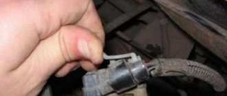
Disconnect one end of the wire from the spark plug.- Disconnect the second end of the wire from the ignition coil.
- Using a multimeter we measure the resistance of the wires.
- If the wire is in good condition, then the resistance on it will be in the range of 3.5-10 kOhm.
- We connect new wires to the spark plugs and coil. On the wire is the number of the cylinder to which it needs to be connected.
Signs of faulty armored wires of the VAZ 2114
The main signs of a malfunction of the VAZ 2114 armored wires are:
- Difficulty starting the engine;
- Unstable operation of the engine in idle mode;
- Increased hydrocarbon content in emissions;
- Radio interference, which can lead to malfunction of the multimedia system, electronic control unit and other devices
Therefore, in order to avoid lowering your ranking in search engines, a link to the source is required.
As a rule, when there is severe wear on the wire insulation, many microcracks appear, due to which current leakage occurs. As a result, the wire is not able to transmit to the spark plug a current that is sufficient in magnitude for its normal operation. This significantly increases the spark generation time and interferes with the correct operation of the engine cylinders.
Location of the ignition module of the old VAZ 2114
Quite often there are cases when wires are damaged as a result of contact with any engine elements. Situations of loss of cap tightness are also possible, and as a result - oxidation of contacts and current leakage. Regular cleaning of contacts is a mandatory procedure, especially when operating a vehicle in difficult climatic conditions.
Video on replacing the coil and high-voltage wires:
High-voltage ignition wires of the VAZ 2114 are part of the ignition system, through which an electrical impulse is transmitted from the module to the spark plugs. When the current hits the spark plugs, the fuel mixture ignites in the combustion cylinders, which gives rise to a new stroke of the engine.
BB wires must be of high quality
The design of the GDP, unlike conventional wires, is quite complex. In addition to the conductive core (which is made of copper) and protective insulation, they have metal tips and plastic protective caps.
Location of armored pipelines VAZ 2114 injector 8 valves
High-voltage wires in the VAZ 2114 are a mandatory part with the help of which a current pulse is transmitted to the spark plugs from the ignition module. The electricity supplied to the spark plugs causes the fuel inside the cylinders to ignite. This is what makes it possible to start a new stroke of the engine. When installing, it is important to follow the order of the armored wires in the VAZ 2114. The structure of such wires is special, because they consist of a fine-conducting copper core and insulation. At the end there are metal tips and plastic protective caps. It is very important to check their strength when purchasing. But, not only the quality of the conductors affects the operation of the car, but also the correctness of the connection.
WHICH GDP IS BETTER TO CHOOSE?
When choosing a GDP, two key factors must be taken into account - their resistance and breakdown voltage. The lower the resistance, the better the electrical impulse will be transmitted, and the magnitude of the maximum breakdown voltage determines how resistant the high-voltage wires on the VAZ 2114 will be to breakdowns.
The resistance value of products from different manufacturers differs from each other. As an example, we give you the resistance of the most popular types of GDP:
| Manufacturer | Resistance on cylinder No. 1 (kOhm) | Resistance on cylinder No. 2 | Resistance on cylinder No. 3 | Resistance on cylinder No. 4 | Breakdown voltage (kV) |
| Tesla | 3.27 | 4.16 | 5.02 | 6.26 | 50 |
| Cezar | 3.1 | 3.53 | 4.23 | 5.34 | 50 |
| Finwhale | 1.95 | 2.18 | 2.6 | 3.42 | 50 |
| Ween | 6.17 | 6.57 | 7.52 | 9.89 | 35 |
| Slon | 4.24 | 4.74 | 5.19 | 7.6 | 50 |
The products of the Czech company Tesla receive the largest number of positive reviews from the owners of the fourteenth. Their wires have optimal resistance and high breakdown voltage, and at the same time they are truly made to last - they do not tan or crack.
The cost of the Tesla GDP set is about 500 rubles, Cezar – 450 rubles, Ween – 270 rubles, Finwhale – 600 rubles, Slon – 500 rubles.
Briefly about the UMZ 4216 engine
The first experimental batches of engines of this class began to be produced in 2003. Ten years later, power plants began to comply with EURO-4 standards. Despite its age, the technical specification of the product is quite modern:
- Maximum potential – 106.8 hp.
- The total volume is 2.89 liters.
- Maximum thrust – 235.7 Nm. Achieved when the tachometer needle is in the range of 2,000-2,500 rpm.
The manufacturer provided an extended warranty. It was preserved even when HBO was installed on the car. In the basic version, the car uses 92-grade gasoline - this is the main type of fuel. The 95th is recognized as auxiliary - it also does not harm the engine.
- Aluminum block with 4 cast iron sleeves.
- Four-chamber cylinder head with 8 valves.
- ECU - MIKAS with sensors for camshaft, crankshaft, throttle assembly, detonation, absolute pressure.
CONNECTION FEATURES
The order of connecting high-voltage wires must be strictly sequential, since each cylinder of the engine corresponds to a specific socket on the ignition module. Considering that there is a numbering of the sockets on the ignition module body, the risk of confusing anything is minimal.
The procedure for connecting high-voltage wires of the VAZ 2114 injection type depends on the year of manufacture of your car. Fourteeners before 2004 had 4-pin ignition modules installed, and cars after 2004 had 3-pin coils.
The connection diagram for VAZ 2114 high-voltage wires to the ignition module (until 2004) is as follows:
Connection diagram for VAZ-2114 with ignition coils (after 2004):
In the pictures you can see the numbers of the landing slots. Each number must have a corresponding cylinder connected to it (cylinder numbering is counted from left to right).
To correctly install high-voltage wires on the VAZ 2114, follow the following algorithm of actions:
- Turn off the ignition. Open the hood and remove the power terminals from the battery;
- We remove the old GDPs from the mounting sockets on the module and cylinders;
- We remember the location of the high-voltage wires of the VAZ 2114 and connect new GDPs according to the diagram. Before replacing, it would not be amiss to draw this very diagram by hand on paper so as not to confuse anything;
- We connect power to the battery and, to check whether we did everything correctly, start the engine.
When installing the wiring, do not try to connect individual air intakes to each other with plastic clamps; to do this, you must use the comb holder that comes with them. A thin clamp can easily wear through the insulating coating. Also make sure that the GDP does not bend.
Connecting armored wires on VAZ 2115 and 2113 is carried out in a similar way.
HOW OFTEN SHOULD I CHANGE GDP?
According to the recommendations of Avto-VAZ, replacement of high-voltage wires of the VAZ 2114 should be done every 30 thousand kilometers. In practice, motorists rarely comply with these replacement deadlines, since if the wires do not have any mechanical damage, they can travel about 100-150 thousand km.
When the service life is exceeded, the internal resistance of the GDP increases, which negatively affects the transmission of the electrical impulse. This leads to problems with ignition and acceleration dynamics, since when the supply of current to the spark plugs is delayed, the normal engine operating cycle is disrupted.
Change the wires every 25-30 thousand km and everything will be fine
Briefly about the essence of how spark plugs work
A spark plug is an ignition element designed to create a spark that ignites the combustible mixture under the cylinder piston . Their number is determined by the number of cylinders in the internal combustion engine block.
Spark plug
They are a nickel body with a ceramic insulator, inside of which there is a contact rod. Their synchronous operation is achieved by replacing the entire set, that is, 4 pieces. It is advisable that they be of the same brand and manufacturer.