Print this article Font size 16
VAZ cars, which are classic models, are distinguished by pleasant reliability. This also applies to the steering mechanism.
It is quite complex, but its design allows you to maneuver and ensure reliable vehicle control even in the most difficult road conditions.
The modernization process led to the installation of a composite shaft and a safety column. Due to the size of the steering wheel, the driver makes the necessary maneuvers without any problems. From lock to lock, it takes 3.5 turns to turn the steering wheel completely. The force from the steering column is transmitted to the drive via a composite shaft.
The current steering mechanism on the VAZ 2107, a product of the Volga Automobile Company, is quite informative and does not allow the driver to get tired during long trips. There are certain difficulties when turning in a parking lot, but as soon as the car begins to move, the resistance weakens and turning the steering wheel becomes easier.
There is one more nuance - when the steering mechanism is working properly, there is a slight play. But its limit value complies with the traffic rules. This is due to the fact that there are steering rods on the VAZ 2107 and an impressive number of elements in the gearbox.
In general, the steering of the 7 can be considered reliable.
How to replace the steering gearbox on a VAZ 2104, VAZ 2105, VAZ 2107?
1) First of all, you will need to put the car on a viewing hole, or if you are not afraid, you can lift the front part of it with a jack and slip not very thick planks under the front wheels, and later lower the car onto them, in this regard, it will become even more above, but the work will not be very comfortable because, as they say, it’s up to you to decide what to choose.
Of course, if you put planks under the front wheels, we will tell you a couple of practical tips, and specifically, do not under any circumstances place bricks under the car so that it stands on them, since bricks (It seems that they are not strong) sometimes cannot stand loads in connection with this, they burst (In the best case) or break (In the worst case) and the car falls to the ground, in addition, it is recommended to slip something under the rear wheels so that the car will stop in place, and also for greater safety, raise the handbrake near the car and set it to speed so that it stands rigidly and does not roll anywhere!
Repair of the VAZ 2107 steering gear part 1
Replacing the steering gear
and shaft on my
VAZ
2104. It cannot be said that the old gearbox was already completely dead,...
The middle link is solid, has ball pins at the ends for connection with the pendulum arm and the steering bipod.
Each extreme rod consists of two threaded ends connected to each other by adjusting couplings. The adjusting couplings are fixed to the rods using two tie clamps.
Each of the rods has ball joints at the ends for connection with the steering axle arms, pendulum arm or steering bipod.
By rotating the couplings, the length of the side rods changes when adjusting the wheel toe.
Note. For cars produced since December 1971, the design of the steering axle levers has been changed: the surface of the lever in contact with the rubber protective cap of the ball joint, on the new levers, is lowered 17 mm below the axis of the hole for the lower bolt securing the lever to the steering axle. For levers of the previous design, the axis of the hole lies almost in the same plane with the indicated surface. In this regard, when replacing one of the levers of the old design with a new one on cars manufactured before December 1971, it is necessary to simultaneously replace the other lever.
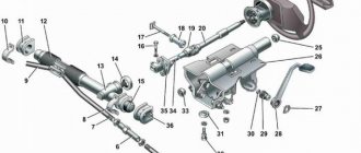
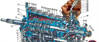
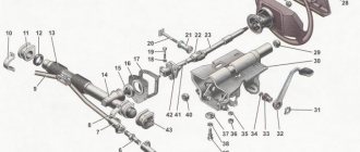
Rice. 1. Steering: 1 — steering mechanism; 2 — bolt securing the barter steering mechanism to the body; 3 — adjusting washer; 4 and 14 - flat washers; 5 - nut; 6 and 11 — spring washers; 7 — bolt for tightening the steering shaft on the worm shaft; 8 — shaft seal; 9 — bolt securing the rubber seal to the body; 10 — steering shaft; 12 — bolt securing the bracket to the body; 13 — steering shaft bracket; 15 — steering wheel; 16 — nut securing the wheel to the steering shaft
Rice. 2. Parts of the steering drive: 1 - right arm of the steering axle; 2 — bolt of the coupling clamp; 3 — outer right tip assembly; 4 and 11 — adjusting clutch clamp; 5 and 14 — spring washers; 6, 15, 31 — nuts; 7— clamp of the adjusting coupling; 8 — inner right tip; 9 — middle rod assembly; 10 — inner left tip; 12 — adjusting clutch; 13 — left steering axle lever; 16 — outer left tip assembly; 17 — adjusting clutch clamp; 18 — dirt cap; 19 — nut securing the rod end to the steering arm; 20 and 30 - cotter pins; 21 — bolt of the clamp; 22 — nut for fastening the pendulum arm; 23 - flat washer; 24 — axis of the pendulum lever; 25 and 28 — seals; 26 and 33 — bushings; 27 — bracket for the pendulum arm; 29, 35 and 36 - washers; 32 — upper washer; 34 — nut of the bracket fastening bolt; 37 — bracket fastening bolt; 38 – adjusting clutch; 39 — pendulum lever
—
The steering is used to ensure the vehicle moves in the direction specified by the driver. It consists of a steering mechanism and a steering gear. When a car turns, each wheel moves in its own circle. In order for the wheels to roll without slipping, it is necessary that the extensions of the axes of all wheels intersect at one point, which is called the center of rotation of the car. When turning, the outer front wheel describes an arc of a larger radius, and the inner one - a smaller one, therefore, it is necessary to turn the wheels at different angles. The inner wheel turns at a larger angle, and the outer wheel turns at a smaller angle. This is ensured by a steering linkage consisting of a front suspension beam, steering arms of the front wheel axles, a middle (long) and two short steering rods.
The steering mechanism serves to transmit and increase the force applied by the driver to the steering wheel to the steering gear. It consists of a steering shaft with a steering wheel and column, a crankcase, a globoidal worm with bearings and a double-ridge roller, which rotates on the axis of the steering bipod shaft head on a double-row angular contact ball or on needle bearings. The worm is mounted on two tapered roller or angular contact ball bearings located above and below the worm in the steering gear housing.
The steering gear transmits force from the steering mechanism to the steered wheels and is located behind the axle of the front wheels. It consists of a steering bipod pivotally connected to the middle rod, a pendulum lever, short rods and levers, and rotating struts of the front wheel axles. When you turn the steering wheel, the steering shaft, the worm and, through the roller, the steering bipod shaft turn along with it. The bipod moves the rod and through it the lever and rods, turning the left and right wheels.
Rice. 3. Steering mechanism: a - Moskvich car; b - VAZ; c — 3A3; 1 - worm; 2 — adjusting nut; 3, 4, 21— counter nuts; 5 — adjusting sleeve; 6 and 19 — oil filler plug; 7 — crankcase cover; 8 - roller; 9— roller axis; 10 — steering shaft; 11 — steering bipod shaft; 12 — oil seal; 13 — steering bipod; 14 — adjusting shims; 15— gasket of the adjusting screw; 16 — adjusting screw; 17—adjusting plug; 18 — lock nut; 20 — adjusting screw; 22 — coupling bolt. clamp; 23 - oil level inspection hole bolt
Rice. 4. Steering gear: a - diagram of the Moskvich steering gear: 1 - left steering column lever; 2 — outer tip of the left short rod; 3 — adjusting coupling; 4 - left and right short rods; 5 — steering bipod; 6 — average thrust; 7 — pendulum lever; 8—lock nut with left-hand thread; 9 — lock nut with right-hand thread; 10 — outer tip of the short tie rod; 11 — right arm of the axle pivot strut; 12— rotary stand; b — ZAZ steering gear diagram: 13 — middle thrust locknut with right-hand thread; 14 — lock nut with left-hand thread; 15 — average thrust; 16 — pendulum lever; 17 — hole for turning the rod with a crank; 18 — steering bipod; 19 — steering axle lever; 20 - short thrust; 21 — turn limiters
—
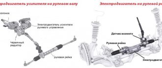
In front-wheel drive vehicles, more load is placed on the front wheels, which requires more effort to turn them. Therefore, such cars use steering mechanisms with a large gear ratio and a higher efficiency.
Vehicles are equipped with a safety steering system with a rack and pinion steering mechanism. This type of steering is compact and simple in design, more technologically advanced in manufacturing and goes well with the front-wheel drive layout of the car and the transverse arrangement of the power unit. In order to increase passive safety, the steering wheel has a damping element.
The steering system consists of a steering gear and a steering gear.
The steering mechanism assembly with steering rods is attached with two brackets to the front panel of the body. To dampen vibrations, rubber cushions are installed between the crankcase and the panel, as well as on both crankcase supports.
The crankcase (of the eul mechanism is cast from aluminum alloy together with the left support. A drive gear is installed in the cavity of the crankcase on ball and roller bearings. The ball bearing on the gear shaft is fixed with a retaining ring. The outer ring of the bearing is pressed against the end of the crankcase socket by a nut, in the recess of which an O-ring is installed with a protective washer. The nut is locked in the crankcase with a washer and covered with a boot, which is mounted on the drive gear shaft. Marks A and B are made on the steering gear housing and on the boot for proper assembly of the steering mechanism.
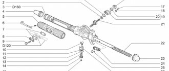
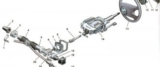
Rice. 5. Steering assembly: 1 — tie rod end; 2 — ball joint of the tip; 3 — rotary lever; 4 - nut; 5 — adjusting rod; 6 — left tie rod; 7 — bolts securing the steering rods to the rack; 8 — right steering rod; 9 — bracket for fastening the steering mechanism; 10 steering gear support; 11 — protective cover; 12 — connecting plate; 13 — locking plate; 14 — rubber-metal hinge; 15 - sealing ring; 16 — rack support sleeve; 17 — rack; 18 — steering gear housing; 19 — coupling coupling bolt; 20 - plastic coupling; 21 — upper part of the facing casing; 22 - damper; 23 steering wheel; 24 - ball bearing; 25 — steering shaft; 26 lower part of the facing casing; 27— steering shaft mounting bracket; 28 — protective cap; 29 — roller bearing; 30—drive gear; ball bearing; 32 — retaining ring; 33 — protective washer; 34 - sealing ring; 35 — bearing nut; 36 boot; 37 — sealing ring of the stop; 38 — retaining ring of the stop nut; 39 — rack stop; 40 - spring; 41 — stop nut; 42 — ball joint pin; 43 — protective cap; 44 — ball pin insert; A - mark on the steering gear housing; In the mark on the boot
The gear is in mesh with a rack, which is pressed against the gear by a spring through a metal-ceramic stop. This stop is sealed in the crankcase with a rubber ring. The spring is pressed by a nut with a locking ring that prevents the nut from being unscrewed. Due to the spring-loaded stop, backlash-free engagement of the gear with the rack is ensured over the entire stroke of the latter. The rack rests on the stop at one end, and on the split plastic sleeve at the other. There are grooves on the outer surface of the bushing into which rubber sealing rings are installed. The rack bushing has three protrusions that fit into the sockets of the steering mechanism housing when installing it, thereby protecting the bushing from axial displacement and from turning.
A protective cap is put on the steering gear housing on the left side, and a pipe with a longitudinal groove is pressed onto the right side. The bolts that secure the steering rods to the rack pass through the groove of the pipe and the holes in the protective cover. The bolts are connected to each other by a plate. Both bolts pass through rubber-metal hinges pressed into the heads of the rod ends. The bolts are secured with a locking plate.
The travel of the rack is limited on one side by a ring pressed onto the rack, and on the other by the bushing of the rubber-metal rod joint. In this case, both the ring and the bushing rest against the steering mechanism housing. The cavity of the steering gear housing is protected from contamination by a corrugated cover, which is secured with two plastic clamps, as well as a protective cap.
The steering shaft is connected to the drive gear by an elastic coupling. The upper part of the shaft rests on a radial ball bearing with a plastic sleeve, which is pressed into the bracket pipe. At the upper end of the shaft, the steering wheel is secured with a nut on splines through a damping element.
The steering shaft mounting bracket is attached at four points to the body bracket. A connector for the steering column switch is mounted on the bracket pipe, and the contact part of the sound signal is attached to the lower end of the damping element. The steering column switch and the horn switch are covered with a protective casing consisting of upper and lower parts connected with screws.
The steering drive consists of two horizontal rods and rotary arms of telescopic front suspension struts. Composite rods. When adjusting the toe-in of the front wheels, the length of each rod is changed by a tubular rod, which is screwed onto the rod ends and secured with nuts.
The head of the outer tip contains parts of a ball joint, consisting of an insert and a ball pin, a spring and a protective cap. The plastic liner, together with the pin, is constantly pressed by a spiral spring against the conical surface of the tip bore. Due to the presence of a longitudinal cut in the liner, the gap between the liner and the finger is automatically selected.
The other end of the spring rests against a plug rolled into the tip. The joint cavity is sealed with a protective cap, which at one end fits into the bore of the tip, and the other is tightly fitted onto the finger.
The swing arm is welded to the front suspension strut housing. A bushing with a conical hole for the ball joint pin is mounted into it.
The steering mechanism parts are lubricated with Fiol-1 lubricant, which is placed in the mechanism housing and on the parts during assembly of the mechanism, and the ball joint parts are lubricated with ShRB-4 lubricant, also during assembly. During the operation of the vehicle, the steering parts are not additionally lubricated, except in cases of damage to the protective covers and caps, when it is necessary to disassemble the steering control and replace the lubricant, caps, covers, and possibly other damaged parts. All these operations should be performed at a service station.
Steering Maintenance
After the first 2,000 km, and then every 15,000 km, it is necessary to check the condition of the steering rod ball joints, protective rubber covers and caps, and the free play of the steering wheel.
Checking the condition of the steering should be carried out by two people, on an overpass or inspection ditch. First of all, you need to make sure that the steering wheel spoke is horizontal with the wheels in a straight position. If the spoke deviates from the horizontal, it is necessary to determine the cause of the malfunction and eliminate it. Basically, this malfunction occurs due to improper assembly of the steering mechanism and to eliminate it, you must contact a service station.
By turning the steering wheel from lock to lock, you need to check by inspection and by ear: - the reliability of the fastening of the steering mechanism and the steering wheel; — no play in rubber-metal joints and ball joints of steering rods; — reliability of tightening and locking the bolts securing the rods to the rack and the nuts of the ball joint pins; — no jamming or interference that prevents the steering wheel from turning.
Loose connections must be tightened.
If knocking and jamming is detected, it is necessary to disconnect the rods from the rotary arms of the telescopic suspension struts and repeat the check. After making sure that the knocking and jamming comes from the steering control, you need to remove it from the car and replace it with a new one or have it repaired at a service station.
Rubber-metal hinges must be replaced if the rubber bushings have bulging, ruptures or free play (play) in the hinges.
If the protective cap of the steering rod ball joint has cracks, the cap must be replaced, first adding ShRB-4 lubricant to it. The cap must also be changed if, when squeezing it with your hands, the lubricant comes out.
You should make sure that the protective cover is securely fastened and that it is sealed. When turning the steering wheel, you need to check whether the protective cover has any bulges or pinches. Otherwise, it is necessary to determine the cause of the malfunction and eliminate it.
Basic steering malfunctions and ways to eliminate them
The procedure for identifying and eliminating some faults is discussed in the “Steering Maintenance” section.
Increased free play of the steering wheel. Causes of the malfunction and ways to eliminate it: - loosening of the nut securing the ball pins of the steering rods. Check and tighten the nuts; — increased clearance in the ball joints of the rods. Replace the rod ends; — wear of rubber-metal joints of rods. Replace rubber-metal hinges or rods; — loosening the rack stop nut. Adjust the steering mechanism at a service station and replace damaged parts; — wear of the bushings of the elastic coupling of the steering shaft. Replace flexible coupling.
Noise (knocking) in the steering. Causes of the malfunction and ways to eliminate it: - loosening of the nuts of the ball joints of the rods. Check and tighten the nuts; — loosening the rack stop nut. Adjust the steering mechanism at a service station and replace damaged parts; — loosening of the steering mechanism. Tighten the fastening nuts; — loosening the bolt securing the lower flange of the elastic coupling to the gear shaft. Tighten the flange bolt.
Stiff rotation of the steering wheel. Causes of the malfunction and ways to eliminate it: - damage to the bearing of the upper support of the suspension strut. Replace the bearing or support assembly; — damage to the support sleeve or rack stop. Replace damaged parts and apply lubricant. It is recommended to perform these operations at a service station; — low pressure in the tires of the front wheels. Set tire pressure to normal; — damage to ball joint parts. Replace damaged parts; — damage to parts of the telescopic stand. Replace or repair the suspension strut.
Adjusting the steering column play
The need for adjustment occurs after the unit has been restored or when there is a large gap when twisting the steering wheel. If there is a large gap in the mechanism, the wheels remain slightly behind the steering wheel. To adjust you will need:
- flat screwdriver;
- Key 19 mm.
We issue a movement to the center, then we do the following:
- Using a 19mm flat key, unscrew the nut on the top of the steering gear.
Video: adjusting the steering column play on a “classic”
Removing the gearbox
The design of the gearbox does not allow it to be repaired without removing it from the vehicle. In order to remove it, you must:
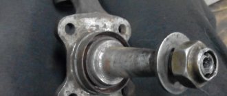
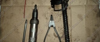
- Disconnect the tie rod ends from the gearbox. First, they are uncoiled, then the nuts are unscrewed with a 22 wrench and the tips are pressed out using a special puller.
- Unscrew the clamp securing the steering shaft to the gearbox.
- Remove the three bolts that secure the gearbox to the car body.
The gearbox design should not cause any particular difficulties when repairing it. You just have to take into account that the worn elements, called the worm pair, are both replaced at the same time. After this, adjustments must be made.