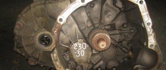
It started with the fact that I got tired of changing the crosspieces, injecting the splines of the cardan shafts, which I then replaced with new ones, and the splines on them were also covered with entrails. I went to 10 workshops to get the RK installed correctly - nothing worked. The hum and ringing of the RK jumping all over the body led me to the FAQ. After reading a lot of smart articles on hanging the RK, I started doing it myself. Result - I drove for 2 months with slightly reduced vibration, and then bang - the intermediate cardan (if that's the correct name) was ruined. I climbed again myself. I removed the gearbox and gearbox and found: Boiled bottom (tear off the master’s hands), half of the bottom is flat (not boiled), the other is at an angle of 60 degrees. And rotten places where the gearbox is attached:
As a result, I went back to the Internet and here is my salvation: Transfer case subframe - but it seemed heavy and difficult to manufacture (you need to look for such a channel), and I didn’t want to drill through the bottom. And the clearance is decreasing, as I understand it’s not bad. But there was a huge plus - there were drawings.
The last 3 were more to my liking, and I, taking a caliper and a tape measure, crawled under my old lady, guided by what I have from the drawings at the last link, which was included in the basis, and the dimensions from the book on Nivka, but also with my own modifications .
You definitely need to measure it on your car.
So, I drew sketches and, based on them, first made a model from wooden beams and plywood, then I corrected the drawings and only after that I sent them to production:
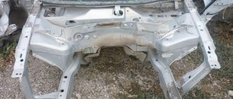
I gave it to a local factory, and they welded me something like this from their material, according to my drawings:
I wore it back and forth 2 times - for fitting (the main thing is that the suit fits):
The height of the structure is slightly less than https://vaz2120.h1.ru/popov/popov.html, which has a positive effect on ground clearance.
ATTENTION. ATTENTION. ATTENTION. ATTENTION.
1) These drawings were developed taking into account the use of a square pipe - 60x30. During the work, it was decided to replace the material with a 40x25 square pipe (this strength is more than enough), while maintaining the axial dimensions. Unfortunately, there is no time to redraw. But at the factory they understood everything anyway.
2) I didn’t turn the bushings into the side members (labor-intensive), but for strength, so as not to squeeze the side member? I placed a plate on its outer side along the length of the subframe, which distributes the load over the entire length, and not pointwise.
Yes, by the way, the project budget was about 600 rubles: 500 rubles. - at the nth plant they welded the entire structure for me, from their material and 100 rubles. for bolts, nuts, etc.
Update dated 05/08/07, by vvv.
The subframe is made of a 60x30 rectangular pipe and 50x50 corners without welding. Everything is bolted on. Fastened with through vertical M12 bolts through the spar. In the interior, under the bolt heads, there are 100x100 mm washers, about 5 mm thick. The design has been on the car for 3 years. The flight is normal.
do-it-yourself stretcher on the field photo
There are also some disadvantages, but they are not significant. The ground clearance is reduced, and if you make it yourself, this is quite labor-intensive work.
Of course, you can purchase a ready-made subframe, but there are ways to make your own.
The transfer case subframe is made using a sheet of metal, a channel and corners. Download the exact manufacturing diagrams to make all measurements using them. At construction markets you can purchase everything you need.
The connection of the nodes is bolted. To connect the subframe to the field you will need:
– 4 bolts size M12*1.5;
– 4 bolts size 12*1.25.
To work, you need to prepare all the necessary tools. It is best, of course, to do everything on a milling machine. But if this is not possible, then prepare, first of all, personal protective equipment for your hands and face. Next, prepare an angle ruler, a roll, an ink, a hammer, a caliper, a drill with the highest possible power and a small and large grinder.
First of all, we measure all the distances from the base edge of the channel and process it. The thickness of the sidewall wall at the junction with the top flange is 8 mm, so when cutting in the transverse direction, the length of the cut should end at the same distance to the edge of the upper flange of the channel. Transverse windows should be cut out with a small grinder. And the longitudinal ones are big. Once you've cut the windows, you need to chamfer them, but before you do that, you also need to cut out the outline of the side.
Frame for Niva in detail. 1. — Lada 4×4 3D, 3.0 l., 1993 on DRIVE2
How to make a snowmobile track with your own hands from a tire
Hi all!
With God's help and such and such a mother, today I started making a frame for my zombie field. I wrote about the reasons for such serious “tuning” earlier in my logbook.
Having studied the drawings, I did not put off the matter. In the morning I went to the metal depot and bought 12 linear meters of 80x60 mm profile pipe. By lunchtime the metal was at my house.
Full size
Metal has arrived
Next, I built something like a welding table from scrap materials. To do this, I used two wooden stools that I made a long time ago and are used in all occasions in life :))) On them I placed an I-beam 200mm wide. I checked the plane using the rule. I also put a flat chipboard slab on top, 4 cm thick. I checked the plane again, everything is level. I’m not interested in horizontality yet, I’m interested in a flat plane on which I can weld the parts together.
Full size
Improvised welding table
Full size
Tormenting the drawings
I cut several frame parts and assembled them with tacks. I measure everything 20 times, it converges to 1 mm. I cut the profile with a small turbine, I don’t have another. So that the disc does not move away and the cut is smooth, I use a clamp for pieces of wood and a piece of channel with a flat side. A piece of channel serves as a kind of ruler-stop; I move the disk along it.
Full size
This is how I cut my profile
I tested my homemade sandblasting machine, I’ll post a detailed report on it later. I'm happy with the preliminary result, I saw some mistakes, I'll fix them tomorrow.
Full size
Sandblasting test
Full size
More sandblasting
To be continued, good mood everyone!
www.drive2.ru
Subframe drawings for Niva photo
Between the mounting holes, the mounting angles to the cross member and spar can be of free sizes in length and distance. It is necessary to observe the size of the height of the attachment to the subframe, and, by the way, you can use the attachment to the spar of other schemes instead of the corners. You can make two types of dispensers. Basic type and reinforced. In the reinforced version, the ends of the channel are tucked under the fastenings of the transfer case brackets. Also in the reinforced version, the oblong holes for attaching the transfer case brackets are repeated.
The type of connection of the subframe protection is bolted, and is attached at the bottom to the corners. But at the same time, the holes must be threaded in the lower flange of the corners and in the body of the sidewalls of the subframe. To impart strength, sheet protection is used; it forms the part of the structure that forms the box. In order to be able to drain oil, water and trapped dirt, it is necessary to make several holes under the drain plug and between the sidewalls of the channel in any convenient place. To increase protection, it is necessary to attach the corners to the frontal part of the subframe and to the support mount for the box itself. If the subframe is not protected, this may lead to its deformation, as head-on collisions with possible obstacles and tree stumps are possible.
Subframe for transfer case, gearbox
2 I decided to install a subframe 3 I decided to install it, and the support for the gearbox is also on the subframe 4 Dimensions are only in fact for your field!!! after some measurements according to the drawings, these will not fit or will require modification 5 Places the transfer case on “soft” Shniv pillows! 6 transfer case Never use 3 supports! Questions have arisen!!! 1 is it worth putting a subframe on the pillows (between the subframe and the longe)? 2 Should I put bushings in the saddles or not? 3. Vertical or horizontal mounting of the spar? —— ——I’ll try to explain it as a beginner and not burdened by the dogmas of the old Nivavovodov 3. It’s quite reasonable and practically, when making the subframe, it’s not a problem to add ears for attaching the subframe to the gearbox support. IMHO it’s best not to remove the cross-beam of the rear gearbox mounting - this is an additional support for the gearbox when shooting for repairs of the transmission along with the subframe - there is no need to support the gearbox - when you remove the subframe, the gearbox will remain in place. The traverse holding onto the bottom and at the same time connected to the subframe gives greater rigidity to the subframe mount, including in the mount of the subframe and the place where the traverse is attached. 4 is correct, you need to adjust it to the location, but the guidelines for procuring materials can be taken from the dimensions of the drawings with a margin tolerance of 5 - I don’t know this, although soft pillows have a minus - they shift the rk more during the reaction torque from the cardans (that’s why 3- I am a support so that it does not protrude from the washout unit, which in this case works for lateral shift, keeping the yoke from the desire to turn, which is then prevented (smoothly) (rubber suspensions. 6. The 3rd support, in addition to compensating for the force from the reaction torque of the cardans, does not allow the yoke to peck corners along the axis of movement, again freeing the shaft assembly from the displacement load (now in a different plane).
1. why more pillows? The task of the regular two is to compensate for the reactive moments on the rk and dampen its vibrations. The range of operation of standard suspensions covers the range of vibrations caused by the system of gear wheels. If you also hang the subframe on the cushions, the displacement of rk during reactive moments will increase additionally by the free play of the subframe suspensions (after all, there is already free play in the range of standard suspensions). obtaining that the PK will be, as it were, not fixed at all, having double free play (travel of the standard suspensions plus the travel of the subframe suspensions. In practice, the total travel will be less due to some mass of the subframe, but still more than with standard suspensions and a fixed subframe) 2. bushings in the dungeons - of course it’s better with them, although I made do with a fastening area of 6x5.5 x 0.4 cm and washers of the same area on the other side of the spar (horizontal drilling) the bushings will not allow the spar to be compressed and deformed, but I have three attachment points on each side, I don’t squeeze fanatically) 3. horizontal drilling makes it easy to remove the subframe together with the subframe, which is more difficult with vertical bolts (to inspect the subframe, you need to remove it with the subframe, so as not to disturb the alignment of the subframe, which is set and tested, because the subframe will again become practically exactly in the old place because of its fastenings) you can weld bolts or nuts on the bottom-floor from the interior side, then the issue of removing the subframe with vertical drilling for the bolts is simplified. but when drilling vertically, it is necessary to immediately provide for the mounting location of the subframe, taking into account the subsequent placement of the bolts in the right places on the floor of the cabin, and there it is not possible to conveniently fasten either the bolt head or the nut everywhere, and a place for the washer must be provided
Factory design
One of the recommended devices for eliminating transfer case vibration is the so-called “Niva Comfort” kit. The Niva Comfort subframe was developed a relatively long time ago, has a quality certificate, and Niva 2121 owners often use it.
This device is a welded structure made of metal corners, with drilled fastening points, mounting plates to which the base will be mounted. Since the transfer case should not be fixed rigidly to the base, the kit includes elastic supports.
For all its advantages, this subframe for the transfer case has disadvantages. It is installed in the places where the box was previously attached, that is, to the bottom, so if there are problems with the base, installing the Niva Comfort design will be problematic.
Installation of subframe step by step video
Video 2 off-road rides
For what? You ask. I will answer - to reduce noise, resonance and vibration, and in the end - to protect the Niva 2131 transfer case itself. In the serial Niva, the transfer case supports are attached directly to the floor, which accelerates fatigue damage to the body. There are often cases when, in the fifth or seventh year of operation, the floor in the places where the supports are attached collapses and rots through. However, it is possible to reduce the effect of vibrations on the body by integrating the unit into the power component of the body. In addition, in the places where the transfer case is attached, the floor will be unloaded - due to this, it will rot and collapse less. Regardless of the driving mode, the gearbox and transfer case control levers do not dance, and the level of vibration and noise is close to that of a classic Zhiguli. The transfer case supports are installed in such a way as to ensure a minimum moment of inertia during its oscillations and a maximum resistance to movement due to bending moments.
The subframe for the VAZ 2121 not only increases the load-bearing capacity of the body, but also protects the transfer case from below. At the same time, the ground clearance remains the same, only the ramp angle has changed slightly.
- The subframe for alternative mounting of the Niva 2121 transfer case has a number of advantages:
- monolithic frame;
- reduces all kinds of vibrations and noise to a minimum;
- unloads the floor;
- increases the possibilities of adjustment along the axes;
- is a natural protection for the transfer case.
Homemade design
Many people make a similar subframe for the Niva on their own. First you need to make a drawing of the subframe. The simplest design consists of two crossbars and two crossbars connecting them.
The distance between the crossbars should be exactly the same as the distance between the transfer case attachment points to the bottom. Holes are made in the crossbars themselves to which the transfer case will be attached. To strengthen the structure, you can weld braces from metal corners in the inner corners between the crossbars and crossbars.
This design will be attached not to the bottom, but to the side members, so their length must correspond to the distance between the side members. Having made a drawing, you can create this device on the Niva with your own hands. Depending on the wishes of the owner, it can be made collapsible, bolted.
The advantage of such a subframe is the ability to replace a damaged element without removing the entire structure from the car. The disadvantage will be the need to constantly monitor the condition of the bolted connection. The welded structure of the subframe does not require constant monitoring, but if damaged, it will have to be completely replaced.
Next, you need to decide how the subframe under the transfer case will be attached to the side members. It is possible to attach it to the side surface of the subframe. To do this, you will need to drill through holes in the side surface at the mounting points.
The advantage of fixing it to the side surface of the spar is the ability to additionally install silent blocks at the fastening points, which will further dampen vibrations coming from the transfer case. The downside is the need to carry out additional calculations of the diameter of the bolts with which the structure will be attached to the spar, since in this case they will be subject to shear force. A bolt with a diameter that is too small will likely fail quickly due to vibration.
Materials, tools and drawings
The protection is mainly used for models 21214, 2121, 21213, which have vibration problems. To assemble a subframe on the field with your own hands for a transfer case, you will need metal channels, angles, bolts and a sheet of thin metal as the main materials. In addition to the materials, you need to get diagrams or a drawing of the subframe. The simplest design consists of two transverse parts and two crossbars that connect them. The tools you should prepare are:
- grinder;
- drill;
- measuring instruments - calipers, ruler;
- bank;
- hammer.
To protect against metal filings, you should take protective clothing made of thick fabric.
There are several design options, so the number of channels and angles may vary depending on the drawing.
Other device mounting options
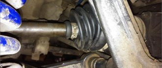
Installed part on the machine
Another way to secure the structure to the spar involves fixing it to the lower surface of the spar. For this purpose, holes are also made in the fastening points, but only in the upper and lower surfaces of the spar. In this case, you should not particularly find fault with the diameter of the fastening bolt, since there will be no impact on it. But it will be impossible to install additional silent blocks to dampen vibrations.
Another additional element that can be installed on the structure is a special elastic support for the box. It is believed that it allows you to better set the position of the box relative to the gearbox. But in some cases they can do without it. It all depends on the wishes of the owner.
Some car enthusiasts cover this entire structure with a sheet of metal, which additionally protects the transfer case from contamination and possible damage when driving off-road.
The disadvantage of the subframe installed on the Niva is the reduction in ground clearance in the transfer case area.
Installation
For ease of installation, the car is fixed on a lift or above a pit. Pre-preservation of surfaces (attachment points, subframe) is carried out using protective agents, for example, Movil.
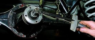
The finished product is tried on site individually for each vehicle. 4 holes are drilled along the perimeter of the structure, symmetrical relative to the center line. Having previously loosened the transfer case fasteners.
Having placed the plates on the interior side, as in the photo, the subframe is attached to the side members with M12x1.25 bolts.
The RK brackets are sequentially removed, turned over and freely fixed to the subframe. The position of the shaft flanges is adjusted until minimal gaps are formed by moving the entire structure. Alignment is performed at 3000 rpm with the machine standing.
The bolts are thoroughly tightened.
Tuning VAZ-2131. Fighting vibration
We radically combat congenital design flaws
So, if you remember, last time we stopped at the fact that the Niva was shaking. Everyone knows this, even those who have never driven it. It shakes at different speeds and with different intensities. It used to shake more, now it shakes less. On our test subject, the peak of vibrations occurred in, perhaps, the most unpleasant range of 90–110 km/h. Before and after, the transfer case handles usually shake, the floor vibrates, but this does not affect the lower back. After 90, a noticeable resonance begins, reaching a peak at 100 km/h and disappearing at 120. And although I don’t mind driving 120 km/h where it’s not prohibited, don’t forget that we’re talking about a Niva. Internet deadpools have these cars easily accelerating up to 170 km/h, but I understand that 130 is already the ceiling. Oil is consumed in liters, fluids flow in waterfalls, bearings wear down, and gearboxes wear out. The most comfortable speed on the highway is 100–105 km/h. After modernization in 2009, the Nivas became surprisingly stable, and the long wheelbase stabilizes them so much that you can easily throw the steering wheel at 120 km/h and the car will not veer off course even a degree. In general, as you understand, only vibration interfered with a good ride.
I once had a 2006 Chevrolet Niva. She shook noticeably at 60 and 90 km/h. I changed the cardans, centered something, adjusted, tightened and injected. The result most often was the loss of reverse gear. Or the first, it’s how they’ll regulate it... In a word, I still haven’t solved the problem, but just then a buyer turned up. I decided to rid the current Niva of vibrations in a radical way - by placing the transfer case on a subframe. I know, not everyone likes them, but, you see, the remedy is actually radical.
As it turned out, the market near Moscow now sells about five different products, both from local craftsmen and those who came from afar. The principle is approximately the same for everyone - the transfer case is torn off from the bottom and placed on a certain frame-like structure, which is then screwed to the amplifiers. The reviews for all subframes are approximately the same: “It seems like the shaking has become less, but not particularly…” This is what they say about all but one. A small workshop under the promising sign “Comfortable Niva” makes a device that they say admiringly, they say, there are zero vibrations, the design is super. I must admit, I was surprised by such unanimity in the reviews, and I decided to try this miracle unit. And this is what came out of it.