The function of the solenoid is as follows: when we engage reverse gear and drive backward, the contact in it closes and the reverse lights come on, and a buzzer sounds in the cabin. However, sometimes it happens that we have turned off the reverse gear, are driving forward, but the buzzer continues to emit a signal and the reverse lights do not go out. In this case, it is necessary to replace the reverse gear solenoid . The opposite may happen: reverse gear is engaged, but the buzzer does not emit a sound signal and the lights do not turn on. In this case, you need to inspect the wiring near the solenoid connector. The reason may be rotten and torn wiring - it needs to be repaired.
In order to replace the reverse gear solenoid , jack up the front left wheel or lift the car on a lift. Remove the front left wheel. Remove the left side of the engine protection from the bottom of the car.
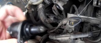
Then remove the electrical connectors from the solenoid. And from the speed sensor.
Using key No. 36, press the solenoid. And manually unscrew it from the gearbox.
We take a new solenoid and screw it into the transmission block.
Thanks for subscribing!
We clamp it. We put electrical connectors on the solenoid and speed sensor. Now you can check how it works. Turn on the ignition (do not start the car).
We turn on reverse gear, the buzzer and reversing lights work, turn it off and they stop. We assemble the car, install the wheel.
For stable engine idle operation, the Kalina idle speed sensor is designed. In this article we will talk about the Lada Kalina - about the characteristic features of the device on this car, what problems may arise and how to fix them, and recommendations for replacing the device will also be given.
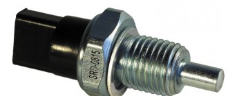
Reverse sensor
Characteristics of the XX controller
Let's take a closer look at the XX sensor.
Purpose and principle of operation
The idle speed sensor is an electric motor with a conical needle of a certain thickness. This device is located on the throttle body next to the throttle position device, and is secured with two screws or using technical varnish.
The device has a single purpose: to stabilize the engine idle speed, and everything happens this way:
- When the engine is idling, a certain volume of air enters, which allows it to operate normally.
- The device does not read or control anything, it does what the ECU tells it to do. The unit controls, reads and, according to the tachometer readings, gives a command to the XX regulator.
- If you warm up the car engine to the optimal temperature, the controller will maintain speed. If it is not warmed up, then due to the operation of the IAC controller, the speed will increase. This manipulation will ensure the optimal engine temperature at higher speeds by analyzing the operation (author - RussianTuning).
Typical faults
Like any systematically operating device, the DXH may experience various problems, for example:
- The car suddenly stalls while idling.
- The DXX turnover is not systematic and “floats”.
- When starting the engine without preheating, the controller does not start working and the sensor does not rotate as it should.
- It suddenly stalls when changing gear on the gearbox.
- The DHW speed hangs after releasing the pedal or when activating various automotive equipment.
When all these strange things happen to a car, it is obvious that the problem lies with the regulator. Unfortunately, this device does not have self-diagnosis, so to figure out what exactly is the cause of the malfunction, you need to check it yourself. And if it can’t be fixed, then replace it. Replacing the idle speed sensor on Kalina will be covered below.
Also check out
- Fuse F21 is a 10A fuse in the fuse block, 8th from the left. Take it out and check it with a tester. If it is defective, replace it with a new one.
- Check the switch by lifting the cover on the handle. This will free up access to the connector connected to the switch. Disable it carefully.
- Using a paper clip, we close the contacts of the connector from which the wires are lowered under the floor of the car. Try to engage reverse gear. If this works, the switch is broken.
- Disconnect the connector from the solenoid and install 2 pins into it. Use a tester to change the voltage. The device readings should be 12 Volts. It is worth charging it with a light bulb (5 Watt or 12 Watt). If it does not light up, then there is an open circuit, and the voltage arises due to resistance formed due to copper oxide. Very often, breaks and fractures occur on the harness in the place where the clamp is located on the pallet.
- Remove the clamp by pressing its fastenings at the bottom.
- Disconnect the connector from the stop switch and remove the harness. Remove the electrical tape from the corrugation, after which you can remove the wires. In the event of a break or breakage, characteristic signs will be noticeable.
- Use wire cutters to disconnect the wires and connect them of similar cross-section and diameter. The twist should be soldered and insulated (you can use heat shrink). If necessary, put on a new corrugation. This is done so that moisture does not penetrate inside, otherwise it is possible that all the troubles will happen again. The harness should be secured with a plastic clamp.
- Connect the connectors and check the operation of the solenoid. Failure of this element is quite rare. To check it you need to connect a tester. The resistance should be 2.2 Ohm. If the cause of the malfunction lies there, you will need to drain the oil from the box. One option is to quickly block the hole with something and install a new solenoid. In this case, it is important to apply sealant to the threads so that oil does not ooze down the threads during operation.
Characteristics of the 3X sensor
Let's figure out what the 3X controller is!
Purpose and principle of operation
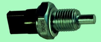
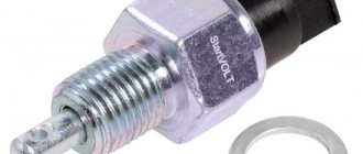
The reverse sensor on the Lada Kalina is located on the gearbox. The purpose of this device is to ensure that the rear lights turn off immediately when you stop reversing. The above-mentioned gearbox has a special coil installed that blocks reverse gear if problems arise with the sensor.
There is a ring on the gearbox lever with which reverse gear is given. As soon as this special part is lifted, a current charge is given to the coil, which draws in the coil core. These actions free up space for changing reverse gear. This pulse also signals the reversing indicators to turn on. If the headlights are turned off, the opposite situation is created when the core falls into place.
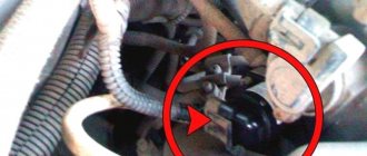
Location of the reverse gear
Typical faults
Lada Kalina is not a bad car, but there is one feature in it that completely spoils many of its advantages. This feature concerns the inclusion of reverse gear. The wiring on the gearbox is so thin and vulnerable that they can break at any moment if you do not handle them carefully.
There are other common problems:
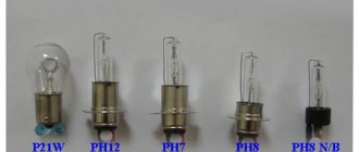
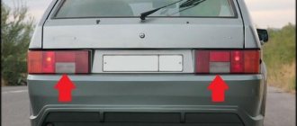
- When you can reverse, but the light does not light up. If we are talking about one lamp, then the problem is with it and it will need to be replaced, if both do not light, you need to examine the circuit between the part and the lamps.
- Reverse indexing chain problem. In this case, you need to diagnose the ring on the gearbox.
- Often work stops due to the wires that lead from the sensor to the bottom of the machine, where the wire is affected by the environment and the contact can easily oxidize.
Reasons for the loss of reverse gear on the VAZ 1118
Idle speed sensor Lada Granta 8 valve
You need to lift the cover.
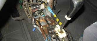
The wiring running from the gearshift lever to the solenoid is located on the Lada Kalina near the left side member under the bottom. Because of this, it is affected by water, snow, and reagents from the roads also affect its condition.
Long-term use of the car leads to rotting of the wire. The presence of voltage at the solenoid output is checked. If it is, then the wiring is broken, you need to inspect it for damage.
After the previous check, there may be a different result - there will be no voltage at the output. If the fuse is intact, it remains to ensure the integrity of the winding inside the solenoid.
For diagnostics, all wires are disconnected from the element and the voltage on them is checked. If so, the solenoid has burned out. Otherwise, the problem lies in the power supply in the area from the fuse to the lever.
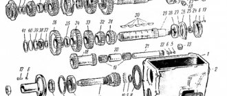
To find out why there may be no reverse gear on a VAZ car, you need to understand what kind of design it is, what parts and assemblies it consists of. The reverse gears themselves are located inside the gearbox, in the housing, just like the speed selection mechanism, located outside the crankcase:
- two scenes (jet thrust);
- shift lever (RP);
- solenoid blocking the gearbox, screwed into the gearbox housing from the outside;
- locking ring located on the lever rod;
- switch located in the gearshift knob.
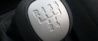
The reverse gear lock (RP) protects the gearbox from accidental engagement, and to engage the RG, you need to lift the locking ring up, first move the lever all the way to the left, and then move it forward. But sometimes it happens that even with the switch raised, the ZP refuses to work; the RP stubbornly refuses to take the desired position.
So, why doesn't reverse gear engage:
- there are defects on the gears of the gearbox;
- there is no normal clutch release;
- the spring on the axis in the speed selection mechanism broke;
- solenoid does not work;
- The sensor contacts do not close;
- there was a break in the wire supplying power to the blocker;
- fuse F21, responsible for the operation of the blocking device, has burned out.
The gearbox may not yet turn on if the link (thrust) is not adjusted, but in this case problems will also arise when trying to turn on some other speed (for example, first or fifth). That is why, whenever removing a manual transmission, it is recommended to put marks on the slide so that during reassembly it can be installed in exactly the same position.
Another reason for the malfunction of the gearbox is an unadjusted or poor clutch, but here, too, other gears either do not engage or shift with a crunch. The travel of the clutch pedal on Kalina is adjusted by decreasing or increasing the length of the cable; when the disc is worn out, the car begins to drive with slipping and does not pick up speed well.
Reverse Controller Replacement Guide
To make a replacement, even an ordinary car enthusiast will need some skills and knowledge.
- First of all, the AC located under the car must be disconnected from the wiring.
- The switch must be carefully removed from the box and immediately replaced with a new one so that the oil does not leak out. Under no circumstances should you stand under the box, because oil can get on your face and clothes.
- It is best to let the car cool down a little before replacing, because in this case there will not be much pressure on the oil.
Fuses and relays in Lada Kalina, electrical diagrams
If one or another electrical device in your Kalina has stopped working - headlights, low or high beams, cigarette lighter, stove, turn signals, as well as other devices, then the first thing you need to do is find the cause of the malfunction, in particular, check the fuses and relays in the Lada Kalina.
The first thing to check in electrical circuits is the fuses, because they are the weakest point of the circuit and are usually the first to fail. Read on to learn about which fuses do what in the Lada Kalina, as well as where the relays are located and how to find the right one.
If you do not want to get into an unpleasant situation when, due to a blown fuse, one or another device refuses to work, but you don’t have a whole one at hand, it is useful to make it a rule to always carry with you a set consisting of different fuses.
For the Lada Kalina, you can buy a similar set at any auto store that sells auto parts for domestic cars. It takes up very little space, but its benefits in case of failure will significantly reduce your time to fix the problem.
Replacing the reverse light switch
Remove the left mudguard of the power unit (see “Removing the mudguards of the power unit”). From the bottom of the car, we clean the reverse light switch and part of the gearbox housing around the switch from dirt.
Disconnect the wiring harness from the reverse light switch. We close the contacts of the block with a piece of wire. If the reverse lights do not light up when the ignition is turned on, you should check the electrical circuit. And if the lamps light up, replace the switch with a new one
Using the “22” key, turn off the reverse light switch.
. remove it from the hole in the gearbox housing. . and immediately screw in the new switch to prevent oil loss. We check the oil level in the gearbox and, if necessary, bring it up to normal.
Removal and installation of gearbox Lada Kalina 1117 2004 - 2013
Tools:
- Open-end wrench 8 mm
- Open-end wrench 10 mm
- Open-end wrench 17 mm
- Open-end wrench 19 mm
- Straight box spanner 13 mm
- Straight box spanner 19 mm
- Driver for socket attachment
- Knob attachment 10 mm
- Knob attachment 13 mm
- Knob attachment 15 mm
- Knob attachment 17 mm
- Knob attachment 19 mm
- Knob attachment E-14
- Extension for socket bits
- Adjustable stops 2 pcs.
- Medium Phillips screwdriver
- Medium flat screwdriver
Parts and consumables:
- Wooden blocks 2 pcs.
- CV joint grease-4
- Studs M12x1.25 mm 2 pcs.
- Transmission oil
- Rags
- 3.5 liter capacity
- Funnel with hose attached
Note:
We carry out the work with an assistant on an inspection ditch or overpass.
1. Drain the oil from the gearbox as described here. Disconnect the wire terminal from the negative terminal of the battery. Remove the air filter as described here. Remove the starter as described here. We remove the clutch cable lead from the groove of the clutch release fork lever, following the instructions described here. Remove the left mudguard of the power unit, as described here. Disconnect the wire block from the reverse gear lock solenoid.
2. Disconnect the wiring block from the reverse light switch.
3. Disconnect the wire block from the speed sensor.
4. Using a 10mm wrench, unscrew the three bolts securing the lower clutch housing cover.
5. Remove the clutch housing cover.
6. Remove the right and left front wheel drives, as described here. Using a 13mm spanner, loosen the tightening of the nut of the coupling bolt of the clamp securing the control rod to the shank of the gear selector rod hinge. Then disconnect the transmission control rod.
7. Using a 19mm wrench, unscrew the nuts of the two bolts securing the clutch housing to the gearbox housing (which also secure the torque rod bracket), holding the bolts from turning with a head of the same size.
8. We remove the reaction rod with the bracket from the gearbox.
9. Disconnect the plastic throttle cable holder from the gearbox bracket.
10. Using a 13mm socket, unscrew the bolt securing the ignition coil bracket to the clutch housing.
11. Using a 19mm socket, unscrew the two upper bolts securing the gearbox to the cylinder block, which simultaneously secure the bracket with the holders of the throttle cable and wiring harness. The front bolt (in the direction of vehicle travel) is shorter than the rear bolt. We remove the bracket with the cable and wiring harness from the gearbox.
12. Remove the left front suspension brace as described here. We install adjustable stops through wooden blocks under the engine oil pan and gearbox housing.
13. Using a 19mm spanner, unscrew the nut of the lower rear mounting of the gearbox to the cylinder block.
14. Using a 19mm socket, unscrew the bolt of the lower front fastening of the gearbox to the cylinder block.
15. Using the “E-14” head, unscrew the two screws securing the front left support bracket of the power unit to the support.
16. Using a 15mm socket, unscrew the three nuts securing the bracket for the front left support of the power unit to the gearbox.
17. Remove the bracket.
18. Using a 19mm socket, unscrew the two outer bolts 1 securing the rear support bracket of the power unit to the gearbox, and using a 17mm socket, unscrew the middle bolt 2.
19. We move the gearbox away from the engine, removing the input shaft from the hub of the driven clutch disc.
20. When removing and installing the gearbox, do not rest the gearbox input shaft on the clutch diaphragm spring petals so as not to damage them. Before installing the gearbox, apply a thin layer of CV joint-4 lubricant to the splined end of the input shaft. To facilitate the operation of installing the gearbox, we screw two guide pins M12x1.25 mm (with sawn slots for a screwdriver) into the front lower threaded hole of the cylinder block and into the rear upper hole.
21. We insert the input shaft of the gearbox into the splines of the driven clutch disk and, orienting the gearbox so that the two guide pins fit into the corresponding holes in the clutch housing, and the standard pin of the clutch housing into the hole in the cylinder block, push the gearbox all the way into the engine cylinder block . Use a screwdriver to unscrew the guide pins from the holes in the cylinder block. We carry out further assembly operations in reverse order.
22. Fill the gearbox with oil as described here.
The article is missing:
- Photo of the instrument
- Photos of parts and consumables
- High-quality photos of repairs