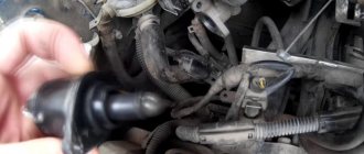
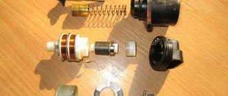
Assembly of gearbox components
The sequence of stages for assembling the drive shaft 11 gearbox (Fig. 1):
- First, the ball bearing 12 is assembled (this operation is called subassembly), for which the retaining ring 13 is installed in the groove of the part.
- After this, the bearing is put in place on the drive shaft. The bearing groove must face outward.
Rice. 1. Gearbox parts: 1 – gearbox housing; 2, 3, 8 and 26 – gaskets; 4 – drain plug with magnet; 5, 17 and 55 – bolts; 6 and 56 – spring washers; 7 – hatch cover; 9, 13, 27, 37, 39, 43, 50 and 60 – retaining rings; 10, 19 and 38 – roller bearings; 11 – drive shaft; 12, 16, 28 and 59 – ball bearings; 14 – drive shaft bearing nut; 15 – drive shaft bearing cover; 18 – reverse gear block; 20 and 35 – spacer bushings; 21 – gear block axis; 22 – axle stopper; 23 – oil filler plug; 24 – cover of the rear bearing of the intermediate shaft; 25 – thrust nut of the rear bearing of the intermediate shaft; 29 – intermediate shaft; 30 – gear key; 31 – gear of the second gear of the intermediate shaft; 32 – reverse gear of the intermediate shaft; 33 – third gear of the intermediate shaft; 34 – fourth gear of the intermediate shaft; 36 – constant mesh gear of the intermediate shaft; 40 – plug; 41 – sealing ring; 42 – synchronizer for fourth and fifth gears; 44, 47, 51 and 65 – thrust washers; 45 — fourth gear gear of the driven shaft; 46 – fourth gear bushing; 48 — gear of the third gear of the driven shaft; 49 – synchronizer for second and third gears; 52 – gear of the second gear of the driven shaft; 53 – gear of the first gear of the driven shaft; 54 – driven shaft; 57 – fitting stopper; 58 – fitting; 61 and 67 – speedometer drive gears; 62 and 68 – driven gears of the speedometer drive; 63 – oil seal; 64 – driven shaft flange; 66 – flange nuts
- The bearing is pressed on after placing the drive shaft on the press table, where a special device is provided. To do this, use a mandrel, which is used to completely drive the part onto the shaft journal.
- Using a torque wrench, tighten nuts 14 with a force of 20 kgm.
- To prevent accidental unscrewing, the collar of the part is cored into the groove of the drive shaft.
- After installing the unit on the press table in a special device, grease is used to lubricate the internal gear seat.
- The rollers 10 of the bearing are put in place.
Important! The last of the rollers must be inserted freely, tension must be avoided. After completing this stage, it is checked how easily the installed rollers rotate. Rotation should be free, but without falling out of the seat.
- Before installing the rollers, they are checked to ensure they belong to the same size group. Permissible deviations from the established dimensions for each of the three groups: 8.0 – (0.003-0.008) mm.
- 8.0 – (0.005-0.010) mm.
- 8.0 – (0.008-0.013) mm.
Interesting: The installation of a roller bearing assembled into a cage began in 1967, when it was decided to switch to this method instead of installing individual rollers. This is caused by the need to extend the service life of the front bearing, on the one hand, and the desire to simplify the process of assembling/disassembling the gearbox.
- The retaining ring 9 is put in place after the rollers 10 are installed in the groove.
- Before the operation of assembling the 2nd and 3rd gear synchronizer begins, three supports of the locking device are placed in the fixture. The milled part of the surface of the supports (flat) should face outward.
- After installing the supports that serve as locking pins, you need to align the holes. Then rings are pressed onto the outer sides.
- The clamps are assembled (there are three of them; you need to assemble balls and springs), which are placed in a seat in the carriage.
- The second ring is assembled using the same pattern, which is then driven into the locking pins.
Important! It is necessary to ensure that the outer edges of the ring fit well against the end surfaces of the locking pins.
- Crimping of the fingers with a ball on both sides is carried out after installing the carriage in the device with a force of 4600 kg.
- After assembling the synchronizer, you need to use a special device (Fig. 2) to check the force required to remove carriage 2 from the central position.
Rice.
2. A device for testing the synchronizer for activation force. Testing the synchronizer consists of creating a load of a certain magnitude in order to turn on the synchronizer. The load confirming the suitability of the synchronizer is 20 kg. When checking, the carriage should be in the neutral position. The load is performed using handle 4 and should be smooth. To check, the synchronizer must be installed on the centering conical sleeve 1.
The assembly of the intermediate shaft 29 (Fig. 1) begins with pressing on the gears:
- Lubricant is applied to the shaft splines.
- Then a key 30 and a gear 31 of the second gear are installed in the groove.
- The shaft is fixed in bracket 6 on the prism of stand 5 (Fig. 3). The force required for fixation is provided by the brake chamber rod 7. The brake chamber is controlled using the handle 4 of the pneumatic valve.
Possible gearbox breakdowns
It is possible to determine whether the gearbox is broken or not by the characteristic sounds. Signs of trouble:
- the occurrence of loud noise;
- spontaneous activation of gears;
- oil leak.
If there is strong noise from the transfer case, it is advisable to check the condition of the gears and bearings. These elements must be replaced. When the teeth wear out, the driver may encounter problems such as spontaneous gear shifting.
You need to pay attention to the condition of the sealing elements. With prolonged use of the vehicle, they quickly lose their working properties.
This is the reason why fluid will leak. The membrane in the pneumatic chamber and fastenings must be checked.
Assembling a gearbox from components
For this operation, stands with one or several posts are used (Fig. 6); a hoist is used to feed the stand.
- First you need to fix the replacement head 2 on the gearbox housing 3.
- Using a hoist, move the head attached to the crankcase and the crankcase itself to the site of the assembly operation. The parts necessary for work must be prepared in advance and placed next to the stand.
Rice. 6. Multi-station stand for gearbox assembly
- The holes are closed: plug 23 (Fig. 1) is screwed into the oil filler, and a special plug 4 with a magnet is also screwed into the drain.
- The locking ring 39 is put into place in the crankcase 1 using pliers.
- A roller bearing 38 is put on the intermediate shaft 29. After the bearing is put on the front end of the shaft, it, together with the gears, is installed in the crankcase 1. The order of installation is as follows: the rear end of the part is inserted into the ball bearing socket, after which the front end is inserted into the outer ring end. This end of the shaft is installed along with the bearing.
- The stopper 27 is pressed onto the rear end of the shaft after the ring is put on the ball bearing.
- Using a mandrel, the rear end of the shaft along with the bearing is inserted into the seat in the crankcase.
- The nut 25 on the thread of the shaft 29 is tightened using a torque wrench.
- The core is done by pressing the end of the nut into the groove.
The shaft, after installation in the crankcase, should be rotated by hand movement without difficulty. This shows that its assembly and installation were carried out correctly. To do this, the cover 24 is placed on the seat of the rear ball bearing 28 with the fasteners, which were assembled together with washers 6 and spacers 26, tightened by 3 threads. After installing the cover and preliminary tightening, the final tightening is done with a force of 2.0 to 3.5 kgm.
Assembly sequence for the reverse gear block:
- Spacer sleeve 20 is placed between roller bearings 19, which are placed in the block through a technological hole.
- When the unit is lowered into the crankcase 1, the axis 21 of the block must fall into the hole intended for it in the crankcase.
- Pressing is done with a copper hammer. The block axis is pressed in until the end of the groove rests on the plane of the crankcase.
- The stopper is placed in such a way that it fits into the groove of the axle.
- The stopper fasteners are tightened with a force of 1.5 to 2.0 kgm.
- The hatch covers are assembled, installing fasteners with spring washers and gaskets, then placed in place in the crankcase. The tightening force should be up to 2 kgm.
- Using a mandrel installed in its place in the crankcase 1, the intermediate shaft plug 40 is hammered into the seat.
- Seals 41 are placed in the recess, which is in the seat of the front roller bearing.
In order to assemble the driven shaft 54 you need:
- Place it in gearbox housing 1.
- Using a special tool, install stopper 60 on the rear ball bearing 59.
- After this, the bearing with a stopper is installed on the shaft. The groove on the stopper should face outward.
- Using a mandrel and a hammer, the bearing is pressed onto the shaft and into the seat in the crankcase.
- The speedometer drive gear fits onto the end of the driven shaft, which protrudes from the crankcase.
- Then, using a mandrel, it is pressed into the bearing until the end.
Engine for ZIL. Topic started by Jack
Tell me, will the YaMZ-236 engine fit on the Zil-130 instead of the gasoline 8 and what gearbox and rear axle should I install???
.I just have an idea to build a truck tractor on a long ZIL-130 wheelbase. Andrey (Aias) 100% what will fit if the cab is 131, the original 130 is in question, it’s better to install a MAZ box, and if you find a casing, it’s better to use a KAMAZ box with a divider.
Alexander (Socrates) The ZIL itself was developed. There was even a prototype made on the basis of the ZIL-130. The gearbox is better than KAMAZ with a divider, and the rear axle is either KAMAZ or RABA
Denis (Macario) But won’t your frame burst in a couple of thousand.
Alexander (Socrates) You can consider an option with some kind of Japanese diesel engine. It is lighter than 236, but can be equal in power
Nikolay (Ffransis) ——————–
Roman (Razanah) used to install diesel engines from the MTZ-80 on collective farms and it works well.
Alexander (Socrates) Engines are still supplied from MTZ (D-240; D-245).
236 also stands up normally if the cabin is a new model.
Sergey (Obayana) Dmitry, my friend did it and it didn’t work out. The 130 is not included, you need the kadin 131 and the lining, but the internal combustion engine needs to be raised above the frame by 6-7 cm and on the springs by 10 cm under the hood there is no room to redo the pan at all, the gearbox is from MAZ, hfostovik high connect to the original axle, the problem is that the cardan has a kink angle of attack of more than 30 degrees, they installed the rear axle with 131 weak, the rear axle from Kamaz was considered, but this porekt ended, they threw everything away and put 240 on the original gearbox and axle, but for the saddle the internal combustion engine is weak, 6 tons, it’s hard for him and also about the Mazda ICE in front of the heavy ass, the driver doesn’t eat a little bit of snow when he climbs, advice - DON’T WORRY
Ruslan (Rayanna)
Ivan (Haruka) Ruslan, the 236 engine will fit, but you need to raise the cabin, or leave the Zilov radiator. But with Zilovsky it is not known how the cooling will be under heavy loads
Alexey (Vanja) How to plant it in the frame, the deeper the better
Sergey (Obayana) Selling 2.0 engine 10 thousand km. mileage, 135 mares, gasoline, with manual transmission, transfer case, all-wheel drive, there is a cardan, gearbox, wires, cams, rocker, pedals, wiring and much more.
Sergey (Obayana) SMD is installed with a DT 75 and a Niva combine harvester. It sings with a turbine but the speed is weak
Ignat (Vikram) great guys, I wanted to know your opinion that if the engine is boiled in a ZIL 130, what could this affect? Tell me, who knows if it’s not difficult
Ignat (Vikram) or is it already junk
Groundhog (Justica) Selling a w124 602 2.5 diesel engine with all attachments. The attachment includes the entire swap kit to install and start, right down to all the pipes, etc., + radiator and exhaust. Price RUB 30,000. The engine is on the car and can be started. city of St. Petersburg
Kirill (Chuki) But the bridge won’t go from punishment, the Mazovsky one will go, it will be as big as a hundred pounds and then there will definitely be a beast
Kirill (Chuki) When you move out of a place, the load goes to the rear, and the Karovskiy won’t withstand such a load; the gear will break under heavy load, so safely put on the Mazovskiy
SYNCHRONIZER
Synchronizers ensure silent operation when turned on. The difference in the rotation speed of the synchronizer clutch and the engagement of the gear is smoothly equalized due to the friction force that arises between them. The gearbox shift mechanism has a locking device that holds the shift rods in the required position.
Synchronizer ZIL-130
The synchronizer for LAZ-695, LAZ-697 buses and the ZIL-130 car (Fig. 132) works as follows.
When clutch 11 is moved to the left using the shift fork, the conical bronze ring will move with it and press against the conical surface of gear 1. The conical rings 7 and the clutch ]] are not connected rigidly to each other, but through three locking pins 5 with balls and a spring. Gear 1 and rings 7 rotate at different peripheral speeds. Until these speeds become equal due to the friction force, coupling 11 will shift (Fig. 132, b).
Synchronizer ZIL-130
Both bronze rings 7 are rigidly connected to each other using pins 12. The coupling 11 will move until the conical surface 10 of the coupling rests against the conical surface 9 of the pin (Fig. 132, a and d). When the speeds of the synchronizer rings 7 and the gear cone 1 are equalized, the pin 12 will be located in the center of the hole of the coupling 11, the blocking conical surfaces will separate (Fig. 132, c and d), and the coupling will continue its displacement. Its outer teeth 13 will engage with the inner teeth of the gear shaft 1, which will thus be connected via a synchronizer to the driven shaft 14.
Homemade equipment and devices Topic author Sergey
Hello, tell me how to make axle blocking on ZIL 131 that can be switched on and off. Thank you in advance
Seryoga (Dakheel) brew a differential and install hubs! or look for a ready-made factory one
Sergey (Fychan) this is not a solution
Vladimir (Roly) Where do you want to drive 131 on the blocking? If he sits on the bridges, then blocking will not help, but to get him out of there.....
Sergey (Fychan) yes, but with blocking he would have walked much more cheerfully and confidently and would have gotten stuck less
Vladimir (Roly) If you hit him on the blocking, then what will you use to get him out? Turn out all his insides. This is not GTS
Anatoly (Boulos) Even without blocking, the middle gearbox is breaking!
Oleg (Katleen) ...axles or gearboxes from ZIL 4334, with differential locking - pneumatic drive!!!!!!!!!!
Peter (Ditrik) The best locking is a winch that has been tested, as long as there is something to grab onto. I have a Zil 131 with an engine from Bychka, it goes very well in the mud; it is low-speed compared to a gasoline engine; I installed it myself
Anatoly (Boulos) You can get by with a winch as a last resort
Victor (Friedegunde) Hello! I'm now trying to install diesel from a bull on 131. I would like to know how the original pallet becomes or not?
Peter (Ditrik) Victor, install it, don’t bother, everything fits, the only thing that will have to be remade is the gas drive, the Bychka engine, as it was, the Glushak still needs to be redone, and if there is a Bychka gearbox, install it, and if not, then on Zilovskaya, shorten the input shaft by about 50mm if anything else is needed contact me, I’ll help you drive through the forest, there’s enough dope and I made the lower pipe, inserted one into the other with different diameters and everything will fit
Victor (Friedegunde) I have a ZIL 131 gearbox. Is it different from the bull gearbox? I took the clutch housing from 131
Vladimir (Roly) gearbox - bull and gearbox ZIL-131 are different things!!! I have a GAZ-66 engine D-245 and a gearbox with a bull speed of max 90 km, h,,,, put the box with 131 speed disappeared max 65-70 km, h and they look the same!!!!
Oleg (Katleen) THE BULL HAS 5 INCREASED A ZILA 130 131 DIRECT)
Victor (Friedegunde) Is the length of the input shaft different?
Vladimir (Roly) Bychkovsky lane shorter
Victor (Friedegunde) Thank you!
Vladimir (Roly) Of course!!!
Sergey (Fychan)
Sergey (Fychan) This is a Polish car STAR 660, an analogue of the ZIL 157; it has all the axles with a differential lock, which is activated by an air chamber of the brake type. And the axles are completely copied from the ZIL 157. Go to Poland and the issue of blocking has been resolved.
Reverse gear – ZIL 41052 – YouTube
More test drives every day - subscribe to the channel - Join AUTO PLUS...
Transfer case car ZIL 131: technical...
To be sure that the ZIL 131 car has a transfer case... The front axle has an electro-pneumatic switch. ... The box housing itself is made of cast iron, it is detachable, the rear part .... half of the driven shafts have the same angular velocity, and the other... Clutch on ZIL 130.
DIY repair
If malfunctions and breakdowns occur in the operation of the rocker or other element of the power take-off box, the only option for troubleshooting is to repair the unit. To carry out repairs, it is necessary to disassemble the ZIL gearbox with a diesel engine, replace the failed components, and then reassemble all components.
To carry out repairs yourself, you will need a special table with a stand; without it, assembling transmission parts is impossible.
The Mudo channel in its video showed how to replace the bearing and seals on the gearbox input shaft.
How to assemble transmission components?
First, the drive shaft is assembled:
To assemble the intermediate shaft, the gears are pressed in:
User Vladimir Pivinov showed in the video how to repair a gearbox if the fifth gear falls out.
The driven shaft is assembled like this:
User Vasily Panchenko in his video showed how he knocks out the input shaft on a ZIL transmission.
The procedure for assembling and disassembling the gearbox shift mechanism is performed using a special tool.
Finding such a device on sale is problematic; you should look for it at a service station:
The last assembly that remains to be assembled is the transmission shift lever:
Diagram of a device for diagnosing synchronizing devices for activation force Stand for pressing gears onto transmission shafts Special stand for assembling a ZIL gearbox
How to assemble the transmission?
To install and assemble all components into one unit, you need to use special stands that are equipped with one or more posts:
User Andrey Sverdlov in his video explained what nuances should be taken into account when assembling the ZIL transmission unit.
