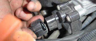
1. Release the clamp of the wiring harness block and disconnect the block from the idle speed control.
The terminals are marked on the idle air control block.
2. Connect the negative probe of the engine voltage.
3. Having turned on the ignition on the VAZ car, use a voltmeter to measure the voltage at terminals A and D of the idle speed control block.
ATTENTION The voltage on the idle speed regulator block must be at least 12 V (the negative probe of the device must be connected to the engine ground). If the voltage does not reach the idle speed control block or it is less than 12 V, the battery is discharged, the power circuit is faulty, or the ECU is faulty.
4. After completing the voltage measurement, turn off the ignition on the VAZ-2104, VAZ 2105, VAZ 2107.
Removing the idle speed regulator from a VAZ-2104, VAZ 2105, VAZ 2107 car
1. Remove the throttle body.
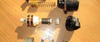
2. Using a Phillips screwdriver, unscrew the two screws securing the idle air control to the throttle body.
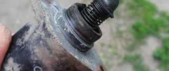
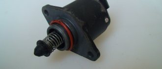
3. Remove the idle speed control. An O-ring is installed in the connection between the VAZ idle speed control and the throttle body. Replace a ring that has lost elasticity or is cracked.
4. Using an ohmmeter, we measure the resistance between the terminals of the windings of the idle speed control VAZ-2104, VAZ 2105, VAZ 2107.
The electrical resistance between terminals A-B and C-D should be within 52-53 Ohms. The resistance between terminals A-C and B-D should be high (tend to infinity). The faulty idle air regulator on a VAZ car needs to be replaced.
ATTENTION Before installing a new idle air regulator on a VAZ-2104, VAZ 2105, VAZ 2107, you must make sure that the valve needle protrudes no more than 23 mm.
5. Using a caliper, measure the protrusion of the needle of the new valve.
6. If the needle protrusion is more than 23 mm, its position must be adjusted. To do this, we apply 12 V voltage from the battery to terminal D of the idle air control regulator (the connection of the wire to the terminal must be insulated). With the bare end of the wire connected to the negative terminal of the battery, briefly touch terminal C of the idle speed control.
Since the valve moves slowly, we touch it repeatedly, simulating the operation of a switching power supply. After installing the needle in its extreme position, check the protrusion of the needle, which should be 23 mm. Otherwise, replace the valve with a new one.
Installation of an idle air regulator on a VAZ-2104, VAZ 2105, VAZ 2107 car
1. Apply engine oil to the sealing ring.
2. Installation of the idle air regulator is performed in the reverse order.
Quite often, a violation of the idle operation of the internal combustion engine in the seventh model of Zhiguli is associated with the failure of the idle speed controller. The breakdown occurs if the car is equipped with a VAZ 2107 idle speed sensor for the injector, and in the carburetor circuit for supplying the fuel mixture, the valve responsible for the supply periodically fails.
Features for injector and carburetor
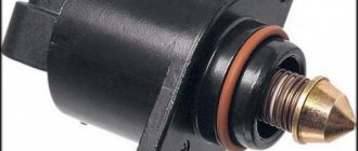
The idle speed regulator (sensor) belongs to the fuel system of an internal combustion engine with distributed injection. The purpose of the part is to open the air pipe into the receiver when the throttle valve is closed within strictly defined limits.
Structurally, the IAC on the VAZ 2107 is an electric motor, which consists of a stator, a magnetic rotor and a spring-loaded rod mechanism with a locking tip. The ECU sensor controls the opening of the damper to a certain area.
For carburetor engines, a different solenoid valve operation scheme is used. The regulator is installed in the carburetor; it is based on an electromagnet with a locking part. When voltage is applied from the ECU, the valve releases passage in the fuel nozzle.
Speed and revolutions: fuel savings and engine life
So, you can often hear from drivers that as soon as the car accelerates to 60 km/h, you can engage, for example, 5th gear (if the gearbox is 5-speed). In this case, the speed will drop to 1900-2000 thousand rpm and in this mode fuel consumption will be minimal. In other words, the most economical option is to drive when the highest gear is engaged and the speed is low.
If you study the theoretical part a little, accelerating to a certain speed will require energy expenditure. The more intense the acceleration occurs, the more energy is consumed. After reaching a constant speed (cruising), fuel consumption becomes less, but it must be taken into account that the car also overcomes air resistance.
Without going into mathematical calculations, an increase in speed, for example, from 50 km/h to 100 km/h will mean that air resistance increases not by 2 times, as many might think, but by as much as 8 times. That is, to maintain the current speed, you will need to expend 8 times more energy. It is to overcome air resistance that engine power is expended.
It turns out that to maintain a speed of about 50 km/h, you need about 30-35 hp, while when accelerating to 120-130 km/h, 80-90 “horses” are needed to overcome resistance to air flows. To this you need to add the mass of the car itself, which is different for each vehicle, make allowances for road conditions, etc.
You also need to remember that piston internal combustion engines demonstrate the best efficiency in the zone of maximum torque, and not maximum speed. At the same time, it should be taken into account that the gearboxes are also different and have different gear ratios.
It becomes clear that the most economical mode is actually achieved when the car is moving in top gear at a low speed, but the optimal speed in such a gear will be different for each car.
Another important point is, let’s say, the feasibility of saving fuel in this way. In the manual, many car manufacturers specifically indicate that you need to switch to the highest gears not at 50, but at 80 or even 100 km/h. The fact is that the lower the engine speed, the more the consumption drops, however, such driving at low speeds and in high gears can harm the engine.
For example, a 2.0 liter engine in a car weighing about 2 tons, which is moving in high gear at a speed of about 60 mph, will operate at low speed. In this case, the load on the motor will be very large. The fact is that the oil pressure at low speeds is also low, that is, the wear of parts and components of the power unit is maximum.
To reduce the load, you need to either add speed and increase the speed, or switch to a lower gear. If a car with the same engine weighs, for example, 1.3 tons, the load on the internal combustion engine will be less than in the case of a two-ton car, but accelerated engine wear will still be present.
If we summarize the information received, then it becomes clear that the lower the speed and the higher the gear, the lower the fuel consumption. At the same time, driving at low speeds “kills” the engine. This results in very dubious savings on fuel, which in no way covers the costs of engine repairs in the future.
Location of the sensor on the VAZ 2107
In injection engines, the sensor is located on the intake manifold in the throttle block.
In carburetor engines, the control solenoid valve is located in the unit block.
Types of regulators
Externally, the unit looks like an electric motor equipped with a conical needle. There are several variations of the part:
- stepper - consists of a ring magnet and windings. The main rotor is rotated by stepwise supply of energy to the circuit components using electromagnetic force. The movement of the rod is carried out by an actuator taking into account the location of the rotor;
- solenoid type - the simplest type. The supply of energy to the winding activates the core. It moves into a special hole, reducing the diameter of the air channel. As a result, the supplied air volume decreases. Due to its simplicity it has the lowest cost. Its operation is carried out only in the open or closed position;
- rotary - the intake of air mass is controlled using frequency pulses, the main load goes to the rotor. The device resembles a solenoid regulator.
Signs of breakdown
Problems with engine operation during idling are not always associated with a malfunction of the fuel system. For carburetor engines that use a classic ignition circuit, a jumping stroke in 70% of cases is associated with a broken group of contacts and incorrect carburetor settings.
The carburetor magnetic valve operates only when the ignition is on. Therefore, before repairing a part, the quality of the power supply to the central wire of the carburetor and the integrity of the circuit are checked. Causes of unstable engine idle speed:
- The carburetor is clogged with dirt.
- The winding in the IAC has burned out.
- Clogged jets, fuel or air filter.
- Incorrect carburetor setting.
The first signs that the IAC has burned out on an engine with a distributed injection system:
- Unstable operation of the internal combustion engine (stalls if the accelerator is released, troits).
- The revolutions float (decrease or increase).
- The engine power decreases and a difficult start is felt.
If the regulator is burnt out, the engine computer signal system does not display the CHECK error on the instrument panel, so the part is diagnosed based on the symptoms when checking the system.
Reasons for high speed on the injector
On the injector, the reasons why the speed increases can be divided into:
- related to electronic malfunctions;
- associated with mechanical problems.
In the first case, the sensors or controllers are acting up. In case of malfunctions of this kind, it is best to seek the help of specialists.
Throttle valve
If the reason lies in the poor functioning of the throttle valve (in most cases, it becomes jammed), the following happens:
- the volume of air entering the cylinders increases disproportionately;
- The ECU will "demand" more fuel to balance the mixture.
As a result, the car will not only consume much more fuel than it should, but it may even fail due to constant “overload” at high idle speeds. Diagnostics of the damper and, depending on the diagnostic results, chemical cleaning or replacement will help resolve the problem.
Engine temperature sensor
This device is considered subject to frequent failures, since it is located in the epicenter of inevitable temperature changes. If it was noticed that with certain initial conditions everything is in order with the motor, but the sensor is “playing naughty”. To diagnose, you will have to delve into the wiring.
With the ignition on you need to:
- take data on the resistance from contact “A” to ground (the exact correct value is 10 Ohm);
- take data on the resistance from ground to terminal “B” (if less than 10 Ohms, you need to sound the alarm;
- also take data on the voltage at terminal “B” in relation to ground (the exact correct value is 5V).
There may be a problem with the sensor itself. To determine this, you need to take the above resistance readings with the engine cooled down and warmed up. When working properly, the readings should not differ.
Engine temperature sensor
Air flow sensor
The oil film that envelops this device during vehicle operation eventually leads to malfunctions of the element that measures and sends a signal to the computer about the amount of incoming air (hot-wire anemometer). As a result, the ECU does not have access to reliable information about the amount of air, and the speed begins to float. But first of all, it is worth inspecting the air filter. Perhaps it is simply clogged and air is not flowing freely.
Intake manifold
High speeds may be associated with air suction. There can be two types of faults in this unit:
- deformation of the intake manifold;
- breakdowns or burnout of the gasket.
If the second case is not so catastrophic, then the first will most likely lead to a call to the services of a car service, since grinding may be required. Problems will be detected, including when the engine warms up.
Other reasons
Other common reasons may be the following:
- jamming of the gas pedal, which is typical for both an injector engine and a carburetor engine;
- On the injector, the IAC (idle air control) and TPS (throttle position) sensors may fail: if there is a suspicion that it is they who are “sinning,” you will need to check the contacts;
- ECU failures, which are checked using special computer programs;
- the generator does not supply the required current rate, so the motor will begin to accelerate in pursuit of the required voltage;
- For cars with a turbocharger, high speeds at idle can be caused by its wear or depressurization of the rotor shaft gasket.
If you cannot confidently identify the cause of the increase in speed, it is more prudent to contact specialists (especially in the case of an injector).
Intake manifold with throttle valve
Diagnostics of IAC electrical wiring
Before replacing or cleaning a part, check the supply circuit with a multimeter. The order of ringing the chain step by step:
- Locate the sensor wires in the electrical cable block.
- Disconnect the block, turn on the ignition.
- Switch the multimeter to voltmeter mode, connect the minus probe to ground (car body).
- Plus, alternately apply “A” and “D” to the output.
If the voltage is similar to the parameters of the on-board electrical network (approx. 12 V), the supply circuit is in order. If the voltage is less than 10 V or there is no voltage at all, check the car's wiring.
Signs of malfunctions
The IAC is not the most vulnerable element of the engine, but its failure is quite possible.
But the IAC belongs to the category of automotive actuators, and therefore, if it breaks down or a malfunction occurs on the dashboard, the Check light does not light up.
Regulator malfunctions can be identified by the following symptoms:
- When the internal combustion engine is at idle speed, the engine behaves unstable. Sometimes the engine may stall spontaneously if the speed is not maintained with gas.
- Without any reason, the speed increases or decreases.
- When changing any gear, the engine may stop completely. A similar situation can occur when starting from a standstill.
- When a cold engine starts, it does not operate at high speeds.
- When you turn on the headlights or the interior heater, the idle speed drops.
Cleaning the regulator or completely replacing it can help troubleshoot problems. Cleaning and then rinsing the part yourself is not difficult, nor is changing the element. But in both cases it is better to first dismantle the controller.
To do this, turn off the engine and remove the negative terminal from the battery. Next, the regulator contact connector is disconnected, the housing mounting bolts are unscrewed, and the problematic element is dismantled.
Cleaning does not help in all situations. Before installing a remanufactured or new regulator, the flange O-ring should be lubricated using engine oil.
It is quite easy to calibrate the unit with your own hands. To do this you need:
- check the distance from the mounting plate to the end of the rod and make sure that it does not exceed 23 mm;
- disconnect the minus from the battery;
- install a new valve;
- return the negative terminal to its place;
- turn on the ignition for 5 seconds, but do not start the engine;
- wait for automatic calibration;
- turn off the ignition;
- fully start the engine and watch how it idle.
The XX regulator is an important component of any engine. At the same time, its diagnosis, replacement and repair should not cause any particular difficulties even for a beginner.
Replacement
Diagnostics, cleaning and replacement of the throttle body is carried out after removing the throttle unit from the car.
The sensor is carefully removed from the dismantled unit and inspected. To check the performance of the dhx, use a tester switched to ohmmeter mode. Step by step diagnostic procedure:
- Set the measuring range on the tester to 0-200 Ohm.
- Attach the probes to the terminals, first on “A” and “B”, then “C” and “D”. The working element will show a value within the range of 50-53 Ohms.
- Take measurements between opposite pairs: “A” and “C”, then “B” and “D”. On a working unit, the instrument readings should tend to infinity.
If the electrical parameters are normal, the rod is measured - the overhang length should not exceed 22 mm.
If the rod is jammed, its size is increased, there are no optimal indicators of the multimeter, the part is changed. It is not advisable to repair the sensor.
Device diagnostics
Motorists are interested in how to check the idle air valve themselves and its current condition.
For many car enthusiasts, independently checking this valve, a component of the idle air system, is a completely doable task. There are several methods for diagnosing the condition of the regulator.
- Visual inspection. First a visual inspection is carried out. This allows you to determine the presence of defects on the body, signs of needle wear, and signs of carbon deposits on surfaces. If there are deposits, they can be removed using carburetor cleaner. Surely, if the IAC is dirty, the entire throttle assembly will be dirty. Therefore, it will not be superfluous to clean it too.
- Diagnostic software. Some car enthusiasts are switching to using special diagnostic programs. In addition to the software, an adapter is also required to connect to the system. Through the software menu, the position of the controller is selected and its operation is observed.
- Wiring condition. It would not be superfluous to carefully check the wiring connected to the IAC. Here you need to use a multimeter. The engine is turned off, the sensor connector is removed. On the multimeter, select the voltage test mode with a limit from 0 to 20 V. When working properly, the device should show about 12 V.
- Resistance. The resistance of this regulator is also checked. To do this, using the same multimeter, the resistance between the terminals is checked by disconnecting the sensor terminals. The multimeter is turned on in resistance mode, and the limits are set from 0 to 200 Ohms. The terminals are conventionally designated as A, B, C and D. When measuring resistance at A and C, as well as at B and C, the device should display infinity. In other cases, 50-55 Ohms is considered the norm.
- Check with throttle. Checking with the throttle assembly is also quite common among motorists. The complexity of the method is that you will have to completely dismantle the entire throttle assembly directly along with the sensor itself. After connecting the IAC connector, turning the ignition on and off, visually observe the operation of the suspected regulator. Make sure that the needle moves normally, the stroke is uniform, and there are no extraneous sounds.
In most cases, when the IAC fails, it is replaced with a similar part.
Features of tuning carburetor engines
In the VAZ 2107 engine, the carburetor uses an undistributed fuel mixture supply circuit, there is no idle speed sensor as such in the system, the operation of the entire solenoid valve block is checked: jets, spring-loaded mechanism and power quality.
Malfunctions can be eliminated by flushing the carburetor, cleaning the jets and channels. It remains mandatory to adjust the fuel level in the float chamber and check the jets for compliance with the markings, since the parts have different sizes.
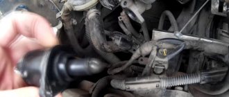
And that's how it all started. It started with the fact that in the summer, on those very days when the sun is hot on the belly and you want something cooling, I noticed that the baby began to mope, namely, to jump in speed. I think what's the joke? Since I have already said that I am a techie and I think it is necessary to figure out what’s going on. I followed the simple path through trial and error. I started disconnecting the sensors one by one and found out that the Idle Air Control sensor (hereinafter referred to as IAC) had preserved its brains.
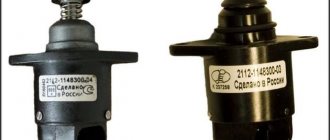
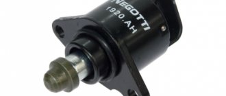
I went to the spare parts store for the boys and the superman for spare parts gave me a sensor, and I mentioned that I have an injection pump and at the same time I’ll change the TPS sensor. I gave unrealistic hazel grouse for this pleasure and happily wandered to the place of the campicnic. I installed everything without problems, but this sensor (which is on the right in the photo) seemed cloudy to me.
But in the end everything stood up and worked as it should. After driving a couple of kilometers, I returned from my beloved and my gas pedal began to live its own life, namely, it did not return and did not want to be pressed. This caused the revs to jump again. As always, I’m slightly perplexed and think wow, this is a classic VAZ, everything here breaks and fixes itself, etc. and so on. I park in the hacienda, open the hood and look at the cable - everything is ok. I look closely, and the spring fastener on the throttle has fallen off
What a joke I thought. I took it apart and saw that oil appeared in the throttle, which should not have been there.
I cleaned the entire system, really blew smoke all over the yard like at a Rammstein concert, oh well, I changed the throttle to a new one (after suffering with its cooling pipes), but the problem with the speed remained. I thought that not caring about it would do. Then I drove around and learned to adjust everything with the clutch, which of course is not very correct. And so, before the New Year, I stopped by Auto 49 to pick up wipers and even asked about the sensor. To which Superman says to me: “The IAC sensors are not of high quality, they say, this batch arrived and we don’t know what to do since the summer.” I think it’s absolutely beautiful, you know, I’m driving around thinking what a fantasy it is, and it turns out they have a leftist lying down. Super easy! I went to my trusted spare parts at Petrashka. They gave me a sensor, and I say it already looks like a normal sensor (pictured on the right)
I arrive joyfully into a cozy courtyard, open the hood, take the screw, and try to unscrew the figurines. As a result, I had to remove the throttle and unscrew everything normally, I put the kit back together, turn the IGNITION key, all the strength and power of my engine comes together and it starts. Everything works like clockwork, pure bliss.
So people, having the hands, strength, time and endurance, can repair the cars themselves. And don’t forget that even in branded stores there are low-quality parts, always check if possible. What is my lesson now? All the best. And thank you for taking a couple of minutes to read this post.
Today I will tell you how to check the idle air sensor; by the way, the correct name is not the sensor, but the idle air regulator. Due to the fact that this device regulates engine idle speed, and does not read any indicators. Let's look at the breakdown of this sensor and what can be done about it using the example of a VAZ 2110 car, but the IAC is not much different in other cars. I forgot to say IAC is the Idle Air Controller in abbreviation. I myself often call it a sensor, so if later in the article you come across the words regulator or sensor, then don’t be too indignant.
Operating principle of IAC
The sensor installed on the engine (mass air flow sensor) determines the volume of incoming air and sends a signal to the ECU, which “gives a command” to “send” the required amount of fuel to the injectors. At the same time, the control unit takes readings from the crankshaft position sensor and controls the operation of the IAC. The last action is expressed in issuing a “command” to open an additional channel.
Another function of the IAC is to adjust the idle speed (700-900 per minute) depending on the engine warming up. If the temperature is insufficient, the ECU “orders” the sensor to increase the passage of the channel: as a result, more air enters the combustion chamber, and the control unit simultaneously supplies more fuel - as a result, the speed increases and the power unit warms up faster. In the same way, using IAC, the ECU takes into account changes in the load on the engine associated with the connection of additional consumers: for example, headlights, interior heater, heated rear window, mirrors, seats, etc. As a result, the engine operates stably at any load.
Symptoms of a broken IAC sensor
I will give several examples of how a car can behave if the idle air control valve breaks down. There are also a few examples of how you can independently discover that your IAC is not working.
- The first situation
and the most obvious way to detect the appearance of the Check Engine indicator on the dashboard. Using your phone or laptop, you can connect to your vehicle and find out why the Check Engine message is appearing. - The second situation is
“Floating idle speed”, the engine spontaneously increases speed, then decreases. Sometimes the spread of such fluctuations can reach several thousand. - Third situation
. The engine starts and immediately stalls, but continues to run if you press the gas pedal. - Fourth situation
. The engine needs much more time to warm up and reach normal operating mode, and until this point, unstable operation appears.
General concepts and operating principle
A sensor is a specialized device belonging to the group of measuring instruments, used for processing and converting data, as well as displaying it on a mechanical or electronic display in the form of an understandable digital value.
As it becomes clear, IAC is not a completely rational name for the device in question; it would be more correct to say - idle air control (IAC).
So, the idle air regulator is one of the most important components of an internal combustion engine and plays a significant role in the smooth and uninterrupted operation of the car as a whole.
The idle speed control is an actuator, malfunctions of which are very difficult to identify with your own hands.
This is explained by the fact that the systems of VAZ cars do not provide for its self-diagnosis - in case of various malfunctions and malfunctions in the regulator, the “check engine” indicator light does not light up.
Where is the idle speed sensor located?
Different cars have different equipment and different locations of sensors and power units in the engine compartment. However, on any car you need to start looking for this sensor from the air intake unit. Since it is the IAC that regulates the flow of air for mixing with gasoline.
Using the VAZ 2110 as an example, let’s pay attention to the far part of the engine from the passenger compartment.
Irregularities in the operation of the VAZ 2107 engine at idle speed are a fairly common phenomenon. And if we are talking about a power unit with distributed injection, then very often the cause of such problems is a malfunction of the idle air controller (IAC). We will talk about it in this article.
Not enough air
Often the car starts up well and runs on choke, but as soon as the choke is turned off, the engine stalls. This indicates only one thing - lack of air. Most likely the air jets are clogged. They need to be unscrewed and cleaned. Then check that the car should not stall without suction.
There are an incredible number of reasons for poor performance of car components with similar symptoms, but only a specialist with a set of professional diagnostic tools can figure them out. But if you feel confident in yourself, go for it, VAZ service centers are already waiting for you.
If you find an error, please select a piece of text and press Ctrl+Enter.
Source
Idle speed regulator (sensor) VAZ 2107
In everyday life, the IAC is called a sensor, although it is not one. The fact is that sensors belong to measuring equipment, and regulators belong to executive equipment. In other words, it does not collect information, but executes commands.
Purpose
The IAC is a component of the fuel supply system of an engine with distributed injection, regulating the volume of air entering the intake manifold (receiver) when the throttle valve is closed. In fact, this is an ordinary valve that slightly opens the spare (bypass) air channel by a given amount.
IAC device
The idle speed control is an electric motor of a stepper design, consisting of a stator with two windings, a magnetic rotor and a rod with a spring-loaded valve (shut-off tip). When voltage is applied to the first winding, the rotor rotates to a certain angle. When it is fed to another winding, it repeats its movement. Due to the fact that the rod has a thread on its surface, when the rotor rotates, it moves back and forth. During one full revolution of the rotor, the rod takes several “steps”, moving the tip.
Operating principle
The operation of the device is controlled by an electronic unit (controller). When the ignition is turned off, the IAC rod is pushed forward as much as possible, which is why the passage hole of the bypass channel is completely blocked, and air does not enter the receiver at all.
When the power unit starts, the electronic controller, based on data received from temperature and crankshaft speed sensors, supplies a certain voltage to the regulator, which, in turn, slightly opens the flow area of the bypass channel. As the power unit heats up and its speed decreases, the electronic unit through the IAC reduces the flow of air into the manifold, stabilizing the operation of the power unit at idle.
When we press the accelerator pedal, air enters the receiver through the main channel of the throttle assembly. The bypass channel is blocked. To correctly determine the number of “steps” of the device’s electric motor, the electronic unit additionally uses information coming from the throttle position, air flow, crankshaft position and speed sensors.
When additional load occurs on the engine (turning on the radiator fans, heater, air conditioner, heated rear window), the controller, through the regulator, opens a spare air channel to maintain the power of the power unit, preventing dips and jerks.
Where is the idle air control on a VAZ 2107?
The IAC is located in the throttle body. The assembly itself is attached to the rear of the engine intake manifold. You can determine the location of the regulator by the wiring harness that fits its connector.
Idle speed control in carburetor engines
In carburetor power units of the VAZ 2107, idle speed is ensured using an economizer, the actuator of which is an electromagnetic valve. The valve is installed in the carburetor body and is controlled by a special electronic unit. The latter receives data on the number of engine revolutions from the ignition coil, as well as on the position of the throttle valve of the primary chamber of the carburetor from the contacts of the fuel quantity screw. Having processed them, the unit supplies voltage to the valve, or turns it off. The design of the solenoid valve is based on an electromagnet with a shut-off needle, which opens (closes) the hole in the idle fuel jet.
Adjusting the idle speed of a car engine with carburetors 2105, 2107 Ozone
Adjusting the idle speed of carburetors 2105, 2107 Ozone and their modifications is one of the most frequently performed operations in carburetor maintenance.
As a result, it is necessary to achieve stable engine operation at a crankshaft speed of 850-900 rpm, as well as to normalize the content of CO and CH in the exhaust gases. If the idle speed is adjusted incorrectly, the engine may start and immediately stall, it may stall, during acceleration there may be a “failure”, and during operation there will be increased fuel consumption.
Tools required for adjusting XX speed
— tachometer (you can use the one built into the instrument panel) — slotted screwdriver (3 mm)
In the absence of a tachometer, it is possible to adjust the idle speed by ear. But for this you must have at least some experience in car repair, since it is necessary to distinguish when the speed is normal and when it is increased or decreased.
Preparatory work
Before making adjustments, you must first make sure that the ignition timing is set correctly. The distributor cover, breaker contacts, armored wire and spark plugs are in good condition.
If the carburetor is after disassembly and reassembly or you simply need to set the initial value of the adjustment screws, then first tighten them completely, and then turn out the “quality” screw by 1-2 turns, and the “quantity” screw by 2-3. More details: “How many revolutions should I turn out and tighten the “quality” and “quantity” screws of the Ozone carburetor.”
— Warm up the engine to operating temperature (85-95 0). — With the engine stopped, connect the tachometer and start it again.
The procedure for connecting an autotester (tachometer)
— Rotate the “quality” screw and set the maximum idle speed
We rotate the screw both counterclockwise and clockwise, trying to catch the optimal position of the “quality” screw at which the XX speed is maximum.
Rotate the “quality” screw of the carburetor fuel mixture 2105, 2107 Ozone counterclockwise and clockwise
— Use the “quantity” screw to set an even higher rotation speed
For example, 80 rpm more. We also rotate the screw both clockwise and counterclockwise, trying to increase the idle speed.
We rotate the “amount” screw of the fuel mixture counterclockwise, increasing the total amount of the fuel mixture entering the engine cylinders, clockwise we increase the amount of air and optimize the composition of the mixture (it burns better)
Simply rotating it back and forth.
We check by rotating the “quality” screw in different directions whether the set idle speed is maximum
If not, then we carry out the above adjustments again.
Notes and additions
If, after such an adjustment, the content of CO and CH emissions does not correspond to the norm or the idle speed cannot be adjusted, then it is necessary to check:
— whether the fuel and air jets of the main dosing system are dirty; — whether the main fuel jets of the first and second chambers are reversed; — whether the fuel level in the float chamber is increased; — Is the needle valve working? - Is the fuel jet of the idle system clogged; — whether the holder of the fuel jet of the idle system or the solenoid valve has turned away; — whether the tubes have come off the electro-pneumatic valve; — whether the rubber o-ring on the fuel mixture “quality” screw is damaged.
— In some cases, it makes sense to modify the carburetor idle system. See “Modification of the idle system of Solex and Ozone carburetors.”
Twokarburators VK - More information on the topic in our VKontakte group, on Facebook Twokarburators FS and on Odnoklassniki - Twokarburators OK
Signs of IAC malfunction
Signs that the idle air control valve is faulty may include:
- unstable idling (the engine troits, stalls when the accelerator pedal is released);
- decreasing or increasing the number of engine revolutions at idle (floating speed);
- reduction in the power characteristics of the power unit, especially with additional load (turning on the heater fans, radiator fans, heated rear window, high beam, etc.);
- complicated engine starting (the engine starts only when you press the gas pedal).
But here it should be borne in mind that similar symptoms may also be inherent in malfunctions of other sensors, for example, throttle position sensors, mass air flow or crankshaft position sensors. In addition, if the IAC malfunctions, the “CHECK ENGINE” indicator lamp on the dashboard does not light up, and it will not be possible to read the engine error code. There is only one way out - a thorough check of the device.
How to repair an injector in a VAZ-2107
If replacing the sensors does not produce results, it is better to go to a service station. The banal lack of tightness of the intake manifold provokes the same problem when the car stalls at idle.
With your own hands, inspect the vacuum hoses, gaskets, injector sealing rings, and then the plugs that are located in the manifold, and the vacuum brake pedal booster. It is easy to detect air leaks using a special unit called a smoke generator. Do not ignore checking the gasoline pressure.
If a pressure regulator is installed on the VAZ-2107 ramp, the optimal value fluctuates around 2.5 bar, but this is only at idle without a vacuum device. With a vacuum device, a value of 3.8 to 4 bar is permissible. Spark plugs must also be checked.
How to clean the VAZ-2107 injector nozzle is shown in the video:
Checking the idle air control circuit
Before moving on to diagnosing the regulator itself, it is necessary to check its circuit, because the reason that it stopped working could be a simple break in the wires or a malfunction of the electronic control unit. To diagnose the circuit, you only need a multimeter with the ability to measure voltage. The procedure is as follows:
- Raise the hood and find the sensor wiring harness on the throttle assembly.
- Disconnect the wiring harness block.
The voltage between ground and each of the terminals must correspond to the voltage of the on-board network, i.e. approximately 12 V. If it is less than this indicator, or is absent at all, you need to diagnose the wiring and electronic control unit.
Principle of operation
The idle speed sensor is a closed-type system and has feedback, that is, all components represent a conditional closed circle:
Accordingly, according to the scheme:
- Actuator - idle speed sensor;
- Sensor - any device that reads engine rotation speed (crankshaft or camshaft sensors);
- The object of regulation is the engine speed.
When the engine is idling, the throttle valve is in the closed position, and the required amount of air enters through the bypass (“bypass” - bypass), the width of the channel of which is determined by the XX sensor. The amount of air passing behind the damper is read by its mass flow sensor, and this directly affects the amount of fuel supplied through the injectors.
- The comparison circuit is an electronic engine control unit. It compares the engine speed set by the mechanisms and the actual engine speed, and also issues a command to open/close the bypass air channel, bypassing the throttle valve, which ensures uniform engine operation.
That is, the XX sensor, by opening the air channel, increases engine speed, thereby ensuring its warming up at higher speeds, which significantly reduces the warm-up time. After which, receiving a command from the electronic control unit, depending on the engine temperature, it gradually closes the bypass channel until the engine reaches a stable idle speed.
Diagnostics, repair and replacement of idle air control
To check and replace the regulator itself, you will need to dismantle the throttle assembly and disconnect the device from it. The following tools and resources will be needed:
- screwdriver with Phillips bit;
- slotted screwdriver;
- round nose pliers;
- socket wrench or socket 13;
- multimeter with the ability to measure resistance;
- calipers (you can use a ruler);
- clean dry cloth;
- coolant for topping up (maximum 500 ml).
Dismantling the throttle assembly and removing the IAC
To remove the throttle assembly, you must:
- Raise the hood and disconnect the negative cable from the battery.
- Using a slotted screwdriver, hook the end of the throttle cable and remove it from the gas pedal pin.
- On the throttle block, use round pliers to disconnect the clamp on the throttle valve drive sector.
Video: removing and cleaning the throttle assembly on a VAZ 2107
Removal and installation of TPS
The first step is to disconnect the minus terminal from the battery, and then disconnect the chip with the power wires from the sensor, as shown in the photo below:
Now, using a Phillips screwdriver, unscrew the two screws securing the sensor to the throttle assembly.
After both screws are unscrewed, carefully move it to the side.
The seat has a special foam pad that needs to be kept intact. The new sensor is installed in the reverse order, so that the holes in it coincide with the holes in the throttle.
The price of a new TPS for injection VAZ 2104, 2105 and 2107 is about 200-500 rubles. The cost depends on the manufacturer and place of purchase.
How to check the idle air control
To check the IAC, perform the following steps:
- Turn the multimeter into ohmmeter mode with a measurement limit of 0–200 Ohm.
- Connect the probes of the device to terminals A and B of the regulator. Measure the resistance. Repeat the measurements for terminals C and D. For a working regulator, the resistance between the indicated terminals should be 50–53 Ohms.
If the resistance value between the listed terminals does not correspond to the specified values, or the stem overhang is more than 23 mm, the idle air control regulator must be replaced. There is no point in trying to repair the device. In the event of a break or short circuit in the stator windings, and it is these faults that cause changes in the resistance at the terminals, the regulator cannot be restored.
Cleaning the idle air control
If the resistance is normal and the length of the rod is fine, but it does not move after connecting the voltage, you can try to clean the device. The problem may be that the worm mechanism that moves the rod is jammed. For cleaning, you can use a rust-fighting liquid such as WD-40 or its equivalent.
The liquid is applied to the rod itself where it enters the regulator body. But don’t overdo it: you don’t need to pour the product inside the device. After half an hour, grab the rod and gently twist it from side to side. After this, check its functionality by connecting the wires from the battery to terminals D and C, as described above. If the regulator rod begins to move, the device can be used again.
Removal
2. Using a Phillips screwdriver, unscrew the two screws securing the idle air control to the throttle body.
3. Remove the idle speed control. An O-ring is installed at the connection between the regulator and the throttle body. Replace a ring that has lost elasticity or is cracked.
4. Using an ohmmeter, measure the resistance between the terminals of the windings.
The electrical resistance between terminals AB and CD should be within 52-53 Ohms. The resistance between pins AC and BD should be high (tend to infinity). A faulty regulator must be replaced.
Attention! Before installing a new regulator, you must ensure that the valve needle protrudes no more than 23 mm.
5. Using a caliper, measure the protrusion of the needle of the new valve.
6. If the needle protrusion is more than 23 mm, its position must be adjusted. To do this, we apply a voltage of 12 V from the battery to terminal D of the regulator (the connection of the wire to the terminal must be insulated). With the bare end of the wire connected to the negative terminal of the battery, briefly touch terminal C of the regulator. Since the valve moves slowly, we touch it repeatedly, simulating the operation of a switching power supply. After installing the needle in its extreme position, check the protrusion of the needle, which should be 23 mm. Otherwise, replace the valve with a new one.
Checking the sensor yourself
To dismantle the IAC, you need to disconnect the block and unscrew two screws.
Before dismantling, you need to thoroughly clean the place of its attachment from dust and dirt and remove the negative terminal from the battery. But first, a check.
Sensor connection diagram.
We look at the connection diagram and check the sensor using a conventional multimeter in the following sequence:
Check for power supply to the sensor. To do this, measure the voltage at the two outer contacts of the block, A and D. Turn on the ignition, place the black probe of the multimeter on the engine ground, and the positive probe on the contacts one by one. The voltage should be within 12 Volts. If it is less or absent altogether, we look for an open circuit or blame the electronic control unit for everything. But first, we check the voltage at the terminals from ECU 4 and 54. Here, naturally, there should also be 12 V.
The voltage is normal.
We switch the multimeter to ohmmeter mode and measure the resistance between contacts A-B and C-D on the sensor itself. As can be seen from the diagram, we are checking the resistance of the winding of the stepper motor of the regulator. Between the indicated contacts, the nominal resistance is from 40 to 80 Ohms, according to the factory rating - 53 Ohms.
We check the electric motor for short circuit of the windings. To do this, measure the resistance at terminals A-D and B-C. The resistance should tend to infinity, that is, there should be no contact between the two windings
If there is resistance, no matter what the value, we conclude that the windings are short-circuited. This cannot be cured; we replace the sensor with a new one.
It cannot be said that this testing method 100% guarantees the functionality of the sensor; we only checked its electrical part. The mobility of the cone valve and the magnitude of its stroke are of great importance. And this can only be checked either at a special stand or with a special tester.
Checking the operation of the mechanical part of the sensor
To check, remove the sensor from the throttle assembly.
However, if the electrical part is in order, you can check the mechanical part of the regulator by eye:
- Unscrew the sensor and remove it from the throttle body.
- We connect the contact block to the sensor.
- Turn on the ignition. When turned on, the valve should move forward. If this does not happen, the rod is coked or the stepper motor is not working properly.
- We measure the distance between the sensor body and the conical valve - nominal 24 mm.
We measure the distance with a caliper.
If we removed the sensor from the car and the electrical test passed, but we still did not achieve mobility of the cone valve, we try to clean the regulator using a soft swab, a cotton swab and WD-40 penetrating lubricant or an aerosol carburetor cleaner. Good luck to everyone and stable idle speed in any weather!
Sensor with carbon deposits.
Soak the valve in cleaner.
Cleaned sensor.