2. Clean the oil drain holes with a suitable piece of wire.
3. Check the gaps between the rings and the grooves on the piston, having previously cleaned the rings of carbon deposits.
Nominal clearance, mm:
0.04–0.075 – upper compression ring 1;
0.03–0.065 – lower compression ring 2;
0.02–0.055 – oil scraper ring 3.
The maximum permissible gap for all rings is 0.15 mm.
4. The most accurate clearances can be determined by measuring the rings and grooves on the piston.
To do this, measure the thickness of the rings with a micrometer in several places around the circumference, then, using a set of feeler gauges, measure the width of the grooves in several places around the circumference.
Calculate the average clearance values (the difference between the ring thickness and the groove width).
If at least one of the gaps exceeds the maximum permissible, replace the piston with rings.
5. Measure the gaps in the ring locks by inserting the ring into a special mandrel.
If there is no mandrel, insert the ring into the cylinder in which it worked (or will work if the ring is new), use the piston as a mandrel to push the ring into the cylinder so that it is installed evenly in the cylinder, without distortions, and measure the gap in the ring lock with a feeler gauge.
The nominal gap should be 0.25–0.45 mm, the maximum permissible (as a result of wear) is 1.0 mm.
If the gap exceeds the maximum permissible, replace the ring.
6. If the gap is less than 0.25 mm, carefully file off the ends of the ring with a file.
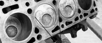
7. Measure the diameters of the cylinder in two perpendicular planes (Fig. 7) (B - along, A - across the cylinder block) and in four zones (1, 2, 3 and 4).
For this you need a special device - a bore gauge.
The nominal size of the cylinder (see table), ovality and taper should not exceed 0.05 mm.
If the maximum wear value is more than 0.15 mm or the out-of-roundness exceeds the specified value, bore the cylinders to the nearest piston repair size, leaving an allowance of 0.03 mm for the diameter for honing.
Then hone the cylinders, maintaining such a diameter that when installing the piston, the calculated gap between it and the cylinder is 0.025–0.045 mm.
Carry out troubleshooting, boring and honing of the block in workshops with special equipment.
Nominal sizes of cylinders and pistons
8. Check the deviation from the flatness of the surface of the connector of the block with the cylinder head.
Place a caliper (or ruler) on the plane:
– in longitudinal and transverse directions;
– along the diagonals of the plane.
In each position, use a flat feeler gauge to determine the gap between the ruler and the plane.
This is a deviation from the plane.
If the deviation exceeds 0.1 mm, replace the unit.
| Class | Diameter, mm | |
| cylinder | piston | |
| A | 82,00-82,01 | 81,965-81,975 |
| IN | 82,01-82,02 | 81,985-81,995 |
| C | 82,02-82,03 | 82,005-82,015 |
| D | 82,03-82,04 | — |
| E | 82,04-82,05 | — |
9. Check the clearances between the pistons and cylinders.
The clearance is defined as the difference between the measured diameters of the piston and cylinder.
The nominal gap is 0.025–0.045 mm, the maximum permissible is 0.15 mm.
If the gap does not exceed 0.15 mm, you can select pistons from subsequent classes so that the gap is as close as possible to the nominal one.
If the gap exceeds 0.15 mm, bore the cylinders and install pistons of the appropriate repair size. Measure the piston diameter at a distance of 10 mm from the bottom edge of the skirt in a plane perpendicular to the piston pin.
10. When replacing parts of the connecting rod and piston group, it is necessary to select pistons to cylinders by class and one group by weight, as well as piston pins to pistons by class and connecting rods by weight.
To select pistons for cylinders, calculate the gap between them.
For the convenience of selecting pistons for cylinders, they are divided depending on their diameters into five classes every 0.01 mm: A, B, C, D, E (table).
Spare parts are supplied with pistons of nominal sizes of three classes: A, C, E and two repair sizes (1st repair size - increased by 0.4 mm, 2nd - by 0.8 mm).
By weight, the pistons are divided into three groups: normal, increased by 5 g and decreased by 5 g.
The engine must have pistons of the same group installed.
For repair size pistons, spare parts are supplied with repair size rings increased by 0.4 and 0.8 mm. On the rings of the 1st repair size the number “40” is stamped, on the 2nd – “80”.
11. Cylinder class designations are stamped on the bottom plane of the block (the mating surface under the oil sump) opposite each cylinder.
12. The following data is stamped on the piston bottom:
1 – piston diameter class;
2 – arrow showing the direction of installation of the piston;
3 – engine model.
13. Replace pins with cracks.
The finger should easily enter the piston using the force of the thumb.
Insert your finger into the piston.
If play is felt when rocking the finger, replace the piston. When replacing a piston, select a pin according to its class.
14. Replace broken rings and oil ring expander
13. Replace pins with cracks. The finger should easily enter the piston using the force of the thumb.
Insert your finger into the piston.
If play is felt when rocking the finger, replace the piston.
When replacing a piston, select a pin according to its class.
14. Replace broken rings and oil ring expander.
15. Replace broken or cracked circlips that retain the piston pin.
The ends of the retaining rings must be in the same plane.
Replace bent rings.
16. Replace bent connecting rods.
Replace the connecting rod if there are burrs and deep scratches in the bushing 1 of the upper head.
Replace the connecting rod if, upon disassembling the engine, it is discovered that the connecting rod bearings have rotated in the connecting rod.
Warning Connecting rods are processed together with the caps, so they cannot be disassembled.
17. Insert a pin into the upper end of the connecting rod.
If play is felt when rocking the pin, replace the connecting rod.
Connecting rods assembled with covers are divided into classes based on the weight of the upper and lower heads.
18. Connecting rods of the same class must be installed in the engine.
The connecting rod markings are located on the lower head and the connecting rod cover.
19. If there are deep marks, scratches, nicks on the surfaces on which the oil seals operate, the crankshaft must be replaced.
20. Measure the crankshaft main and connecting rod journals.
Nominal diameters of crankshaft journals, mm:
– connecting rods – 47.830–47.850. If the wear or out-of-roundness of the journals exceeds 0.03 mm, they need to be ground to the nearest repair size.
There are four repair sizes with a reduction in the diameter of the journals, mm:
21. If there are minor scuffs, marks, or scratches on the main and connecting rod journals 1, you need to grind them to the nearest repair size.
It is recommended to carry out this work in a specialized workshop.
After grinding, polish the journals and blunt the sharp edges of the chamfers of the oil channels 2 with an abrasive cone.
Wash the crankshaft and blow out the oil passages with compressed air.
The ovality and taper of all journals after grinding should not exceed 0.005 mm.
After grinding the journals, install inserts of repair sizes.
22. If there are burrs, marks or peeling on the working surfaces of the thrust half-rings, replace the half-rings. It is prohibited to carry out any adjustment work on the half rings.
Engine cylinder piston clearance 21126
Good night,
I continue to drive and periodically repair cars
I have new questions and am still looking for solutions
so how it all began
I’m standing in a traffic jam under the bridge, the pace jumped sharply to 110, the computer beeped
I jumped out, topped up the antifreeze and slowly crawled to the side of the road. Well, slowly. Then I add water from the washer. There was a slight knocking sound while driving.
I flew home and started looking - the plug in the timing belt area had rotted. changed it, filled it with new antifreeze, installed a new belt and adjusted the valves. I drove 250 km, the knocking intensified. It became a point to get on the track.
Today I took off my head - there were bulges on 2 glasses under the adjustable washers that are on the valves. Several oil scraper rings burned out, half of the valves are dangling like a bucket in an ice hole. Well, I understand that, there is wear and tear, overheating.
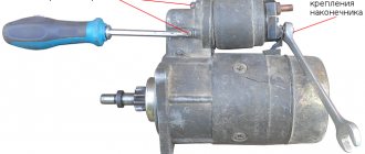
I take a screwdriver and put on a brush (not a toilet brush)
I dip it in a bowl of solarium and polish the head and piston, everything I can get my hands on. When it started to shine, I started looking at the gaps.
The piston costs are 3 pcs gr B2, 1 pc gr C2. I drove them and in the extreme positions between the piston and the cylinder (the average for all) the gap is 0.35mm
their arms sway slightly.
provided that the piston should be held lightly without rings in the cylinder and lower smoothly in the oil.
I felt the cylinders, did not see any signs of wear, I didn’t even feel the steps from the top ring, and I didn’t even notice the ellipse with my finger.
The actual dilemma is which pistons to install?
What confuses me is that they are different groups.
If C2 is already standing and dangling, then look for D? and the neighbors will wedge? and what about the rings
? Manle and STK can’t be found yet, the original VAZ is expensive, they offer SM for 800 rubles
and what’s also interesting is that I’m satisfied with the way it pulls the load. The piston is not completely killed yet, it will roll off 20-30 thousand calmly. (Comparing with 2107, it didn’t pull under the final at all and there was just a column of smoke flying into the gas outlet)
Yandex rules
Block cylinders Pistons A 82.00-82.01 81.965-81.975 B 82.01-82.02 81.975-81.985 C 82.02-82.03 81.985-81.995 D 82.03-82.04 81.995-82.005 E 82, 04-82.05 82.005-82.015
Classes of piston pins by outer diameter and pin hole diameter
Table 8.1.31.2 Class Marking color Diameter, mm Pin Piston Connecting rod 1 Blue 21,970-21,974 21,978-21,982 21,978-21,982 2 Green 21,974-21,978 21,982-21,986 21,982-21,986 3 Red 21,978-21,982 21,986-21,990 21,986-21,990
In total, by working with the calculator, it turned out that you need E3 and then it should hang out!
This is the only thing that can help - Repair pistons come in two sizes. Pistons of nominal size are not marked. Pistons of the first repair size are manufactured with a diameter increased by 0.4 mm and are marked with the symbol “►”. Pistons of the second repair size have a diameter increased by 0.8 mm and are marked with the symbol “■”
There is still some confusion regarding repair pistons.
I have a total of 0.35 minus 0.035 - a total of 0.315 is normal. and repair pistons from 0.4 go - next. 85 microns extra. DON'T FUCK! then install E3 and not worry?
through complex mathematical calculations
I came to the conclusion that the difference between classes B and E is only 0.03 (and it should be 0.3), that is, there is almost none. Only boring it to repair size will help. Well, I won’t sharpen it, I don’t have money for that.
How to determine their real wear - can you advise?
I'll try to see the locks on the top tomorrow - max wear is 1mm
I wonder why there is no wear visible on the cylinders, but the pistons dangle like something in an ice hole. Are the pistons really that worn out? or stuck in whatever they came across?
I’m sitting and thinking, maybe I should try class A for the first repair? Tomorrow I'll measure only the cylinders again. Well, a C class piston cannot dangle SO at any height in an unworn cylinder - only if the cylinder has been sharpened.
Then why is it worth C and not 1st repair?
Maybe I missed something somewhere, but how many cars passed. It is necessary to measure the cylinders with a bore gauge and, based on the obtained dimensions, decide whether to sharpen or simply change the pistons. But it’s not realistic to detect ellipse and wear with your finger.
Replacement cost
Here are approximate prices for replacing piston rings in services:
- domestically produced passenger cars - from 7-8 thousand rubles;
- Japanese foreign cars in sedan, hatchback, station wagon bodies - from 10 thousand rubles;
- jeeps, crossovers, minibuses - from 15 thousand rubles.
And the price for replacing a piston is usually high. This is explained by the fact that the procedure is included in the list of engine overhauls. Therefore, the cost is appropriate - from 20 to 40 thousand rubles.
Repairing engine 21126 VAZ 2170 Priora after timing belt break
Today we brought one of the old clients to the Priora, as it turned out, the jammed pump broke the belt and, as a result, the valves were bent.
But progress at AvtoVAZ does not stand still, and if on the engines of the tenth family the valves were simply bent, then on the Priora 126s the connecting rods also lose alignment and, if they are not changed, there is a high probability that the engine will begin to eat oil and, accordingly, your money. Glory to the designers of AvtoVAZ!
But every cloud has a silver lining, there are sets of pistons for 126 engines with grooves that do not bend the valves. In this article we will describe the procedure for repairing the cylinder head after a broken timing belt, as well as replacing the piston. Removing and installing the timing belt is described in this article, so we will not dwell on it in detail.
To perform this procedure, torque wrenches are required!
I use two keys: 28-210 Nm with a 1/2 square and 5-25 Nm with a 1/4 square.
How to choose new pistons when purchasing?
There is a wide range of these products on the domestic market. It is usually difficult to choose between pistons manufacturing technology - forged or cast. The first varieties are much more expensive. The second ones are more common. Before making a choice, you need to understand whether the car requires an increase in standard power. If yes, then definitely give preference to forged analogues.
Pistons are regularly subjected to high loads, so the performance of the internal combustion engine directly depends on their quality. An important parameter is also the weight of the product. Manufacturers try to make them light, but at the same time durable.
When choosing, it is recommended to pay attention to the German brands Kolbenschmidt, Mahle, Prima . The Russian Motordetal-Kostroma and STK have proven themselves to be quite good at producing such products.
Let's start to disassemble
First, drain the oil and antifreeze. We remove the protective cover, the air filter with pipes, disconnect the ignition coil connectors, the throttle cable and the throttle assembly.
We remove the thermostat housing and simultaneously disconnect all the available connectors and pipes. We remove all the wiring that was in our way towards the battery.
We remove the generator. We unscrew the eight thirteen nuts holding the intake manifold and remove it. We unscrew all the bolts securing the valve cover, as well as the side engine support.
Unscrew the eight nuts and remove the exhaust manifold.
Remove the timing belt, camshaft pulleys and pump.
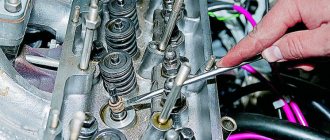
In three passes, so as not to deform the part, we first loosen and then unscrew twenty bolts of the camshaft bearing housing, the head is eight.
Be sure to follow the sequence shown in the photo.
Remove the bearing housing. We remove the camshafts; there is a distinctive lip on the intake camshaft.
Also, in several passes, we first loosen and then unscrew the ten cylinder head mounting bolts.
Be sure to follow the sequence shown in the photo.
Remove the cylinder head. All sixteen valves are replaced.
Cylinder head repair
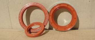
We mark all hydraulic compensators with numbers using an ordinary clerical touch and put them away. An ordinary magnet will help you pull them out. We dry out the valves and remove the oil seals (valve seals), the valves into scrap metal, the oil seals into the trash. We clean all channels. We take the head for grinding, just in case. After washing it again with kerosene after sanding and blowing it with air, we begin to assemble it.
We arrange the recently purchased valves in the sequence in which they will be located in the cylinder head and begin to grind in one by one. Lubricate the valve stem with clean oil and apply lapping paste to the edge.
We insert the valve into place and put a valve grinding tool on the valve stem. The stores sell a device for manual lapping, but since this is the twenty-first century, we are mechanizing the process. We take the old valve and cut off the rod from it, select a rubber tube for it of such a diameter that it fits tightly. The rod is in a reversible drill, one end of the tube is on it, the other is on the valve being ground in. At low speeds we begin to grind the valve, constantly change the direction of rotation and periodically press it to the seat or weaken the force. On average, the valve takes about twenty seconds. We take it out and wipe it.
The valve is considered ground in if a uniform gray strip of at least 1.5 mm wide appears on the chamfer.
The same stripe should appear on the valve seat.
Compliance standards
In its initial state, the cylinder fully corresponds to its name; it is a geometric figure with a constant diameter along the entire height and a circle in any section perpendicular to the axis. However, the piston has a much more complex shape, and it also has heat-setting inserts, as a result of which it expands unevenly during operation.
To assess the state of the gap, the difference between the diameters of the piston in the skirt area and the cylinder in its middle part is selected.
Formally, it is generally accepted that the thermal gap should be approximately 3 to 5 hundredths of a millimeter in diameter for new parts, and its maximum value as a result of wear should not exceed 15 hundredths, that is, 0.15 mm.
Of course, these are some average values; there are a great variety of engines and they differ both in different approaches to design and in the geometric dimensions of parts, depending on the working volume.
Let's move on to the cylinder block
We remove the pallet. Rotating the crankshaft as it is convenient for us, unscrew two bolts on each connecting rod cap. We use a TORX E10 head for this.
We take out the pistons along with the connecting rods. To do this, use the wooden handle of a hammer to press the connecting rod from below and lightly tap it to knock it up. We remove the old liners and buy new ones of the same size according to the markings on them. Here is another stone in AvtoVAZ’s garden, the owner has never climbed into the car from the interior or into the engine, but three pistons were of group “B” and one was “C”. It turns out that at the factory they re-sharpened one cylinder a little and simply put an enlarged piston there, no words. There are no options, we take group “C”, don’t sharpen the engine because of this. We will not touch the main liners either.
We buy a new piston group that does not bend the valves, connecting rods and connecting rod bearings.
Eliminating longitudinal play of the crankshaft
It was noticed on this motor. To eliminate it, replace the thrust half-rings. Standard and repair sizes are available. We take the first repair size, if they are too tight we sand them down a little. We unscrew the middle main bearing and gently push it with a screwdriver and move the half rings. The mark on it is in the form of three serifs, shown below.
When the half ring comes out a little, turn the crankshaft, it will push it out. There are two types of half rings: white at the front and yellow at the rear; the grooves on them should point towards the crankshaft cheeks.
We install them as we removed the new half rings; if they go in with great effort, you can grind them a little on a small abrasive stone, but not from the side of the grooves. Checking the play.
We tighten the main bearing with a torque of 8 kgf*m.
Assembling the piston
There is an arrow stamped on the top of the piston; it should be directed towards the front of the engine. And there are marks on the connecting rod that should look the same way.
We insert one retaining ring into the groove on the piston. We insert the connecting rod into the piston and, having lubricated the connecting rod and the piston pin with oil, insert it into place. Insert the second retaining ring. Although this operation seems simple, it will take some pains. We inspect the assembled structure; all retaining rings must be clearly in their grooves, otherwise a ring that has jumped out while the engine is running can cause a lot of trouble.
After assembly, you need to break off the connecting rod bearing cap, since the connecting rod is made in one piece. It's like that on our cars. First, unscrew the bolts. We insert the connecting rod into the cleats at the level of the mark shown in the figure with the black arrow and lightly clamp it, then break it off with a slight movement of the hand. The first time is very scary. We put the cover in place and tighten the bolts so as not to mix it up in the future.
Checking the thermal gap in the piston rings
We lay out each set of rings for each cylinder.
In the future we will not change their places.
In turn, we insert each ring into its own cylinder and push it a little with the piston approximately to the middle.
We measure the gap with feeler gauges.
Nominal clearance: 0.25 - 0.45 mm.
The maximum clearance for all is 1 mm. But this already smacks of waste.
Installing new rings
First, install the oil scraper ring expansion spring, then the ring itself. The oil scraper ring lock should face the opposite direction of the spring lock. Then we install the lower compression ring and finally the upper compression ring.
The inscription “TOP” must be stamped on the rings; it must face up.
The rings in the piston grooves must rotate easily.
Causes of piston group wear
Constant operation of the machine inevitably leads to damage to the steam generator. Like any other element of the power unit, pistons wear out due to obsolescence or due to overheating caused by a disruption in the combustion process.
What causes piston crown wear?
Seizures on the piston bottom are formed due to clogging or deformation of the oil nozzle, installation of elements with different sizes, or a malfunction in the cooling system.
Pistons on used cars often show impact marks. They are caused by an overly large piston protrusion or improper adjustment of the end side of the cylinder head. This also happens due to engine oil deposits on the head of the element, an unusually narrow gap in the valve drive and incorrect installation of the gas valve phases.
Damage is also determined by metal deposits on the elements. This happens when the injector is faulty - in this case, the injection quantity is determined incorrectly by the system. This will also indicate insufficient compression, late or early ignition.
If cracks are observed on the piston crown and in the combustion chamber cavity, this is evidence of a faulty injector or insufficient compression. This is also possible if the engine is not properly chipped, when they try to increase the power of the unit through modernization.
Causes of ring damage
As a rule, this happens due to erosion of the material in the ring area caused by improper installation, excess fuel in the combustion chamber, or violation of the thermal gap between the piston and its cylinder. The same thing happens with strong axial wear of the piston grooves and vibrations.
Another reason is radial wear associated with mixing. Any disturbance in the fuel combustion process, as well as insufficient compression pressure, lead to such a malfunction.
Axial wear is also possible as a result of simple contamination, when soot particles stick in the groove due to insufficient filtration. This could be sawdust, blast residue, or any other abrasion product.
Why is the piston skirt damaged?
Several reasons contribute to this - deformation of the connecting rod, crookedly installed cylinders, excessive play of the connecting rod bearing. In these cases, an asymmetrical, clearly visible spot forms on the skirt.
There may also be 45-degree burrs and other friction marks caused by an overly tight pin fit or an error in the installation of the hot-pressed connecting rod. The reason is also called a low compression percentage, misfires, and dilution of the oil with gasoline.
The main signs indicating resource depletion:
- blue exhaust color;
- active carbon deposits on spark plugs;
- drop in engine power;
- unstable operation of the unit at neutral speed - quickly determined by strong vibrations of the gearshift knob.
And, of course, the most important sign is increased engine oil consumption.