To ensure high compression in the engine, and this greatly affects its efficiency and other capabilities in terms of efficiency, ease of starting and specific consumption, the pistons must be installed in the cylinders with a minimum clearance. But it is impossible to reduce it to zero; due to different temperatures of the parts, the engine will jam.
Therefore, the gap is determined by calculation and strictly observed, and the necessary seal is achieved by using spring piston rings as a gas and oil seal.
What should be the thermal gap between the piston and cylinder?
Functional clearance requirements include:
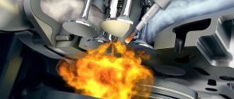
- Heat loss from the piston during fuel combustion. Otherwise, the piston will become unusable under the temperature of the combustion chamber.
- Possibility of compacting the area next to the pistons. The resulting pressure should equally push the rings towards the cylinder walls. To achieve such a touch, you need to set a suitable interval.
- Requirements for oil scraper discs, which are responsible for providing the required volume of lubricant. If you follow this principle, you can keep oil and fuel costs at production standards.
What's the result?
It must be admitted that keeping the middle-aged Shniva in good shape takes a lot of time and money. Even though I carry out many repairs myself, one kilometer costs more than five and a half rubles. Of course, life is not easy for our car, because it often has to drag a heavy trailer. I’m ready to assume that with normal, more gentle operation, its maintenance would cost 10–15 percent less. That is, the cost of repairs and spare parts would be 650–700 thousand rubles. It still turns out to be quite expensive. After all, today even for this money you can buy a new car.
Chevrolet Niva
- Manufacturer: GM-AVTOVAZ, Russia
- Year of release: 2013
- In operation "Behind the Wheel" - since May 2013
- Mileage at the time of report - 145,000 km
Why does the gap between the piston and cylinder change?
Machine developers want to ensure that the components of the motor function according to the mechanism of contacting liquids.
This is a method of lubricating the contacting sides, where, due to the strength of the oil coating or when the oil is injected under pressure, and the fixed costs, direct contact of the components does not occur in the event of overload.
In rare cases, this effect can be achieved. This depends on the following factors:
- Lack of oil, lubricant supply, as is allowed in the plain bearings of crankshafts or camshafts, is not carried out under pressure in the area between the piston and cylinder, and other lubrication methods rarely have a lasting effect; specialized oil nozzles function perfectly, but due to various circumstances they are not installed so often;
- A poorly executed or erased honing pattern on the cylinder wall serves to hold the oil shell and does not allow it to disappear entirely under the pressure of the piston rings;
- Incorrect temperature conditions can cause this interval to disappear, the oil ball to deplete and splinters to appear on the pistons and cylinders;
- Use of low quality oil fluid with violations of basic parameters.
Surprisingly, most often the cylinder coating becomes unusable, although it is usually made of steel, a solid steel block or a variety of dry and wet liners that are poured into the aluminum of the block.
If there is no liner, the wall of the aluminum cylinder undergoes special treatment, and a ball of dense, durable coating is applied to it.
This is due to the persistent pressure on the piston, which, in the presence of lubricant, practically does not remove metal from it during movement. But the cylinder is subjected to increased isolated pressure due to the small contact distance due to the careless functioning of the spring rings.
Of course, the piston also becomes unusable, even if this process does not develop so quickly. Such mutual wear of the contact surfaces, the distance gradually increases, and is also unequal.
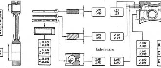
Assembly of connecting rod and piston group
To assemble the connecting rod with the piston, you need to match the piston pin to the bushings of the upper head of the connecting rod and the piston bosses. To connect to the connecting rod, the piston is heated in oil or in an electric heater to a temperature of 55 °C. In this case, the finger should enter smoothly into the hole of the heated piston boss using the force of the thumb of the right hand. In such a connection, after cooling the piston, the required interference of 0.0025 ... 0.0075 mm appears.
Then you need to check the serial numbers of the pistons and connecting rods. The connecting rod is secured in a vice, the piston is installed, and their connection is fixed with a finger. When assembling the piston with the connecting rod, it must be installed so that the mark on the piston bottom is directed towards the front of the engine. The boss stamped on the connecting rod for the left bank of cylinders should also be directed towards the front of the engine, i.e.
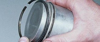
After connecting and checking the connecting rod-piston group, you should secure the pin in the piston bosses with retaining rings, then carefully wipe the piston rings selected along the grooves and fitted to the cylinders and install them on the pistons using a special device. The pistons and connecting rod assembly must be checked for weight.
- turn the engine block, install it vertically on the stand, with the front part up;
- sequentially, one after another, take the pistons and connecting rods assemblies;
- thoroughly wipe the bed under the liners in the lower head of the connecting rod with a napkin;
- unscrew the nuts and remove the connecting rod cover;
- install the connecting rod with the piston.
Then you need to check and blow out the hole in the lower head of the connecting rod, which serves to spray oil onto the cylinder walls, insert the liners into the connecting rod and into the cover, wipe the upper connecting rod liners and the piston with a napkin, install the rings on the piston, placing the internal groove upward, move the joints of the compression rings apart piston circumference by approximately 120°. After installation, separate the joints of the compression rings by 180°.
Next, wipe the cylinder liners of the block and the connecting rod journal with a napkin, lubricate the surface of the connecting rod bearing, piston, piston rings and cylinder liners with clean oil used for the engine, insert the piston with the connecting rod into the cylinder, pointing the mark on the bottom of the piston to the front of the engine using a special fixtures, bring the connecting rod bearings to the crankshaft journal, moving the piston along the cylinder using a wooden mandrel, lubricate the shaft journal with oil and tighten the lower head to it, remove the safety tips from the connecting rod bolts and replace the lower connecting rod cover, securing it with connecting rod nuts.
Before completing assembly, you need to check the total axial clearance between the ends of the connecting rods and the crankpin of the crankshaft using a feeler gauge and finally tighten the connecting rod bearing bolts with a torque wrench. After tightening each pair of connecting rod bearings, rotate the crankshaft. The rotation torque of the shaft with correctly selected radial clearances in the bearings should be no more than 100 Nm. Similar operations must be carried out when installing the remaining pistons with connecting rods into the cylinders.
- carbon deposits on the bottom and in the grooves under the rings;
- cracks and scratches on the walls;
- diameter wear;
- wear of grooves for piston rings;
- wear of the holes in the bosses.
Carbon deposits are removed from the bottom with a blunt metal scraper or a metal brush, having previously moistened the carbon deposits with kerosene.
Carbon deposits are removed from the grooves using a special device. The presence of cracks in the piston is determined by ear, for which the piston is taken by the head, and light blows are applied to the skirt with a metal object. A dull, rattling sound indicates the presence of cracks.
Pistons with large diameter wear, cracks and deep scratches must be replaced. Worn grooves for piston rings can be machined to accommodate the increased size of the rings in height on a lathe using a device that is a ring with an outer diameter equal to the internal centering belt of the piston.
The piston is placed on the ring installed in the machine chuck and secured with an eye bolt. The eye bolt is connected to the piston by means of a piston pin and passes through the machine spindle. On the reverse side the bolt is secured with a nut. The grooves on the piston should be machined taking into account the established repair dimensions of the piston rings.
Worn holes in the bosses are repaired by reaming them to fit the increased diameter of the piston pin using a sliding reamer with a guide shank. The use of short reamers is unacceptable, as this easily leads to a violation of the perpendicularity of the pin axis with the piston axis; therefore, after deployment, it is necessary to check the perpendicularity of the axes using a special device.
The piston is put on the finger of the device and moved close to the rack. In this case, the indicator pin attached to the rack comes into contact with the piston, and the indicator arrow will give a certain deflection. Having noticed the indicator readings, the piston is removed and put on the finger with the other side. The difference in indicator readings should not exceed 0.05 mm. Otherwise, the piston must be rejected.
This is interesting: Diagnostics of diesel engines - a computer scanner to help you
Compliance standards
In its initial position, the cylinder fully corresponds to its name; it is a geometric figure with a constant diameter throughout its entire height and girth in any section that runs transverse to the axis.
But, the piston has a somewhat complicated configuration; in addition, it contains heat-setting components, as a result of which they increase unequally during operation.
To assess the state of the gap, the difference in diameters of the piston in the area of the skirt and the cylinder in its central part is calculated.
According to established standards, the thermal gap should be approximately 0.03-0.05 mm in diameter for fresh spare parts, and its upper limit due to wear should not be greater than 0.15 mm.
cnitomis.ru
June 9th, 2013
The gaps between the ends of the valve stems and the rocker arms acting on them when the engine is warm should be within 0.25-0.30 millimeters. The gaps are adjusted by rotating the pusher rod 4 (see Fig. 9), which is screwed in or out of the rocker fork 8. For ease of grip with a wrench, part of the rod is made of square section.
The adjustment is made in the following order. Remove the cylinder head cover. Turn the engine crankshaft with a wrench using a bolt screwed into the front end of the crankshaft until the plunger of the injector pump of the first cylinder drops 6 mm from its top position, which corresponds to the piston being in. m.t. Check the size of the gaps with plate probes (a probe with a thickness of 0.25 mm should pass into the gap freely, and a probe with a thickness of 0.3 mm with great force or not at all). If the gaps deviate from normal, loosen the lock nut 7, set the required gap by rotating the rod and tighten the lock nut, after which the gaps are checked again. They also adjust the valve clearances of the remaining cylinders, each time turning the crankshaft before adjusting the valves of the next cylinder to a position where the piston of this cylinder is in position. m.t.
Rice. 11. Valve timing of YaAZ engines.
Valve timing. For the YaAZ-M204 and YaAZ-M206 engines, the required valve timing is obtained by choosing the correct size and height arrangement of the purge holes in the cylinder liners, through which air is supplied for purge, and the shape of the camshaft cams, which control the opening and closing of the exhaust valves. A circular diagram of the valve timing is shown in Fig. 11. The same diagram shows the start time and duration of fuel injection by the injector pump into the cylinder.
The order of operation of the cylinders of YaAZ engines. For YaAZ-M204 and YaAZ-M206 engines operating on a two-stroke cycle, all processes in the cylinders are completed in one revolution of the crankshaft. Therefore, the order of operation of their cylinders is determined by the sequence in which the pistons approach the engine. m.t. (or n.m.t.), i.e., depends on the location of the crankshaft cranks, with which the location of the camshaft cams is also coordinated.
Categories: Diesel cars |
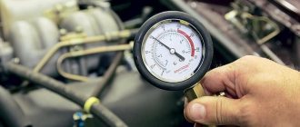
How to measure the clearance between the piston and cylinder
To determine the size of the gap, computing devices are used, such as a micrometer and a bore gauge; this combination of tools will help achieve high accuracy, which will make it possible to respond to a hundredth of a millimeter.
A micrometer measures the diameter of the piston in the area of its skirt, in the transverse direction relative to the pin. The micrometer rod is secured with a clamp, then the inside gauge is set to zero when it is fixed with its computing end on the micrometer rod.
After this procedure, the bore gauge converter will display discrepancies from the piston diameter in hundredths of a millimeter.
- The cylinder is measured in 3 planes, top, central and bottom, along the length of the piston moving area. Measurements are taken along the axis of the finger and in the transverse direction relative to the phalanx.
- Upon completion of the procedures, conclusions can be drawn about the condition of the cylinder after wear. The main thing you need is the presence of cone-shaped or ellipsoidal irregularities. The first is the deviation of the section from the circle towards the oval, and the second is the discrepancy in diameter on the vertical axis.
Defects of several hundredths indicate the impossibility of working with the rings and the need to repair the cylinders or change the block.
Causes of wear
Here are some of the signs of wear that you should look out for first:
- Increased fuel consumption;
- Significant oil loss (max-min level per thousand kilometers);
- Exhaust gases have a bluish tint;
- Engine compression is less than 9.
Unfortunately, if you notice all these signs in your car, then the engine can only be helped by replacing the VAZ 2101 piston. The most critical element in the engine piston group is the piston rings, which simultaneously perform several functions:
- Sealing the combustion chamber (prevents gases from entering the engine crankcase);
- Protecting the piston from overheating by transferring heat from its head to the cylinder, which is intensively washed with coolant;
- Uniform distribution of the oil film over the surface of the cylinder, while preventing oil from penetrating into the combustion chamber.
For optimal operation, the rings must fit evenly and tightly to the entire surface of the cylinder, however, over time, the geometry of the cylinder changes, the gaps in the piston grooves and at the joints of the rings increase, and their elasticity is impaired. As a result, the sealing is broken, gases penetrate into the engine crankcase, and increased wear of the entire piston group begins.
As wear increases, the amount of gases increases, crankcase ventilation cannot cope and the pressure in it increases significantly, which helps to squeeze out oil through the crankshaft seals, gaskets and distributor socket. This unpleasant situation can be corrected by replacing the piston rings on a VAZ 2101, especially since the cost of replacement is much lower than the cost of repairing the entire engine, since for this procedure we only need new rings and gaskets for the pan and cylinder head. Special tools include a piston ring crimper and a torque wrench, although you can do DIY repairs without them, after all, what difference does it make where your hands come from, as long as they are golden!
Instructions for removing and diagnosing the cylinder head
- First of all, you need to immobilize the vehicle. Wheel chocks are placed under the wheels, and the gearshift lever remains in first gear. Then you need to open the hood of the car and find the cylinder head.
- First, all components that prevent free access to the head are dismantled. This could be: an air purifier, a carburetor (or injector), and various kinds of cables, pedal drives and electrical converter wires. The spark plugs are removed from the cylinder head and, if necessary, the distributor is dismantled.
- Then the engine oil and coolant are drained. The timing cover is opened and the belt is removed. Then the nuts securing the cylinder head cover are unscrewed and removed together with the gasket. Before assembly, it is worth installing a new gasket.
- And the final step is to remove the cylinder head. The special fixing bolts are unscrewed and the head together with the gasket is dismantled. As a result, the entrance to the cylinder block opens.
Description of the motor device 21213
The basis of the VAZ 21213 engine includes:
- cast iron cylinder block (BC) 21213-1002011;
- block head 21213-100301*;
- crankshaft 21213-1005015;
- connecting rod and piston group 21213-10040*.
The main difference between the 21213 engine and its predecessors was the increased cylinder diameter - 82 mm versus 76 and 79 mm. The center-to-center distance of 95 mm remains the same, and allows the block to be bored to a diameter of 82.8 mm. The design of the water jacket has changed. The working volume has increased by 100 cm3, but the engine dimensions have remained the same.
To install the crankshaft in the BC there are 5 supports: one each on the front and rear walls, 3 more on the ebb. The crankshaft parameters provide a piston stroke of 80 mm. The crankshaft is cast from cast iron and consists of 4 connecting rods and 5 main journals. The connecting rod journals have oil channels. The necks are separated by cheeks with counterweights. In previous VAZ engines, balancing counterweights were found only in the outer and central cheeks. The axial movement of the shaft is limited by thrust half-rings.
The piston group for the 21213 engine was developed anew. Pistons 21213-1004015 are cast from aluminum and reduced to a single mass of 347 g. The piston class (A, B, C, D, E) is determined by the outer diameter in increments of 0.01 mm. The shape of the piston is conical in height and oval in cross section. The hole for the pin is 22 mm, offset by 1.2 mm from the piston axis. The finger is locked with rings. There are 3 rings installed on the piston skirt:
- upper compression barrel;
- medium oil scraper with expansion coil spring;
- lower compression scraper type.
The connecting rod 21213-1004045 is forged from steel and processed together with the cover. A steel-bronze bushing is pressed into the upper head of the connecting rod. To fasten the connecting rod, M9x1.0x56 bolts are used.
The aluminum BC head is designed for the VAZ 21213 engine and is designed for compression from 10 bar. Installing a head from other motors may cause it to break. Cast iron seats and guide bushings for 4 intake and 4 exhaust valves are pressed into the head. The valves operate from the camshaft cams. The gap between the valve stem and the cam is adjusted with a bolt.
Similar article 405 ZMZ engine, technical characteristics
timing belt
The camshaft 21213-1006010 is made of cast iron and rests on 5 journals. The jaws are bleached to increase wear resistance. Axial movement of the shaft is limited by a thrust flange.
The timing belt is driven by a double-row bush-roller chain. In addition to the camshaft, the chain drives the oil pump. The drive is regulated by a semi-automatic tensioner with a shoe and damper. To prevent the chain from falling off when removing the camshaft sprocket, a limiter is provided next to the crankshaft drive sprocket.
Systems
The power supply system in the Niva 21213 engine is a 21073 Solers carburetor. The carburetor unit is two-chamber, the throttle valves operate sequentially. When the first chamber is 2/3 open, the throttle of the second chamber is engaged. At idle, the economizer turns on. The carburetor device includes:
- float chamber;
- 2 dosing systems;
- crankcase gas suction system;
- heating the throttle zone of the first chamber;
- blocking the second camera;
- economizer;
- econostat;
- diaphragm accelerator pump.
The ignition system in the 21213 engine is non-contact. The system is controlled by a switch using distributor signals. In general, the system is classic, without any special features.
Cooling of the motor occurs according to a typical scheme: liquid circulates through the water jacket in the BC and the block head. The pressure is created by a centrifugal pump connected by a belt drive to the crankshaft and generator. The radiator fan impeller works on suction, so in winter the radiator has to be covered with cardboard.
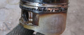
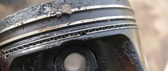
Photo of the ideal thermal gap between the piston and cylinder
What is it made from?
Let's consider the materials of the CPG parts. All materials for CPG must have high strength, excellent thermal conductivity, slightly expand when heated and have anti-friction properties. Have increased resistance to rust.
The sleeves are made of cast iron or special steel with additives so that the part can withstand high loads.
Pistons were initially made of cast iron, but with the development of technology, aluminum began to be produced. Modern engines use prefabricated steel pistons, especially diesel engines. In experimental engines, ceramic pistons are being tested, but so far in production, ceramics are used only as a coating on pistons.
Piston rings are made of high-strength gray cast iron with the addition of molybdenum, chromium, tungsten or nickel. Additives provide better “break-in” of parts, increasing their wear resistance and resistance to high heat.
The piston pins are made of alloy or carbon steel, carburized and hardened. If the file leaves scratches on the finger, these are defective (not hardened) fingers, they cannot be installed, this will lead to failure of the CPG.
To summarize, I’ll tell you which engines have a CPG. This group is present on all units operating on the principle of internal combustion. Regardless of whether the unit is diesel, petrol or gas. Due to their convenience and relative simplicity of execution, reliability and durability, as well as safety for humans (except for environmental friendliness), cylinder-piston gas engines are widely used all over the world, even in mowers and chainsaws. Electric motors do not have CPGs; they operate on a different principle.