The unit that prepares the air-fuel mixture and supplies it to the power unit is the most important component of all cars of the classic series (only export models were equipped with injection devices) and some other models produced at the Volzhsky plant. Despite the fact that modern vehicles are no longer equipped with carburetor engines, a large number of cars with such engines still faithfully serve their owners. Therefore, it is important to know what the VAZ 2107 carburetor is, to have an understanding of its design and maintenance.
The article was written thanks to the website “Your Home Design” - this is an information portal about the interior design of apartments and houses. Landscape design, dachas: new items, photos, videos, options for the ideal combination and recommendations from professionals. As well as handmade crafts and everything connected with them.
Main types of DAAZ carburetors
Of course, carburetor feed mixture supply systems are considered obsolete today. However, according to a number of criteria they are superior to injection designs. A small number of electronic components increases the reliability of the unit and ensures ease of repair work. In addition, carburetor engines do not have high requirements for fuel quality.
Carburetors can be of three types.
- Bubbler. These devices are no longer used. The principle of operation of the unit was to prepare and supply a mixture of air with the vapor fraction of the fuel.
- Membrane-needle-shaped. The assembly consists of several compartments that separate the membranes. They are connected to each other by a rod ending in a needle. This device locks the valve seat through which the fuel mixture is supplied.
- Float This type is most widely used due to its reliability, good quality of the fuel-air mixture and ease of setup. Structurally, it consists of a float-type chamber necessary for the influx of fuel and a compartment where it is mixed with oxygen.
Ozone carburetor repair and adjustment
Pavel [therock9618]
24.03.2021,
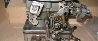
Hello! It's time to get acquainted with the second generation of DAAZ carburetors - "Ozone", which is quite often found on VAZ cars of the classic model. In the last article, I explained the repair and adjustment of the Weber carburetor and I want to say that Ozone is almost the same Weber, with the exception of some innovations, namely: a pneumatic drive of the secondary chamber throttle valve and a modified idle system. Go!
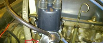
When you are convinced that the carburetor needs to be completely cleaned, it should be removed from the car. To do this, first remove the air filter housing, the hose going to the vacuum brake booster (if there is one), the vacuum ignition timing regulator drive hose, the crankcase ventilation hose and the fuel hose. If you have gas equipment, there is a special spacer for Ozone with throttle valves and connections for gas pipes - disconnect them.
Also, if you have EPHH (forced idle economizer), remove the terminal from the valve. Disconnect the choke cable by loosening the mounting screw and the rod end locking screw. The throttle valve drive is removed using a slotted screwdriver - you need to pry and remove the rod from the drive lever hinge.
Using a 13 mm spanner, unscrew the 4 nuts securing the carburetor to the intake manifold. If you use a regular open-end wrench, you will not be able to unscrew the nut under the accelerator pump, since the body of the wrench will interfere with it, so use a spanner. If you don’t have one at hand, you will have to remove the accelerator pump cover by unscrewing the 4 bolts with a Phillips screwdriver.
Having removed the carburetor from the car, we proceed to its complete disassembly. First, remove the cover by unscrewing 5 screws with a Phillips screwdriver and removing the telescopic rod. To do this, squeeze the rod and remove it from the groove of the three-arm lever.
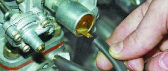
Using a thin nail, carefully knock out the float axis, remove the float, along with the needle and carburetor cover gasket. Check the float for leaks by lowering it into a container of gasoline. If it sinks, replace it, as the fuel level will be incorrect and the engine will begin to work poorly, as it will begin to “flood”.
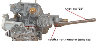
Using a 10mm wrench, unscrew the needle valve body - there is an O-ring on it. Using a 19mm wrench, unscrew the fuel filter plug and remove the filter mesh. Let's disassemble the starting device. Unscrew the 3 bolts securing the starter cover and remove it along with the diaphragm and return spring. Then unscrew the 2 bolts of the starter housing and remove it with the sealing ring of the vacuum supply channel.
In order not to get confused in the future by disassembling everything, let's immediately assemble and prepare the carburetor cover for installation. Using a carburetor cleaner, thoroughly wash the cover and blow with compressed air, remembering to blow through all channels. I recommend replacing the fuel filter mesh with a new one, since the quality of the fuel leaves much to be desired and requires high-quality fine cleaning. Screw on the filter plug. Screw the needle valve body with the O-ring and install a new gasket.
Reinstall the needle and float by hammering the axle. To check the tightness of the needle valve, create a vacuum using your mouth on the fuel supply fitting. The float should be raised as high as possible. A normally closed valve will not allow vacuum to pass through. If the needle is leaking, replace it.
Position the lid vertically and using a 6-7 mm drill, measure the distance from the float to the lid. If it is more or less than required, correct it by bending the float bracket. Thus, we achieve a failed fuel level. If there is a lot of it or, on the contrary, not enough, the engine may work unstably and be difficult to start.
It is also a good idea to check the full stroke of the float. To do this, place the lid in a vertical position and move the float away from it as far as possible. This distance should be 15 mm.
Inspect the trigger diaphragm for cracks. A damaged diaphragm should be replaced. In any case, I advise that when completely disassembling the carburetor, replace all gaskets, diaphragms and o-rings. Lightly sand the starter cover with fine sandpaper placed on a flat surface to achieve a flat surface of the cover and eliminate air leaks. Assemble the starter, but do not screw it to the carburetor yet. Pull the diaphragm rod out as far as possible and, using your mouth, draw air toward you through the hole in the trigger body. After this, release the rod. With a sealed diaphragm and a flat lid, the rod should remain extended, and when you remove the vacuum with your mouth, the rod will return back under the influence of the spring. Now screw the starter housing to the carburetor. The cover is finished and ready to install.
Let's move on to the body. First, remove the bottom cover by unscrewing the 2 fastening bolts from below and disconnecting the end of the pneumatic actuator rod, by removing the lock washer from the end of the rod, unscrew the 2 bolts securing the pneumatic actuator housing and remove the pneumatic actuator itself.
Checking the pneumatic drive. To check, squeeze the stem and draw air through your mouth through the hole in the body. Just like with the starter, when released the rod should remain in the retracted position, and then when you stop drawing air, the rod will return. Otherwise, you need to replace the diaphragm and, just in case, sand the cover with sandpaper. The pneumatic drive is disassembled by unscrewing 3 screws in the cover. Inside there is a spring and a diaphragm with a rod.
In the housing you need to unscrew 2 fuel, 2 air jets, the jet together with the accelerator pump nozzle, remove the emulsion tubes and diffusers. To remove the emulsion tube, carefully drive a drill of a suitable diameter or self-tapping screw into it and remove it. The diffusers are lifted upwards by slightly prying them with a screwdriver or pliers. The main thing is not to confuse the jet ratings when assembling. Later I will attach a photo with a table of jets. The jets themselves are unscrewed with a slotted screwdriver.
From the carburetor body on the accelerator pump side, unscrew the idle air system nozzle, which is pressed with a holder (plug) under a slotted screwdriver or a solenoid valve, if you have an EPHH. The valve is unscrewed with a 13 key.
On the back of the housing, unscrew the plug along with the nozzle for the secondary chamber transition system. The accelerator pump cover is secured with 4 screws. Inside is a diaphragm with a return spring. There is a cap screw on top, under which there is a bypass jet - you only need to unscrew the cap screw. Now the carburetor body needs to be washed, blown and the flange flatness checked. I have already said more than once that the crooked flange is a sore spot of the carburetor, since the wall is very thin, and when tightening the nuts securing the carburetor to the manifold, they are very overzealous and simply bend the flange by tightening it too hard. This is not due to temperature changes, but rather due to strong puffing. To check, you will need glass or a straight metal ruler. Place it on the flange and look at the light. In 99% of cases, a crooked flange and additional gaskets will no longer help, and tightness in this place is very important, since there is an idle passage between the body and the bottom cover.
If the curvature is very slight, you can carefully sand the plane, first removing the protruding tubes from it so as not to spoil them, because fuel flows through them. Do not be afraid that after grinding the flange wall will be thin, the mixture formation will not be the same, etc. - this is not true! =) But yes, the flange will be thinner, but now you know that you can’t overtighten the nuts, so don’t worry. If you still don’t want to use this method, then level it using a press. By the way, this method is the only one in the case when the plane is too curved. The carburetor body at the flange should be heated well with a torch so that the metal yields better and then placed under a press or homemade cleats.
Let's return to the components of the case. Check each jet to ensure it is rated using a suitable drill bit. Check all jets and tubes for clearance so that they are not clogged! Screw back the jets and sprayer. The main thing is not to confuse them! Jets should be selected in accordance with the factory table. On the body there is a marking of the carburetor model, according to which you find your model in the table and select the jets. Their number can be seen under a magnifying glass. But usually, what jets you should pay attention to are the fuel, air and idle jets. Basically, they install idle jet 50, fuel jets 112 (primary chamber) and 150 (secondary), air jets 170 (primary) and 170 (secondary).
Also wash, blow out the emulsion tubes and check that the channels are clean. Diffusers have channels that spray the fuel mixture into the cylinders - they need to be cleaned. It is also important to check the tightness of the diffusers to the channels in the housing. Sand the surface of the diffusers using sandpaper for prevention. The pressing force of the diffuser is provided by a wire spring on the reverse side. You can pull it out and try to bend it. Over time, the spring gets tired and bending is not enough, so you can gently tap the sides of the diffusers with a hammer to flatten them a little. This will help the diffusers fit tightly, the main thing is not to overdo it.
All that remains is to screw in the jets and put back the emulsion tubes and diffusers. Check that the secondary chamber adapter nozzle plug is screwed in all the way. Do the same with the idle jet plug. If you have an EPHH valve instead of a plug, then very carefully tighten it with a 13mm wrench, otherwise it will not work properly.
Inspect the accelerator diaphragm for cracks and replace if necessary. The accelerator pump cover is sanded with sandpaper and when screwing it on, I advise you to keep the diaphragm drive lever raised up. With this action, maximum filling of the accelerator pump is achieved.
We're done with the body for now. The bottom cover consists of 2 axes with throttle valves of the primary and secondary chambers, damper drive levers, idle channels and idle speed adjustment screws. Carefully shake both throttle valves and check for play; if there is any, tighten the 2 bolts securing the valve to the axle.
To check the damper drive mechanism, twist the levers of the primary and secondary chambers, opening them to the maximum position. And remember, since the secondary chamber has a pneumatic drive, the secondary chamber damper lever will open only when the primary chamber damper is open at least 50% (plus or minus), since when the primary chamber damper is closed, its lever blocks the secondary damper lever.
When rotating the damper drive levers, they should open without effort and clearly return to their original position under the influence of springs. If you feel a slight jamming, fill the levers with WD-40 and rotate them to open and close, possibly dirt has got there, and then blow with air. Otherwise, you will have to disassemble the levers and clean everything manually. The main thing is to collect everything the same way it was. To do this, use the photo that I will attach below. If necessary, after disassembling the damper drive mechanism, you can remove the axles and clean them together with the dampers. But the axles very rarely turn sour, and usually it is enough to clean the valves without disassembling anything.
On the side of the bottom cover there are 2 idle speed adjustment screws: the large one is the quality screw, and the smaller one is the quantity screw. You need to unscrew them and check the condition of the O-rings - they should be intact and elastic. But it's better to replace it right away.
Inside the channel where the quantity screw is screwed in, there is a sprayer. On older carburetors, it is a wide double ring with holes in a circle, and on younger ones it is an ordinary ring. A half-ring sprayer is much more convenient and reliable, since it does not have such thin holes that clog very quickly.
The sprayer itself is pressed inside, and to remove it you will need a special device that you can make yourself.
Or you will have to clean it on the spot with a needle, soak it in a cleaning agent for a long time, which is very inconvenient, especially with the sprayer of old releases - there are too many holes and each one needs to be cleaned. Sometimes you can’t get to it with a needle, and then use one short strand of stranded wire.
The body has been completely disassembled and is now ready for washing and cleaning. I advise you to pay attention to its flatness on both sides, since if the fastening to the manifold is tightly tightened, the bottom cover will also “lead.” Reassemble everything in reverse order. Don't forget to also clean the idle speed adjustment screws and passages. I would like to draw your attention to the fact that, unlike Weber, Ozone has both valves closed at idle, and under the primary chamber valve there is an idle hole that supplies fuel to the engine. It must be clean!
After assembling the bottom cover, you should adjust the position of the flaps. Point the lid to the light and look at the flaps. They should not allow light to pass through them. But at the same time I want to pay attention to how they lie. At each damper, a drive tab extends from the side of the carburetor, which rests on the screw. By rotating it, you can adjust the stop or, in other words, the clearance of the dampers.
By tightening the stop screw of each shutter little by little, find the position when it barely begins to let in light, and then turn the screw little by little until this gap disappears. This is done so that the damper rests clearly against the adjusting screw, and not against the wall of the channel, otherwise over time, when you press the gas, a hole will form in this place, which will allow excess air to pass through when the damper is normally closed.
This completes the cleaning and preparation of carburetor parts. Let's move on to assembly and configuration. Screw the bottom cover to the body with two screws and install new gaskets between them. Let me remind you that there is one thermal insulation pad and one cardboard pad on each side.
Let's start setting up the accelerator pump. Pour gasoline into the float chamber in accordance with the regulated fuel level. The level should be in the middle of the float chamber casting.
By turning the primary chamber flap drive lever, on the reverse side of the axis, the protrusion runs onto the accelerator pump rod and compresses the diaphragm, supplying a large portion of gasoline under pressure into the engine through the nozzle nozzle. First, the diaphragm needs to fill the cavity, since there is no fuel in it. Then the sprayer will start spraying. At this time, pay attention to the stream from the sprayer - it should be uniform and without smudges. If there is a discrepancy, clean the nozzle of the sprayer again with a thin strand of wire and blow it with air. Also, the spray jet should “hit” directly on the collector, that is, not on the diffuser, not on the chamber wall, not on the damper, but precisely on the collector. If the stream “hits” past, you can carefully bend the spout and check everything again until you achieve what I said above.
Now let's check the performance of the accelerator pump. Pour gasoline into the float chamber at the correct level, place the carburetor over a clean container and turn the throttle lever, give 10 injections with the accelerator pump. Draw gasoline from this container into a 10 cc syringe. With normal accelerator pump performance, you should get 7-8 cubic meters of gasoline. If there is a discrepancy with the specified volume, and also if the accelerator pump does not supply fuel at all or supplies it very poorly, check the discharge valve located in the spray nozzle. If the ball “sours,” the pump may not work at all. Everything can be solved by soaking in a cleanser and blowing with air. If the valve is working properly, you can hear the ball dangling if you shake it.
Also check the supply channels inside the pump - unscrew the accelerator pump cap, pour gasoline into the float chamber and turn the throttle lever. There should be visible streams of fuel with a characteristic bubbling sound coming through the bypass holes. If necessary, clean and blow out. Clean the accelerator pump bypass jet with carb cleaner by unscrewing the plug screw above the pump housing.
The body is ready. Screw on the carburetor cover, tightening the bolts crosswise to evenly distribute the gasket. I don’t see the point in pulling too hard, since after installing the carburetor on the car, you will check the fuel level in the float chamber and for this you will need to remove the cover again. Reinstall the telescopic rod. On Ozone carburetors there is often a telescopic rod or a closed-type “telescope”. This type of traction is unreliable, since dirt gets inside the moving elements and they stop working. Hence the poor start of the engine and it didn’t last long the first time. I advise you to install an open telescope to forget about this problem.
Let's set up the launcher. The principle of its operation is that you pull out the “choke”, which is connected by a cable to the air damper lever, which blocks the air channel of the primary chamber. When the engine is rotated by the starter, the engine discharge affects the starter diaphragm, which, through a rod, simultaneously opens the air and throttle valves of the primary chamber to the desired angle, delivering a rich mixture to the engine, which is important during cold starts. Therefore, with the choke extended and the engine running, the speed is about 3 thousand.
Adjusting the starting device consists of setting the required starting gaps of the dampers. The air damper opens at start-up by 5-5.5 mm, and the throttle by 0.7-0.9 mm. You will need one drill of the appropriate diameter for each flap. To check the current starting clearances, you need to simulate a manual start. To do this, first press the air damper drive lever so that it completely blocks the primary chamber channel, and then press the trigger rod. Now you can see both gaps.
The throttle clearance of the primary chamber is adjusted by bending the rod with pliers - the main thing is not to overdo it. We bent the rod, simulated the starting gaps, checked it with a drill, if it doesn’t match, we bent it again and checked it.
To adjust the air damper gap, in the center of the starter cover, there is a plug for a slotted screwdriver - unscrew it. There is also an adjusting screw inside for the slot, which, when rotated, adjusts the air damper clearance. Rotate it just during the launch simulation to make it easier to monitor changes.
The carburetor is ready to be installed on the car. Replace the gasket between the carburetor and the intake manifold and install the carb in the reverse order of removal. After installation, check that when the choke is pulled out, the air damper completely blocks the primary chamber channel. Also check that when you press the gas pedal all the way, the primary chamber damper is completely open.
Using the manual fuel pump drive, pump fuel into the carburetor. Depending on the pump's performance, I can't say exactly how much you need to pump. I think intensive pumping for one minute should be enough. Remove the carburetor cap and check the fuel level. Since you have already adjusted the correct clearance and float stroke when cleaning the carburetor, now you are checking for correct operation. In theory, the level should be normal, if not, correct it by bending the float bracket with the familiar way. Screw the cap on and this time you can tighten it.
Everything is ready for the first start and idle settings. Make sure that the ignition is working properly and is set correctly, there are good spark plugs with the required gap, and the fuel pump has good performance and its rod output is adjusted. I will devote a separate article to this procedure, but now let’s proceed to setting the idle speed.
If your quantity and quality adjusting screws are not tightened, tighten them all the way. Then unscrew the quantity screw by 1 full turn, and the quality screw by 2. Start the engine. If the engine does not start, unscrew each adjusting screw one more turn.
Your task is to start the engine. Even if it works unstably or at too high speeds, the main thing is to start it and warm it up, since the idle speed needs to be adjusted only when the engine is warm.
Now a little theory. Imagine 2 channels: air and fuel, which converge into one common channel, which exits under the throttle valve of the primary chamber. On each individual channel there is a screw: the amount of mixture in the fuel channel and the mixture quality screw in the air channel. Each screw changes the size of its channel, so when tightened, the patency of the channel becomes lower, and when unscrewed, it is correspondingly higher. It turns out that using screws, you manually adjust the idle mixture.
Once the engine has warmed up, you can begin tuning. To monitor the speed, use the standard tachometer in the dashboard or connected to the ignition coil. We carry out the adjustment in 4 stages:
1) While turning the quality screw clockwise and counterclockwise, listen to how the engine operates. You must catch the moment at which the speed will begin to rise and will be at its maximum possible.
(I will explain this more clearly. So, without touching the speed screw, if you tighten the quality screw all the way, the engine will begin to work unstably, that is, the amount of air that we supply with the quality screw is not enough for the complete combustion of the volume of fuel that we set with the quantity screw . Now, on the contrary, by unscrewing the quality screw, we increase the gap in the air channel and supply more air. At this moment, you can hear how the engine begins to work steadily, and the speed begins to increase - this is the so-called “slide”. When we continue to unscrew the quality screw further, there is more air more than enough and the motor starts to work unstably again. And now your task is to find exactly the “top” of this “slide”, that is, the most optimal position of the quality screw, at which the motor will operate as stable as possible. According to the laws of physics, and in our case this is combustion fuel-air mixture, if the mixture is too rich (more gasoline, less air) and too lean (less gasoline, more air), complete and timely ignition cannot be achieved, and the engine will operate unstably. I emphasize this, since many people believe that unstable operation can only occur with a lean mixture. As you can see, this is far from the case.)
2) By unscrewing the quantity screw, increase the engine speed to approximately 1100 rpm.
3) Rotate the quality screw and find the “top of the hill” at these speeds.
4) Tighten the quality screw from this place (from the “top of the hill”) so that the speed drops to 1000 revolutions.
According to the regulations, they recommend 850-900 rpm, but I advise you to do 1000 rpm, since the engine works well, reacts vigorously to gas and the battery will charge well. That's all. I hope you found it clear and interesting to learn about the maintenance of carburetors of the Ozone family. See you again!
Who produces and on what VAZ models it is installed
The Dimitrovgrad Automotive Aggregate Plant (DAAZ) produced carburetors to equip various cars produced in Tolyatti. All of them are of the float type.
Table. Types of DAAZ carburetors for VAZ cars with a 1.5 liter engine.
| Carburetor model | car model |
| 2107–1107010–20 | VAZ 2103, 2106 |
| 2107–1107010 | VAZ 2105, 2107 |
| 2107–1107010–10 | VAZ 2106,2103 |
Modifications of DAAZ carburetors are also used to equip cars.
- Ozone. This unit is an optimized version of DAAZ. It has the same characteristics, but the VAZ 2107 carburetor design differs with a modernized float chamber and valves.
- Solex. In it, the engineers of the plant in Dimitrovgrad installed a reverse fuel supply. As a result, the carburetor has become more economical and environmentally friendly. However, the unit places high demands on the fuel quality.
In addition to these modifications, the Pekar carburetor was assembled in St. Petersburg (then Leningrad), which became an analogue of the DAAZ and OZON models. Its main differences are low cost with excellent operational parameters, unpretentiousness and long service life.
The basic model installed on the VAZ-2017 is the DAAZ 2107–1107010 carburetor. However, the car can also be equipped with all of the listed types of devices.
Solex 21083 carburetor jet table
You should study the jet table at the very beginning of work to improve the car’s fuel system. For the DAAZ Solex 21083 carburetor, the diameter and catalog number of the fuel jets will be as follows.
| Carburetor models | 1st camera | 2nd camera |
| 21083-1107010 | 95 | 97,5 |
| 21083-1107010-31 | 95 | 100 |
| 21083-1107010-35 | 95 | 100 |
| 21083-1107010-62 | 80 | 100 |
The following products can be used as air jets when selecting a new part.
| Carburetor models | 1st camera | 2nd camera |
| 21083-1107010 | 155 | 125 |
| 21083-1107010-31 | 155 | 125 |
| 21083-1107010-35 | 150 | 125 |
| 21083-1107010-62 | 165 | 125 |
Fuel jets xx (idle):
| Carburetor models | 1st camera | 2nd camera |
| 21083-1107010 | 39-44 | — |
| 21083-1107010-31 | 38-44 | — |
| 21083-1107010-35 | 38-44 | — |
| 21083-1107010-62 | 50 | — |
Knowing the catalog number of the carburetor, it is easy to compare the parts with each other and choose the most suitable jet for tuning.
What is the difference between modifications 21081 and 21083
The modifications of the Solex 21081 and Solex 21083 carburetors are almost identical. In devices for preparing the working mixture, only the diameters of the nozzles and the operating principle of the fuel suction system differ slightly. The Solex 21081 carburetor has a semi-automatic device for starting the engine, while the Solex 21083 has a mechanical device controlled by a button.
The differences in the throughput of the jets are due to the difference in the working volumes of the engines 21081 and 21083.
Jet table for comparing calibration data for Solex 21081 and 21083 carburetors
The table shows calibration data for Solex 21081 and Solex 21083 carburetors.
| Options | 21081-1107010 | 21083-1107010 | ||
| First camera | Second camera | First camera | Second camera | |
| Diffuser diameter, mm | 21 | 23 | 21 | 23 |
| Fuel jet GDS | 95 | 97.5 | 95 | 97.5 |
| Air jet GDS | 165 | 135 | 155 | 125 |
| Emulsion tube | 23 | ZC | 23 | ZC |
| Fuel jet CXX | 39-44 | — | 39-44 | — |
| Air jet CXX | 170 | — | 170 | — |
| Fuel nozzle of the transition system of the 2nd chamber | — | 50 | — | 50 |
| Air jet of the transition system of the 2nd chamber | — | 120 | — | 120 |
| Econostat fuel jet | — | 70 | — | |
| Economizer fuel jet | 40 | — | 40 | — |
| Acceleration pump nozzle | 35 | 40 | 35 | 40 |
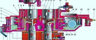
Carburetor design
The unit installed on the “seven”, despite the abundance of parts, is not complicated. Knowing the structure of the carburetor, you can independently replace failed elements.
Main components of the unit:
- a float-type chamber into which fuel is dosed;
- valve to stop the flow of fuel;
- a compartment in which the mixture is mixed;
- dampers, channels, jets;
- spray;
- diffuser;
- pump to speed up the flow.
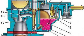
Carburetor diagram:
The principle of operation of the carburetor
The functioning of the power unit is largely determined by the quantity and quality of the incoming fuel mixture.
How the 2107 carburetor works:
Fuel enters the float chamber, the level of which is regulated by a valve or float. After this, the gasoline, divided into droplets, enters the mixing chamber through nozzles, where mixing with the air occurs. The econostat further enriches the mixture when the engine is running at full load. Diffusers optimize the flow of fuel, which is supplied to the manifold through the throttle valves. When the engine runs at high speeds, the accelerator pump turns on.
Main types of jets and their selection
The industry produces 2 types of carburetor jets, which are included in each repair kit:
They are made for each camera of the device. The choice of jet depends on the cross-section of the large and small carburetor diffuser. Repair kits are produced differently - for each model and brand of car. The parts differ in hole diameter. How to adjust the correct operation of the engine - information necessary for every vehicle owner.
Quite often, the Solex carburetor is installed on cars of other brands, with the most powerful engines. In this case, the machine will work intermittently, because the VAZ jets will not be able to do their job efficiently - due to the diameter being insufficient to supply the enriched mixture.
Often, car enthusiasts install a large fuel part for better acceleration and dynamic driving. In this case, one should not forget about the increase in fuel consumption. Also, increasing the diameter of the nozzle by several orders of magnitude will not always give a good result. The table can tell you how to choose jets.
If the engine capacity is 1.6 liters, you should not install a main jet from a powerful engine on it. If you are no longer satisfied with the acceleration of your car, you may need to look for another reason, for example:
- low compression level in one of the cylinders;
- the adjustment of the ignition system has gone wrong;
- one or more spark plugs are faulty;
- Replacement of high-voltage wires is required.
These are just some of the reasons and malfunctions, by eliminating which you will get a fast car again. Car enthusiasts have different opinions about altering jets, but most believe that it is not worth doing. Sometimes, those who like to save money install jets whose sizes are smaller than the recommended ones. In this case, you get an economical, but very weak car that will take a very long time to accelerate. Ozone carburetor jets should not be installed in a Ford carburetor. They should be on the classic Zhiguli.
Correctly tuning the carburetor can have a great impact on the acceleration and power of a vehicle.
VAZ2107 carburetor: how to clean the unit from dirt, step by step
Often, malfunctions of the device are associated with its contamination.
Signs that can help diagnose the problem:
- instability of operation, especially at idle;
- high gasoline consumption;
- jolts and jerks while driving (with the gas pedal pressed).
You can clean the carburetor from blockages on your own. This requires washing the strainer located at the inlet of the float chamber. In addition, cleaning the chamber itself, as well as other components, especially the jets, will help solve the problem.
It is important to remove plaque on the internal walls of the unit, which forms during the operation of the crankcase ventilation system. The walls of the neck, dampers, and diffusers do not need to be cleaned, although if the unit is being serviced, it is better to remove dirt everywhere.
Work technology:
- The top cover is removed (to do this, unscrew the bolts and press out the side spring).
- If necessary, change the filter element.
Important! The condition of the strainer must be checked every 50...80 thousand km. mileage
- The jets are unscrewed.
- The diffusers are dismantled (you can simply pry them off with a screwdriver).
- All channels are purged
- The lower part of the carburetor, secured with two bolts, is removed. To do this, you also need to remove the spring.
- All parts of the carburetor must be cleaned (special attention should be paid to the jets, the holes of which often become clogged), after which it can be assembled.
Important! Gaskets with significant wear are recommended to be replaced.
After cleaning the parts from dirt, the carburetor is assembled.
Installation of used carburetors
It is a widespread practice for UAZ car owners to purchase used units to replace standard carburetors. We will give several recommendations that will allow you to independently prepare them for installation and mount them on the collector.
- Depending on the car model and the carburetor accepted for installation, purchase all the necessary additional components. For example, for UAZ 469 it is necessary to install an adapter on the intake manifold to mount the carburetor on 4 studs. Throttle valve actuators also differ from standard units; you can connect them yourself and using methods, or you can buy them in a retail chain.
- A used carburetor should be disassembled and washed, and all diaphragms and gaskets should be replaced. Before washing, it is necessary to level some surfaces to prevent air leaks through the gaskets. For DAAZ 2107, 2140 and WEBER this is the lower surface of the middle part of the carburetor, for SOLEX - the upper surface of the lower part. The surfaces must be leveled by careful grinding by hand on a grinding wheel. When installing used SOLEX units on a UAZ 31514 or UAZ 469, under no circumstances should the lower surface adjacent to the manifold (sole) be ground in; it is quite thin and cannot be made even thinner. To avoid air leakage from under this plane, before installation, it is necessary to immerse the cardboard gasket, which is placed between the unit and the manifold, in warm water for 1 minute. The gasket will swell slightly and seal the gaps when the nuts are tightened. If the sole is severely deformed, you can use two cardboard spacers. Grinding in the middle part is also necessary when installing K 135 on an UAZ.
- Do not buy or install jet repair kits. This is due to the fact that the retail chain often sells jets whose markings do not correspond to the working hole. From such repair kits, you can use gaskets and diaphragms, and sometimes springs. It would be more correct to use a wooden stick (or a toothpick) to thoroughly clean the working hole of the old jet and install it in its place.
- A separate point is connecting or attaching an air filter to a new carburetor. This can be done on your own and according to your own understanding, observing the tightness condition. Some car enthusiasts replace the standard filter with a dry-type filter element, while others use different adapters to connect the old element. We will offer one universal scheme for DAAZ carburetors: you need to use a filter element together with a pipe from Moskvich 2141. The plastic adapter, fixed on the top platform of the carburetor, will fit in any engine compartment, and the remote barrel-shaped filter has a large capacity for dust, which is an important factor for SUV.
It is recommended to adjust the installed carburetor using a gas analyzer, preferably from a carburetor specialist. It will help not only in setting up, but also in selecting jets for the main metering system in order to give the car the desired properties: traction and dynamics or economy with a calm driving style. Of all the options considered, installing the DAAZ 4178 unit on a UAZ is the most preferable due to the adaptability of the unit to UAZ engines, ease of installation, reliability and cost-effectiveness during operation.
Greetings to all! Problems started with my carb, it began to consume a lot of fuel. I scoured the entire Internet about replacing jets and this is what I found... I think many people will find these tables useful. Good luck to everyone and happy travels!
Cleaning the carburetor without disassembling
In some cases, it is possible to clean the unit without dismantling it. Typically, this need arises when traveling, when it is not possible to get to a service station or remove the VAZ carburetor at home.
To carry out the work, you need to stock up on carburetor cleaning spray.
Important! It is not recommended to use gasoline, diesel fuel or kerosene for these purposes.
How to clean:
- The air filter housing is removed.
- The cleaner treats the XX channels, float chamber, throttle and air dampers, diffusers, jet channels, and drive elements.
- Impurities begin to dissolve.
- After a few minutes, you can spray the cleaner again.
- The engine starts and warms up within five to seven minutes.
- The choke handle is pulled out, the speed increases (you need to press the gas pedal).
- When the power unit is running, the spray is applied to the cavities, flaps and other parts of the carburetor.
- After stopping the engine, spray the aerosol again.
- There is no need to wipe off the cleaner.
- The air filter returns to its place.
It should be noted that subsequently you will still have to disassemble the carburetor on the VAZ 2107, since the dirt accumulated in the float chamber remains there. It will soon clog the jets again.
Replacing the jet
The selection of carburetor jets is carried out according to the markings. The number of each part in the set must correspond to the diameter, according to the table. When choosing a set of carburetor parts, decide what power and take-off speed will suit you. If you are setting nominal dimensions, then everything is simple - you must first select a kit. This is the most important job when purchasing. It should be remembered that 80% of the parts on the market are from China. Pay attention to this when choosing them. Then you can make repairs.
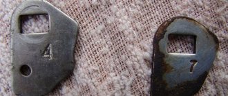
Important. Engines for VAZ cars are produced with DAAZ carburetors. On almost all modifications, the primary chamber is equipped with a 4.5 atomizer. The main fuel jet is marked 135, the air jet is numbered 170. When installing atomizer number 4, 130 fuel and 150 air jets are installed in the first chamber. This ratio must be maintained.
To carry it out we will need to remove the carburetor from the engine. This will make further work more convenient. The carburetor removal diagram is described in other articles on the site; the only thing you need to pay attention to is the gasket between the carburetor and the engine body.