Device
The VAZ 2107 injector consists of the following elements:
- Computer;
- Sensors;
- Fuel pipes and hoses;
- Fuel and air filter;
- Actuators;
- Gas tank;
- Wiring.
The injector power system contains the main element - a computer or ECU. Its permanent memory contains a program (algorithm) in accordance with which the control of actuators is implemented, these include:
- Fuel pump;
- Injectors;
- Idle air control;
- Canister valve.
Each of the above elements performs its own function.
Gasoline pump
Turned on by the ECU output signal through a relay. Has a strainer and fuel level sensor. The gasoline from it passes through the fuel filter. The pump is located in the tank and to remove it, you need to remove the back seat, remove the hatch and unscrew the fastener.
Nozzle
It is a sprayer equipped with a solenoid valve. Triggered by an ECU impulse. Accordingly, the duration of valve opening (the amount of gasoline supplied) depends on the time the pulse is applied. It is installed on a ramp common to all injectors, a constant pressure in which is maintained by a valve. If it is exceeded, the valve opens and gasoline returns back to the tank. The injector enters the intake manifold. The air flow, passing through the intake manifold, carries away a portion of gasoline ejected by the nozzle.
The structure of the VAZ 2107 fuel system
Idle speed control
The fuel system maintains engine idle speed using a regulator. It is a stepper motor connected to a conical shaped control body. Its approach reduces the air flow entering the intake manifold; its removal, on the contrary, increases it.
Canister valve
It is needed to turn on the ventilation of the adsorber, which accumulates gasoline vapors and releases them into the intake manifold at the right moment.
The injector power system contains sensors for measuring, converting and transmitting the signal to the computer.
The following sensors are installed on the VAZ 2107:
- Crankshaft position;
- Mass air flow;
- Throttle position;
- Coolant temperature;
- Speed;
- Oxygen content in exhaust gases.
Crankshaft position
This parameter is needed by the ECU to open the injectors in a timely manner. If this sensor malfunctions, the VAZ 2107 will not drive.
Air flow
Allows you to supply fuel in the right quantity. The signal from this sensor is sometimes incorrect. The reason for this may be its malfunction caused by high humidity or low temperature. An air filter with condensation inside or dirty will adversely affect this sensor.
Throttle position
This signal is analog, i.e. continuous. It transmits precise data about the throttle position.
Coolant temperature
The parameter is needed so that the ECU understands whether the engine is warmed up. This is necessary for the correct operation of a cold motor. The mixture is enriched due to temperature correction.
Speed sensor
Measures and transmits a signal in the form of a sequence of pulses to the ECU.
Oxygen concentration
The oxygen content in the exhaust gases must be measured to adjust the composition of the fuel mixture. It doesn't work when it warms up. This is advisable because the mixture is enriched.
Principle of operation
The internal combustion engine is designed to convert thermal energy into mechanical energy. The conversion process occurs in the cylinder block during combustion of the combustible composition. The preparation and delivery of a mixture of gasoline and air into the combustion chamber of the cylinder is carried out in different ways.
In an engine with external mixture formation, the mixture is prepared in the carburetor. The fuel is mixed with air and enters the combustion chamber through the suction manifold through the inlet valve. It is ignited by a spark plug and burns, expanding the gas, driving the piston.
In an engine with an injection system, the process occurs differently. The fuel-air mixture is prepared in the suction manifold just before entering the combustion chamber.
When the intake valve opens, the injector opens and sprays gasoline. It mixes with air, enters the combustion chamber and at a certain moment is ignited by a candle. From the generated heat, the gas expands and presses on the piston. A working process is taking place.
The VAZ 2107i was equipped with an engine with a distributed injection system, i.e. Each cylinder is supplied with fuel individually through its own injector. There are four injectors according to the number of cylinders.
The injectors, or rather the entire system, are controlled by an electronic control unit (ECU). Judging by its functionality and the amount of work performed, it can be called an on-board computer. All data from electronic and mechanical sensors enters the unit, is processed and commands the actuators to perform certain actions.
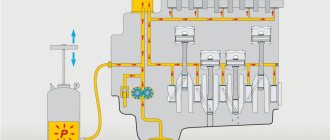
The operating principle is as follows. From the gas tank through the filter, the fuel pump supplies gasoline to the fuel rail, then to the injectors. Inside the ramp, a constant pressure of 300 mPa is maintained using a regulator. If the pressure rises, the excess fuel is dumped into the gas tank through a cutoff automatically.
The ECU sends a signal to open and close the injectors in the order in which the cylinders operate, while being guided by readings from the crankshaft position sensor.
The amount of fuel passing through the injector depends on the length of time it is open. The time is calculated by the control unit using information received from the mass fuel flow sensor and the throttle position sensor.
These are the fundamental parameters under which the engine can operate, but for the correct and smooth operation of the unit, the electronic control unit takes additional readings:
- from a coolant temperature sensor to regulate the combustion process of the fuel-air mixture;
- from a voltmeter to determine the voltage in order to clearly establish the start and end time of the injectors;
- from a tachometer to determine the crankshaft speed;
- from the catalyst to determine the composition of exhaust gases.
The ECU also controls the fuel pump, idle air control and ignition system.
Engine diagnostics
Accurate identification of an engine malfunction and its elimination depends on the reliability of the data obtained. For this you will need good equipment. This includes:
- Engine testers;
- Scanners;
- Gas analyzers.
Reading the error code from the ECU is not everything. It is worth remembering that the data obtained may be unreliable . A sensor malfunction shown by the ECU does not mean that it really is. The problem also occurs due to wiring, poor contact. Therefore, the scanner can only read ECU information. Moreover, the scanner can be implemented as software; in addition, you will need a special adapter, and, of course, a computer.
The other two groups of equipment will allow you to see the full picture, but they are quite expensive. If you want to do diagnostics constantly, then it makes sense to purchase the appropriate equipment and software.
Source
Fuel system valve VAZ 2107 injector
- To the beginning of the forum
- Forum Rules
- Old design
- FAQ
- Search
- Users
The fuel tank in the injection sevens communicates with the atmosphere through an adsorber - a black barrel located in the engine compartment to the left of the engine in the direction of travel of the car. On the line connecting the tank to the adsorber, there is a two-way valve that is blown in both directions. If for some reason this valve jams, then the gas tank begins to either swell from gasoline vapors, or, conversely, become flattened by the vacuum that the pump creates there. Of course, you should check this valve (it is located in the trunk, under the rear window shelf) or eliminate it altogether by connecting the hoses directly. You should also check the safety valve that releases excess gasoline vapor pressure bypassing the adsorber. This is a misaligned plastic valve, located near the filler neck under the plastic casing of the gas tank, connected by transparent blue tubes.
ps We already need to do a fact on these damn valves and pin it.
By the way, the valve is in the trunk under the plastic tank cover. and not under the shelf as mentioned above.
Do you have a Euro-3 car? It's probably done a little differently there.
What else does it manifest? Does it blow from the tank when you unscrew the cap?
YUROK161
No. No need to touch metal valves. One of them is not a valve at all, but a separator, the purpose of which is to separate vapors from liquid gasoline. The second is a gravity valve. While the car is on wheels, it is always open. As soon as she turned over, it closed and prevented gasoline from spilling out.
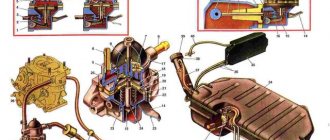
See the diagram that was used on the Euro-2 classic:
9 - gravity valve. 11 - separator. 6 - adsorber. 10 - safety valve.
The two-way valve is not shown in the diagram because it has not been installed before and in general it does more harm than good.
Now I’ll describe how it all works. Gasoline vapors are separated in the separator (11) from liquid gasoline and, bypassing the always closed safety valve (10), pass through the always open gravity valve (9), pass through a two-way valve (if there is one, it is not on this diagram, do not look for it) and enter the adsorber (6), which in turn will then be blown into the throttle (7). Atmospheric air flows back into the tank according to the same scheme, preventing the tank from flattening. If everything works correctly, then no excess pressure or vacuum is created in the tank - everything is smooth, nothing gurgles and there is no smell of gasoline.
Fuel system VAZ 2107 injector (photo and video)
Low fuel pressure, what is the problem Injector!? VAZ The VAZ 2107 injector power supply system has some differences from the classic carburetor. The main distinctive features are caused precisely by the fact that instead of a standard system for supplying the air-fuel mixture to the cylinders, the new VAZ 2107 models use an injector. Accordingly, other elements, such as a pump, filter, etc., differ. In addition to the indicated differences in the fuel system, the VAZ 2107 injection engine has fundamental differences in the ignition system. At the same time, the undeniable advantage of this type of engine is the presence of electronic control of all major systems. It is thanks to it that the efficiency and efficiency of the engine significantly increases.
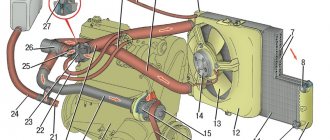
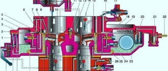
The schematic diagram of the fuel supply system for the VAZ 2107 injector is shown in the following figure.
Here the main elements are indicated by numbers from 1 to 12:
Air intake tube. Filter for air purification. Connecting air pipe. Damper with built-in idle speed control system. Fuel injection system (injector). Filter for mechanical fuel purification. Pump with electronic fuel volume sensor (installed in the tank). Bypass valve. Safety valve. Tank.
In addition, the power circuit contains a system for cleaning and subsequent saturation of air with gasoline vapor, consisting of a fuel purge valve 8 and an adsorber 12.
Adsorber VAZ 2107 (malfunctions, disassembly, removal)
As you can see, the power supply system of the VAZ 2107 injector has a number of significant differences, therefore, the procedure for its maintenance has its own characteristics. As for the air filter, everything is exactly the same as in the case of a carburetor. The filter element is replaced during each routine maintenance.
The pump does not require special maintenance, except for cleaning the fuel strainer installed on the suction pipe. This mesh traps mechanical impurities present in gasoline poured into the tank. If the fuel pump fails, it is replaced. To do this, it is necessary to disassemble the tank, remove the entire pump assembly from it, after which the failed element is replaced. The repaired pump is installed in its regular place in the tank.
mesh filter for rough cleaning from mechanical impurities; fuel supply pump; electronic sensor for monitoring the fuel level (filled in the tank); fuel supply pipe; fuel outlet pipe; electrical connector; float.
The fuel filter is replaced periodically, in accordance with the manufacturer's recommendations. The main element is a special paper insert assembled in a metal case, and it is installed in the supply pipeline between the fuel pump and the injection system. The direction of fuel movement is indicated by an arrow on the body. For example, according to the arrows in the following photo, the pump (fuel tank) should be connected on the right side, and the ramp on the left.
The fuel injection system or fuel rail of the VAZ 2107 engine injector is designed directly to supply the mixture to the engine cylinders.
fuel injectors; feed tube; outlet tube; ramp; spool fitting for pressure control; electronic pressure regulator.
One of the main working elements of the VAZ 2107 engine injection system is the injector. It is essentially an electromechanical valve that is controlled by the engine management system. When voltage is applied, the valve opens and the mixture is injected into the cylinder through the nozzle under the pressure created by the pump. During operation, the nozzles become clogged and therefore require periodic cleaning. As a rule, injectors are cleaned during maintenance, but if engine performance deteriorates, they need to be cleaned without waiting for routine maintenance. Injectors are replaced only when they fail.
Another element of the fuel supply system of the VAZ 2107 engine injector is the throttle valve. It is with its help that the engine speed is controlled, the damper regulates the volume of intake air to prepare the combustible mixture. To prevent freezing of the insides of the damper during the cold season, it is connected to the engine cooling system.
pipe for connecting the adsorber; frame; flap; damper drive; pipe for removing crankcase gases; pipes for connecting to the cooling system; electronic damper position sensor; idle speed control element.
Another new element of the VAZ 2107 engine is the adsorber. It is designed to collect gasoline vapors when the car is idle. After starting the engine, the vapors held by the activated carbon are mixed with air, and the resulting mixture is fed through the throttle valve into the cylinders. In this air exchange scheme, among other things, the tank is involved, which is the main supplier of air saturated with fuel vapor.
In general, the nutrition scheme described above is more effective than the classic one. This is also due to the presence of an electronic engine control system, which regulates injection depending on operating mode, temperature and other factors. And if you follow the manufacturer's recommendations regarding routine maintenance, there will never be any problems with your car.
Do-it-yourself absorber valve replacement
If signs of malfunction are detected, the valve will need to be repaired or replaced. The adsorber valve is inexpensive and easy to replace. To dismantle you need to have a pair of Phillips screwdrivers and know where the canister purge valve is located. Operating procedure:
The markings on the old and new valves must match.
- Open the hood and find a cylindrical device - an adsorber.
- Remove the negative terminal from the battery.
- Disconnect the wire block by pressing the latch and pulling it towards you.
- Loosen the valve.
- Remove the fittings under the latch and disconnect the hoses.
- Remove the valve together with the bracket from the adsorber.
- The new valve is installed in the reverse order.
Thus, even such a small element as the adsorber valve performs important functions and its malfunction can seriously disrupt the operation of the entire engine. Therefore, it is important to monitor the condition of your car and carry out diagnostics on time.
1200 rub. for the photo report
We pay for photo reports on car repairs. Earnings from 10,000 rubles/month.
Many car owners may be interested in the question of how to check the adsorber and its purge valve when the diagnostics showed it to be faulty (an absorber error popped up). It is quite possible to make such a diagnosis in a garage, however, for this it will be necessary to dismantle either the entire adsorber or just its valve. And to carry out such a test, you will need metalworking tools, a multifunctional multimeter (to measure the insulation value and the “continuity” of the wires), a pump, and a 12 V power source (or a similar battery).
Fuel pump repair
To dismantle the electric fuel pump you will need:
- Phillips and flathead screwdrivers;
- 7mm tubular socket wrench.
Removing the electric fuel pump
Dismantling the electric fuel pump is performed in the following sequence:
- The negative terminal of the battery is disconnected.
If you need to replace or wash the coarse filter, you need to pry it off with a screwdriver and remove the old mesh. The new filter is installed by pressing tightly.
The fuel pump is installed in reverse order.
Power supply system for the injection engine of a VAZ 2107 car
The idle speed regulator for VAZ is
– 2107 shut-off valve driven by an electric stepper motor. The regulator is installed on the throttle body under the throttle position sensor. Based on an electronic signal from the control unit (ECU), the idle speed controller changes the cross-section of the additional supply air channel, thereby adjusting the idle speed of the crankshaft. Idle control valve VAZ 2107 Gas tank
car 2107 VAZ - steel, leaded inside, welded from stamped two parts.
The gas tank is located in the trunk of the VAZ 2107 car on the right side. The filler neck of the gas tank is closed with a plug and is brought into the niche of the filler neck on the right wing. VAZ gas tank Fuel
2107 is supplied from the gas tank by a gas pump combined with a fuel level sensor.
A mesh filter is installed on the inlet pipe of the fuel pump, which traps large contaminant particles that enter the gas tank along with gasoline. car on the VAZ 2107 fuel pump is turned on by the Serviceable command. The fuel pump ECU should develop a pressure of not 3 bar, less than 2 bar (320 kPa). electric fuel pump VAZ receiving
1 – 2107 mesh filter; 2 – fuel pump; 3 – fuel level sensor indicator; 4 – supply tube; 5 – drain tube; 6 – electrical connector block; 7 – fuel pump float From the sensor, fuel flows through the fuel pipe into the fuel filter for more thorough cleaning.
Removal
1. Place the car on an inspection hole or overpass (see “Preparing the car for maintenance and repair”).
3. Remove the exhaust pipe from the exhaust manifold studs (see “Reception pipe - removal and installation”).
5. Disconnect the choke drive rod and the throttle drive cross rod from the carburetor (see “Carburetor - removal and installation”).
6. For ease of work, remove the battery (see “Battery - removal and installation”).
7. Using a 13 mm socket wrench, unscrew the nut of the lower air intake mounting.
8. Using the same tool, unscrew the nut of the upper fastening of the air intake and remove it.
9. Unscrew the nut of the upper fastening of the starter heat shield (see “Starter - removal and installation”)
10. Using a 13 mm socket wrench, unscrew the nut securing the eye and remove it.
11. Using the same tool, unscrew the nut securing the “mass” wire and remove it from the stud (for clarity, the chain tensioner has been removed).
12. Using a 10 mm wrench, unscrew the two nuts securing the coolant supply tube to the pump and disconnect the tube. A sealing gasket is installed at the connection point.
13. Using a 13 mm socket wrench with an extension, unscrew the seven nuts securing the intake manifold and exhaust manifold. Under the nuts of the joint fastening of the intake manifold and exhaust manifold, washers of increased thickness are installed.
Intake manifold mounting points
and exhaust manifold
14. Remove the intake pipe from the cylinder head studs and move it to the side.
15. Remove the manifold from the cylinder head studs.
16. Remove the gaskets from the studs.
About installing a fine fuel filter
We should not forget that a carburetor malfunction such as “sneezing” or a sudden loss of power or jerky movement may indicate clogging of the fuel jets. This can happen due to small particles getting into the fuel. The reason could be either low-quality gasoline from the factory or the drain of the last batch of fuel from the tank of a fuel truck that ended up in your tank. If the fuel is not filtered, then repair of the carburetor or fuel pump is not far off.
How effective this “trap” is can be seen in the figure.
If the filter is not installed, you need to install it yourself. On average, the filter resource is 20-30 thousand kilometers. There is no difficulty in the installation procedure, you just need to remember three main points:
There is a rule according to which a fine filter must be installed before the fuel pump. In this case, the fuel pump will last longer and repairs will not be required. For example, in the figure we see an incorrect installation of the filter - after the fuel pump, in addition, the filter is located in a very hot area of the engine. If the housing is cracked, gasoline may leak out, be carried back by the air current onto the hot exhaust manifolds, and cause a fire.
Fuel pump drive
The VAZ 2107 mechanical fuel pump is driven by a pusher and an eccentric. Among drivers, it is customary to call the pusher a rod, although the rod is another part of the fuel pump. The eccentric is located on the intermediate shaft, which operates from the gas distribution mechanism.
The fuel pump drive includes (see figure):
- 1 - pusher;
- 2 — heat-insulating spacer;
- 4 — adjusting gasket;
- 5 - sealing gasket;
- roller (cam).
Device and principle of operation
The operation of the mechanical fuel pump drive is not based on the fact that:
- the oil pump shaft is driven through a timing chain;
- the cam (or eccentric) begins to press cyclically on the pusher;
- The pusher transmits force to the lever and the fuel pump begins to pump fuel.
Drive faults
Problems with the mechanical fuel pump drive lead to interruptions in the operation of the fuel supply system. Actuator malfunctions are most often associated with deformation or excessive wear of the pushrod or cam.
Fuel pump rod bends
The fuel pump pusher is often made of metal that is not strong enough. There are often cases when, after 2–3 thousand kilometers, such a pusher bends and flattens the constant impact of the cam. The length of the pusher should be 82.5 mm. If your fuel pump tappet does not meet this size and is flattened on the cam side, it will need to be replaced.
General diagram of the electrical equipment of the VAZ 21074 injector
General diagram of the electrical equipment of the VAZ 21074 injector
1. Electrical connection diagram of the wiring harness of the instrument panel assembly LADA 21074
- – ignition switch unloading relay;
- – relay-interrupter of direction indicators;
- – windshield wiper relay;
- – brake signal switch;
- – switch for headlights and direction indicators;
- – windshield wiper and washer switch;
- – ignition switch;
- – hazard warning switch;
- – instrument cluster;
- – rear window heating switch;
- – rear fog light switch;
- – external lighting switch;
- – heater motor switch;
- – additional resistor for the heater electric motor;
- – heater electric motor;
- – indicator lamp for heated rear window;
- – brake fluid level warning lamp;
- – instrument lighting switch;
- – cigarette lighter;
- - watch;
- – reverse light switch;
- – hand brake sensor;
- – rear fog light relay;
- – block of the instrument panel harness to the ignition system harness;
- – glove box lighting;
- – mounting block.
Additional designations
The fuses of the VAZ 2107 car are located as follows:
- taillights and reversing lights;
- electric motor of the heater fan, headlight washer and glass wiper pumps;
- indicator for turning on the rear window heater VAZ 2107;
- direction indicators and hazard warning relays;
- fog lights;
- tachometer, voltmeter;
- control lamps for oil pressure, fluid, fuel level and reserve indicators on the instrument panel, instrument panel lighting;
- cigarette lighter and clock;
- VAZ sound signal;
- interior lighting (up to 2000 there was one lamp on the ceiling, for those manufactured after 2000 there were two lamps on the rear door pillars);
- high beam headlights;
- high beam warning lamp;
- engine compartment lighting and license plate lighting;
- glove compartment lighting;
- right headlight;
- left headlight.
PROMOTION: SALE OF NEW CAR 2022 PRODUCTION
We recommend watching:
- Fuel line diagram for VAZ 2110 injector
- Fuel pressure sensor VAZ 2107 injector
- What is the pressure in the fuel rail of the VAZ 2114
- Fuel rail Kalina 8 valves
- How to properly remove the adsorber VAZ 2107 injector
- How to replace the fuel filter on a Lada Priora
How to repair the adsorber and valve
It’s worth noting right away that in most cases both the adsorber and the valve cannot be repaired; accordingly, they need to be replaced with similar new units. However, as for the adsorber, in some cases, over time, the foam in its body rots, which is why the carbon contained in it clogs the pipelines and the solenoid valve of the EVAP system. Rotting of foam rubber occurs for banal reasons - from old age, constant temperature changes, exposure to moisture. You can try to replace the foam separator of the adsorber. However, this cannot be done with all units; some of them are non-separable.
What is the device in question?
The fuel pump on the VAZ 2107 injector is presented in the form of an electric motor with a pump, which pumps gasoline from the tank.
The pump design has an electric motor that is powered from a 12V vehicle network. The design of the electric motor consists of a rotor, brushes and a commutator, which are constantly in gasoline. Many will think that such an injector power system for the VAZ-2107 car is quite dangerous, but not everything is so simple.
Spark and gasoline are a dangerous compound that can lead not only to fire, but also to explosion. This would happen, because sparking occurs in the electric motor of the gasoline pump, if not for the fact that gasoline belongs to the category of liquids that do not conduct electric current. In addition, gasoline does not burn if there is no air, and the fuel circuit is exclusively closed. Thus, the design of an electric fuel pump on a VAZ 2107 car is presented.
Signs of a fuel pump malfunction
A faulty fuel pump can be determined by the following symptoms:
- When starting a cold or warm engine, you have to turn it with the starter for a long time. This may be due to the fact that the required pressure does not build up in the system for a long time;
- the car accelerates poorly, the engine has difficulty picking up speed, the response to pressing the gas pedal is delayed, the car moves jerkily;
- a car with a full tank of gasoline starts, but then can stall at any moment;
- extraneous sounds appeared from the fuel pump - hum, crackling or popping sounds;
- Gasoline consumption has increased sharply, etc.
How to check the adsorber valve
If after checking it turns out that the adsorber is in more or less working condition, then it makes sense to check its purge solenoid valve. It’s worth mentioning right away that for some machines, due to their design, some actions will differ, some of them will be present or absent, but in general the verification logic will always remain the same. So, to check the adsorber valve, you must perform the following steps:
- Visually check the integrity of the rubber hoses included in the fuel vapor recovery system, in particular those directly approaching the valve. They must be intact and ensure the tightness of the system.
- Disconnect the negative terminal from the battery. This is done to prevent false alarms of the system diagnostics and to enter information about the corresponding errors into the electronic control unit.
- Remove the absorber (usually it is located on the right side of the engine, in the area where the air system elements are installed, in particular the air filter).
- Turn off the electrical power to the valve itself. This is done by removing the electrical connector (the so-called “chip”) from it.
- Disconnect the inlet and outlet air hoses from the valve.
- Using a pump or medical bulb, you must try to blow air into the system through the valve (into the holes for the hoses). It is important to ensure the tightness of the air supply. To do this, you can use clamps or a thick rubber tube.
- If everything is in order with the valve, it will be closed and air will not be blown through. Otherwise, its mechanical part will fail. You can try to restore it, but this is not always possible.
- It is necessary to supply electric current from the power supply or battery using wires to the valve contacts. At the moment the circuit closes, you should hear a characteristic click, which signals that the valve has actuated and opened. If this does not happen, then perhaps instead of a mechanical failure there is an electrical failure, in particular, its electromagnetic coil has burned out.
- With the valve connected to an electric current source, you must try to blow air into it in the manner described above. If it is working properly, and therefore open, then this should work without problems. If it is not possible to pump through air, then the valve has failed.
- Next, you need to reset the power from the valve, and there will be a click again, indicating that the valve has closed. If this happens, it means the valve is working.
Source