Hello, dear car enthusiasts! We are considering a rather sensitive topic, to which many may react extremely ambiguously, in some places negatively. After all, we are talking about a flashing brake light.
Considering the capabilities of online stores, as well as the skills of some garage craftsmen, you can buy or assemble almost anything with your own hands.
But before you make your feet with a flashing effect, you should think about the feasibility and legality of such upgrades. Not everyone knows how traffic police officers will react to flashing lights.
Do-it-yourself flashing brake light
Many have noticed that in cars that participate in Formula 1, the brake light not only lights up red, but also flashes. This kind of signal makes it clear that braking is in progress. By analogy, people modify the brake lights of their cars. There are many ways to achieve a flashing brake light, let's look at the most popular ones.
Flashing the brake light using the turn signal relay
You will need the following items:
- turn relay with 3 contacts (792777, 495.3747, 481.3747);
- relay block;
- 3 wires, about 20 centimeters each;
- 3 chips, “dad” type.
Next, we make the connection according to the diagram, namely: plus to pin 49, ground to pin 31, and plus light bulbs to pin 49a.
Result on video
Flashing stop lights based on two timers
This scheme has some advantages, but requires a lot of knowledge, time and effort to implement. It has one difference from the first scheme: the stops blink at the first moment of braking, and then they simply light up as usual.
If desired, you can adjust the flash frequency and blinking duration.
To implement the scheme, the following is necessary:
To bet or not
This is a personal matter for everyone.
And you have your own opinion on this matter. Some are sure that flashing stop signs distract attention and cause a feeling of confusion among drivers moving behind such cars. After all, the intentions of the motorist are not always clear.
It also happens that, due to the flickering, the motorist behind does not have time to brake in time, because he glances at the feet exactly at the moment when the lamp goes out.
There is also the opposite opinion, according to which flickering makes you be more attentive and vigilant. Fans of this theory cite design solutions on Formula 1 cars as an example. After all, their feet also blink during active or sudden braking.
You decide. But remember that such changes can easily be classified as illegal. As a result, the driver faces a fine. And not only the modest 500 rubles. For illegal design changes, sanctions can be much more serious.
Here it would not be amiss to remember why the brake lights do not light up and what this may be connected with.
How to make a flashing brake light with your own hands? Our Guide
Many drivers are interested in how to make a flashing brake light with their own hands. This is perhaps one of the most attention-grabbing types of tuning. This modification is not too difficult to do. Well, the appearance improves significantly. Thanks to this tuning, it’s easy to stand out from the crowd on the road. Of course, not all police officers will be able to appreciate the idea. Therefore, it is advisable to provide a way to quickly disable such a function. The brake lights can operate in a constantly flashing mode. So it’s fragmentary, only immediately after pressing.
It depends on the wishes of the owner himself. You can make only the LED strip flash. It looks quite aesthetically pleasing in combination with statically burning lanterns.
How to make a flashing brake light with your own hands?
To answer this question more fully, you should understand the principle of operation of such a modification. In fact, a special relay is built into a regular circuit. As a result, after pressing the brake, the brake lights begin to operate in pulse mode. After a couple of seconds, normal operation begins. In practice, this looks like a few blinks and then the light just stays on. This attracts the attention of drivers behind. Thus, the risk of an emergency situation is reduced.
This is perhaps the easiest way to make a flashing brake light. True, this scheme is not always reliable. Relay failures are possible, but it all depends on the quality of the build. To make such a device, you can take almost any turn signal relay. But it is best if it is a relay already used on your model. This will make connection work easier and reduce the risk of failure.
The connection is made to standard wiring. This is not difficult to do. It is advisable to add a fuse to the circuit. The same one that is installed in your car on the turn signals will do. Before final installation, it is advisable to check the functionality of the assembled circuit. The disadvantage of this design is the constant blinking of the signal.
Using this chip you can make a brake light control unit. When assembled correctly, you can customize the brake light to your liking. To change the number of blinks, the capacitance of capacitor C1 is changed, as well as the resistance of the resistor. The second chain, C2-R2, regulates the frequency of flashes. In order to avoid problems on the road with law enforcement officers, it is advisable to add to the scheme the ability to quickly disable the function.
This is done in two ways:
- You can install a button with a 1 kOhm resistor in the cabin. When it is pressed, current is supplied bypassing the microcircuit and the stops operate in normal mode;
- A simpler option is to use a regular switch, which is used to switch the brake lights to normal power if necessary.
Tuning
Chevrolet Niva owners also have a way to diversify the appearance of their car. This can be done either by installing new headlights or by upgrading existing ones.
Modernization involves the installation of special trims for the rear light. They can be made from either plastic or acrylic. It is better to use plastic, because despite the higher price they have advantages:
- Not afraid of low temperatures
- protect glass from damage
- are resistant to chemicals. substances - can be painted in body color.
Installing new headlights is a more expensive procedure, but in addition to appearance, it can give the car more functionality. The use of other materials made it possible to create them more vibrant.
https://youtube.com/watch?v=gVRdz1dH6aA
Replacing lamps in the rear lamp, removing the lamp Niva Chevrolet (VAZ-2123)
The work is shown on the left lantern; on the right lantern we perform the work in the same way.
. remove the socket with the lamp from the flashlight body.
Pressing the lamp, turn it counterclockwise all the way.
In addition, on the body of the flashlight next to the lamp socket there is an inscription corresponding to the color of the wire suitable for the socket.
“Mass” wires suitable for all cartridges are black. We carry out the operations for replacing the remaining lamps in the same way. The combined fog and side light lamp has two protrusions located at different height levels.
Location of the light mounting points on the body (shown for clarity with the light removed)
. We insert a suitable stop between the light and the spare wheel on the open tailgate, in this case a sponge for washing the car.
To replace any rear light bulb:
1. Disconnect the wire from the negative terminal of the battery.
2. To gain access to the lamp sockets, bend the flap in the trunk side trim
NOTE
The rear light bulb sockets are practically invisible on the vehicle, so their location is shown for clarity on the removed light.
3. Turn the socket counterclockwise until it stops and remove it from the flashlight body along with the lamp
4. Press the lamp, turn it counterclockwise and remove it from the socket.
5. When installing a new lamp, the protrusions on the lamp should fit into the slots on the socket. Then fix the lamp in the socket by turning it clockwise until it stops (90°).
6. Install the lamp socket into the lamp body by turning it clockwise until it stops.
How to make a flashing brake light with your own hands? Our Guide »
How to make a flashing brake light with your own hands? Our Guide
It depends on the wishes of the owner himself. You can make only the LED strip flash. It looks quite aesthetically pleasing in combination with statically burning lanterns.
How to make a flashing brake light with your own hands?
To answer this question more fully, you should understand the principle of operation of such a modification. In fact, a special relay is built into a regular circuit. As a result, after pressing the brake, the brake lights begin to operate in pulse mode. After a couple of seconds, normal operation begins. In practice, this looks like a few blinks and then the light just stays on. This attracts the attention of drivers behind. Thus, the risk of an emergency situation is reduced.
This is perhaps the easiest way to make a flashing brake light. True, this scheme is not always reliable. Relay failures are possible, but it all depends on the quality of the build. To make such a device, you can take almost any turn signal relay. But it is best if it is a relay already used on your model. This will make connection work easier and reduce the risk of failure.
The connection is made to standard wiring. This is not difficult to do. It is advisable to add a fuse to the circuit. The same one that is installed in your car on the turn signals will do. Before final installation, it is advisable to check the functionality of the assembled circuit. The disadvantage of this design is the constant blinking of the signal.
Using this chip you can make a brake light control unit. When assembled correctly, you can customize the brake light to your liking. To change the number of blinks, the capacitance of capacitor C1 is changed, as well as the resistance of the resistor. The second chain, C2-R2, regulates the frequency of flashes. In order to avoid problems on the road with law enforcement officers, it is advisable to add to the scheme the ability to quickly disable the function.
Ignition system harness
The ignition system ensures the formation of a spark in the cylinders according to the power strokes. In modern engines, wires are connected to sensors that monitor ignition, engine temperature and other parameters.
The ignition system harness 2123 (commonly called “braid”) is indicated in blue in the figure.
In the cabin, it connects to the controller (“brains”), instrument panel, ground and wire from the rear harness. Exiting into the engine compartment, it is divided into two wires.
The largest one is directed to the radiator and along the way it is connected to the mass air flow sensor, crankshaft sensor, resistor, and electric fans.
Throwing over the power steering pump, wires extend from the core to the phase sensors, idle speed, throttle valve, detonation and injectors. This wiring controls the operation of the engine and ensures its smooth functioning.
The second wire runs upward and is divided into two: wires go to the right to the plus and minus of the battery, and to the left to the adsorber, fuel pressure sensor and oxygen sensor.
On models with air conditioning, a branch goes from this harness to its fuse.
If at least one wire in the “braid” is short-circuited, there is a big risk that you will not be able to start the engine. The controller simply will not see information about its temperature, fuel supply to the injectors or throttle position.
In this case, it is better to immediately replace the entire harness than to contact a diagnostician, look for one wire and replace it if the result is questionable.
Do-it-yourself flashing brake light
Once, while in St. Petersburg, I noticed that the car in front had a flashing brake light. It became interesting, I also decided to make myself a similar brake light. Prices for such devices start from 400 rubles.
And I just found several options for a flashing brake light. I chose the famous NE555 timer.
For assembly we need:
Microcircuit - NE555, Diode - 1n4007, Transistor - IRF540, C1- 22uF, C2-10uF, R1-1k, R2- 5k, R3- 10k, R4- 470k, Breadboard, contacts.
Schematic diagram of a flashing brake light
Mounting on mounting plate
The circuit is installed in the brake light panel
I like to solder on a mounting plate. Yes, it’s very tedious, but you don’t have to bother with etching the board.
When soldering, be careful, especially with a field-effect transistor; it is better to hold the legs of the transistor with tweezers for heat dissipation. Strictly observe the polarity or you will burn the entire circuit. To be on the safe side, you can include a diode in the positive bus section of the circuit.
This is how the signal works from the outside.
JavaScript is disabled in your browser
Many people believe that tuning motorcycles is a complex process and to carry it out, you need to contact specialized services. On the one hand, this is true, at least it is better to replace the piston at a service center, but installing the backlight can also be done at home.
What is required to install the backlight?
First of all, you should buy it. To do this, you can go to a nearby auto store and look for diode strips there. In a car store they will be quite expensive and most likely only white. So the best option would be to go to an electrical goods store. Very often you can find the same diode strips there, only half the price, plus a wide variety of colors will be presented. We have completed the purchase of diode strips, we can move on to the next stage. Next, we will need wires; you can get them at the same electrical goods store. You will also need a switch, again we buy it in electrical goods, or take it out of old Soviet TVs. Do not forget that to install the backlight you will need a soldering iron and basic skills in handling it. After you have purchased everything, you can move on to the connection stage.
To connect the diode strip you need to find the plus and minus. At this stage, most people get stuck because they don’t know where to get their power from. Or they start connecting directly to the battery. This, of course, can be done if you have a second battery in stock. In addition, even if you connect everything correctly, it will not be very convenient, because in order to remove the battery you will need to disconnect the backlight power. Therefore, it is better to connect the plus to the fuse; if you burn it, changing it is not so expensive. If you find it difficult to connect to the fuse, you can power the plus from the ignition coil, but this is not advisable. Next you need to find the minus. Again, you can connect it to the battery, but that would be stupid. Therefore, we connect it to the body. To do this, we look for any bolt and check with a tester whether the negative goes through there, that is, we throw one terminal directly onto the negative of the battery, and the other onto the bolt. If you don’t have a tester, don’t be upset, connect the plus of the diode strip to the battery, and the minus to the bolt; if it lights up, you can safely power the minus from this bolt. Next, we move on to the installation itself, to do this we select the place where the diode strip will be attached. For scooters, it’s easy to choose a mounting location, usually it’s the side lining of the bottom, but you can attach it to other places, the main thing here is your imagination. The main thing is that the light from the tape does not blind you or passing drivers, in order to avoid accidents. The correct location for the diode strip will provide visual beauty, but can also add safety in the dark, as you will be better visible. Now let's move on to the switch, we needed it so that the tapes could be turned off. Of course, the ignition can also serve as their switch, but this is not very convenient, since the backlight is almost useless during daylight hours.
How to avoid problems with traffic police inspectors?
Underbody lighting is neither prohibited nor permitted in Russia. That is, everything will directly depend on the mood of the inspector. Therefore, to minimize the risk of issuing a fine, do not use dark blue, as this is the color of special equipment. Also, do not install blinding lighting. If you are stopped by a traffic police inspector, immediately turn off your lights and let them try to prove that they were shining.
Flashing stop light
In previous publications, the topic of a brake light with dynamic lighting has already been touched upon, or rather, a version of a brake light with running lights was mentioned. See the article "Brake Signal Running Lights". Some will be content with the normal flashing of brake lights. In traffic, this will attract the glances of other road users. And there is even an advantage of this option - the complexity of the circuit will be quite low. It is the flashing signal that will be discussed in this article.
So, a simplified flashing brake light is obviously inferior in terms of entertainment value to its older brother, but this option is also much easier to make. Every cloud has a silver lining. Meanwhile, there is some point of adjustment in this case, namely adjusting the blinking frequency of the LEDs. This can be controlled using capacitors of various capacities. From words to deeds - let's turn to the electrical diagram
Possible punishment
There is nothing in the traffic rules, but there is something in the technical regulations. Hence the logical question about whether they can be punished for flashing lights, and what the possible fine is in such a situation.
Here, traffic police officers will build on Article 12.5 of the current Administrative Code. The emphasis is on the fact that a flashing stop indicates an incorrect operating mode of the equipment. As a result, a fine of 500 rubles. But in addition, the driver may also suffer for making changes to the design of his vehicle.
Electrical circuit of a blinking brake light “option 1”.
A do-it-yourself flashing brake light can be made based on the brake light circuit with running lights already known to us, which was described in previous issues. The circuit is based on the KA561LA7 microcircuit; 2 of its elements contain a multivibrator. To obtain a higher-quality digital signal at the output, the third element of the microcircuit is used as an inverter, playing the role of a separator of the analog circuit and a multivibrator. As we mentioned above, the blinking frequency directly depends on the capacitor capacity. The relationship is inverse - the higher the capacitance of the capacitor, the slower the blinking occurs. On the other hand, a capacitor with a smaller capacitance will provide a higher blinking frequency. Along with this, the resistor located in the capacitor circuit also has some influence on the frequency - a recharging cycle of the capacitor occurs through it.
Now let's talk about how the power part of the circuit works. The control signal is supplied to the base of the KT816B transistor. During the positive half-cycle, the transistor turns into a conductor, passing electric current through itself. Thanks to this, we get much more power at the output of the transistor than we could get using only microcircuits.
This means that there will be enough power to connect the LED chain. The KR142EN 5 B microcircuit is recommended as a fuse or voltage stabilizer. As is known, in this case the voltage will be stabilized at a level of 5 V. Read more in the article “How to get 5 volts from 12 volts”
Relay and fuse diagram for Chevrolet Niva after 2009 (restyling)
Year of release
| 2009 | 2010 | 2011 | 2012 | 2013 | 2014 | 2015 | 2016 | 2017 | 2018 | 2019 and present |
Relay circuit
| Number on the diagram | What is he responsible for? |
| K1 | not used |
| K2 | windshield wiper relay |
| K3 | relay-interrupter for direction indicators and hazard warning lights |
| K4 | low beam headlight relay |
| K5 | headlight high beam relay |
| K6 | additional relay |
| K7 | Rear window defroster relay |
| K8 | reserve |
Fuses and inserts
| Number | What is he responsible for? | Current strength, A |
| F1 | License plate lights, side light lamps in the left headlight and left rear light, engine compartment lamp, side light indicator lamp | 5 |
| F2 | Low beam lamp left headlight) | 7,5 |
| F3 | High beam lamp, left headlight unit), indicator lamp for turning on the high beam headlights | 10 |
| F4 | Left fog lamp | 10 |
| F5 | Power window relay, front power windows | 30 |
| F6 | Cigarette lighter fuse | 15 |
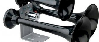
| F7 | Horn Relay, Horn, Trunk Lamp | 20 |
| F8 | Heated tailgate glass element, heated tailgate glass relay, heated outside rear view mirror elements | 25 |
| F9 | Heated tailgate switch, windshield wiper relay, windshield wiper motor, windshield washer pump, right steering column switch, glove compartment lamp, reverse lamps | 20 |
| F10 | Remote control unit for electrical accessories (door lock) | 20 |
| F11 | Side light lamps in the right headlight and right rear lamp, instrument lighting brightness control | 5 |
| F12 | Low beam lamp, right headlight), gear motors for headlight beam control | 7,5 |
| F13 | High beam lamp, right headlight) | 10 |
| F14 | Right fog lamp | 10 |
| F15 | Outside mirror control unit, electric outside rear view mirrors, heated seat control unit | 20 |
| F16 | Relay-breaker for direction indicators and hazard warning lights | 10 |
| F17 | Interior lamps, anti-theft system status warning lamp, brake lights, additional brake light | 7,5 |
| F18 | Heater fan, heater fuse | 25 |
| F19 | Relay-interrupter for direction indicators and hazard warning lights (in turn signal mode), instrument cluster (except for engine management system malfunction warning lamp), starter relay | 10 |
| F20 | Fog lamps in the rear lights, anti-theft control unit, buzzer | 7,5 |
Remote relays
| Number | What is he responsible for? |
| 1 | Fog lamp relay (FTL) |
| 2 | Power window relay |
| 3 | Seat heating relay |
| 4 | Horn relay |
| 5 | Starter relay |
Located under the glove box on the passenger side.
| Number | What is he responsible for? |
| 1 | Additional relay (turns on the right electric fan through an additional resistor at low rotation speed) |
| 2 | Fuse (50A) protecting the power circuits of the additional relay and the right electric fan relay |
| 3 | Fuse for the fuel pump (fuel pump) (15A), protecting the power circuits of the electric fuel pump relay |
| 4 | Fuse (15A) protecting the controller's constant power supply circuit |
| 5 | Right electric fan relay |
| 6 | Left electric fan relay |
| 7 | Fuel pump relay |
| 8 | Main relay |
| 9 | Fuse (50A) protecting the left electric fan circuits |
| 10 | Fuse (15A) protecting power circuits switched on by the main relay |
| 11 | Controller |
Circuit elements - DIY replacement options for a flashing brake light
Microcircuit - let's first consider its analogues. The easiest way is to get the American version CD4011A “Texas instruments”. It will be quite difficult to find a chip made in the USA, but there are plenty of Chinese options on the market.
Capacitor C1 has the following parameters: current is alternating, voltage above 16 V. Resistors must cope with a power of at least 0.25 W. You can install any LEDs that meet the voltage requirement above 3.3 V. Color is also an important indicator - brake lights should be red.
A universal circuit board will do an excellent job as the basis of our circuit; you just need to organize the connection of the elements with flexible conductors, which in itself is the simplest way to implement it. Also, no configuration or adjustment is required; it is only important to assemble everything correctly and preferably test it before putting it into operation.
The only drawback is the absence of any control based on the blinking principle. This circuit ensures that the brake light blinks from the moment you press the brake until it is completely released. It is logical to assume that it would be worth blinking for 3-4 seconds after pressing, and then shining constantly. In the following diagram we will look at the implementation of just such an option.
Testing homemade LED headlights
After about 2 hours of testing, the system reached a temperature of about 35 degrees, that is, despite the use of resistors instead of chip inverters, much less than an equivalent incandescent lamp.
The uniformity of backlight shades is not ideal. The lower part of the headlights is good - the diodes shine perfectly with rows of lenses and illuminate evenly. Higher up - due to the tilt of the glass LEDs, the light begins to scatter a little, and the brightness depends slightly on the viewing angle.
It would have been possible to customize the LED strips in stages, but the priority was to provide a reasonable cost-to-effort ratio that would completely satisfy the car owner.
The time investment for these car tail lights is 3 days to 2-3 hours a day, and the cost of materials for both lamps is 3000 rubles - this is very good.
Electrical circuit of a blinking brake light “option 2”.
This scheme implements the option of blinking during the first moments of the brake lights, and then the LEDs should shine evenly, without flickering. The circuit is based on 2 timers based on NE 555 microcircuits. First, the generated control signal is discretely supplied to the transistor in the same way as the first circuit, and then a constant voltage is generated on its basis. Eventually the relay stops working and becomes a conductor.
Note that if it is necessary to eliminate the influence of the circuit, it is necessary to move the switch SW1 to position 1-2. However, the transistor and relay will be used after such a switch.
To enlarge the diagram of a flashing brake light, just click on the picture; there is also a description and marking of the parts.
The circuit board for a blinking brake light with your own hands may look like the image below, and the circuit can also be implemented on a universal circuit board.
Shown here is a version of the finished board from the track side.
On the top side is the side where the parts are soldered.
Removal and replacement
The rear lights of the Niva Chevrolet, as on other cars, are rarely changed, only if the glass is damaged. To change faulty lamps it is not necessary to completely remove them.
To complete this procedure, you must follow a certain procedure:
- We remove the terminals from the battery so as not to cause a short circuit during operation.
- Then we open the trunk and remove the part of the trim that covers the mount.
- The part is secured with 4 bolts, which can be unscrewed with a 10 mm ratchet wrench.
- Disconnect the wire terminals.
After this, you can install the new one in reverse order.
In order to replace a faulty lamp, it is not necessary to completely remove the lamp. It is enough just to lift the part of the casing that covers the cartridges. Then we press the plastic clips to remove it and replace the burnt out lamp with a new one.
Results of the work carried out
There are several options for creating such an intermittent stop signal. Both how the scheme will work and what the result will be are different. At the same time, any of the options can be easily implemented independently; both the simplicity of the electrical circuits and the low cost of the components will help.
The absence of the need to use programmable controllers can also be recorded as an asset.
Now it’s up to you to choose the most suitable option and organize revisions. We wish you that the information received will be useful to you, and the result will meet your expectations!
When to replace
Brake lights, as a rule, burn out at the most inopportune moment, or it happens that they stop working correctly, this especially often happens if it performs two functions, dimensions and stops, and it turns out that the dimensions work, but the stops do not. In addition, if the contact is poor, the light may begin to blink. In these cases, it is necessary to replace the rear brake light bulb. It is also quite rare to change the working lamp, this is done if the result from the standard one does not suit you, and you want to get a better result, in this case it is changed to LED lights, since it has a number of advantages such as:
- Specific luminous efficiency is better
- The operating time is 100 hours, which is significantly higher than that of a simple lamp, for which these hours are equal to two thousand
- It flares up instantly, thereby warning vehicles behind you about your braking earlier.
- High performance properties, which allows you to extend work, despite the vibrations that occur when driving on our roads
LED Strip Light
Before the installation process itself, let's look at the material, that is, the tape itself. In the store, the price for this pleasure starts from 100 rubles (30 UAH) per meter. The price may increase depending on the number of LEDs (from 30 per meter), brightness and color. Such tapes have a relatively long shelf life, and they will also consume a small amount of electricity. You can easily install the tape anywhere on the scooter, it is so flexible that the backlight can be placed in any desired place. And if you don’t know which color to choose, use the most popular and quite beautiful colors - blue or green.
Step-by-step instruction
Installing LEDs on a strip
Installation of LEDs on the rear lights is carried out in the following sequence:
- The flashlight must be removed from the car. Next, it needs to be cut into two parts - a high-quality burning device can handle this. The result should be an even and thin seam.
- Now you have access to the reflectors and reflectors - they need to be removed.
- The taillights need to be completely disassembled. It is recommended to mark with a marker the position of future LEDs on external surfaces.
- Inside you need to stick circles of self-adhesive film with a diameter of 15 mm.
- The surface of the side lights and brake lights must be coated with silver paint. When the paint is completely dry, the self-adhesive film can be removed.
- The reflectors are installed on a small layer of epoxy glue. After this, you can coat all joints with sealant as a preventative measure.
- The LED boards are attached to the wiring and placed in the headlight housing.
- A stabilization circuit is installed that will regulate the LED connections.
- The pivot blocks can now be assembled and connected to the taillight. It is necessary to place the modules on epoxy glue. If the optics are working properly, then you can glue the block together - the tuning is complete.
Reasons for lack of spark
Often, owners may encounter cases of starting failure in the cold season, although the moped drove well in the autumn. Initially, you need to unscrew the spark plug and carefully inspect for spark, oiliness and color.
Carbon deposits on the electrode
There may be no spark, if the electrode is covered with carbon deposits, then they are cleaned with a metal brush. If there is even the slightest doubt about the serviceability of the spark plug, you should replace it immediately, thereby making your life easier in the future.
Acidification of contacts
If the external signs of the spark plug correspond to suitability, and there is also no spark, then you need to check whether there is a discharge. It is worth noting that you need to be extremely careful, as it can give you an electric shock. If there is no spark and the external signs of the spark plug are normal, then the scooter is checked electronically for acidification of the contacts.
Insufficient fuel
If there is a spark, but the moped still has difficulty starting from the starter in cold weather, you should pay attention to the fuel tank. If it is empty then it is filled
It is worth noting why old gasoline pours out of the carburetor float chamber. How to do it? There is a bolt at the bottom of the carburetor; it is unscrewed, and after all the fuel has flowed out, it is screwed back in. Before putting the moped in the garage in cold weather, fill the tank full of fuel.
Unscrew the bolt and pour out the old gasoline from the carburetor float chamber
If the above has been checked and done, and the scooter does not start well from the starter, then you can make the following repairs:
- The carburetor is removed and the air filter is cleaned;
- The carburetor is cleaned, the jets and channels are purged;
- Everything is coming back together.