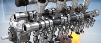
For a long time, a carburetor engine power supply system was used to produce and deliver the combustible mixture to the cylinders of internal combustion engines and to remove exhaust gases. It performs the following tasks:
- mixes air and fuel in the required ratio;
- prepares a homogeneous mixture;
- transports it to the cylinders;
- removes exhaust gases from the internal combustion engine.
The production of a fuel-air mixture is called carburetion. The general structure of a carburetor engine consists of the following functional units:
- Devices in which gasoline is stored and its volume is measured.
- Fuel filters.
- Devices for fuel delivery.
- Air filters.
- Devices for producing a fuel-air mixture.
- Devices that supply it to the cylinders.
- Devices for removing exhaust gases and reducing noise when they come out.
How does a simple carburetor work?
The following stages can be distinguished in the functioning of the carburetor power system:
- Fuel is pumped out of the tank and flows through the pipeline, ending up in the carburetor. In this case, the fuel level in the gas tank is controlled by an indicator, in the electrical circuit of which there is a sensor.
- Gasoline is purified using a sediment filter and a fine filter.
- Air enters the carburetor after the air filter.
- The prepared fuel-air mixture from the carburetor enters the cylinders through the intake manifold. It heats up in it.
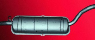
- Exhaust gases are removed from the engine by the exhaust system. It includes a pipeline, a pipe and a muffler that reduces the noise level when releasing gases.
Pump
It ensures the supply of gasoline for injection and maintains the required level of pressure for the correct operation of the fuel line as a whole. The fuel pump of a carburetor engine is mounted directly into the gas tank structure and is equipped with an electric drive. In some car models, you can install a booster pump as an additional reinforcing element.
Fuel jet formation
From the gas tank, fuel enters the float chamber. The fuel in it is always at a constant level. A float and a fuel valve are used for this. When the tank is filled with fuel to the maximum level, the needle is pressed against the seat by the float. Thus, the flow of gasoline stops.
When the fuel level decreases, the float begins to descend. As a result, gasoline enters the chamber. An increase in gasoline consumption causes a decrease in its level. This leads to an increase in the flow area for fuel. A gap for gasoline is formed between the needle and the seat. A pipe is attached to the float chamber.
Even at maximum filling, the gasoline in it is lower than the edges of the nozzle outlet. Thanks to this, fuel does not leak out when the internal combustion engine is not running.
Air enters the carburetor through the main air channel. In the middle its cross-section decreases. Due to this, a diffuser is created. It accelerates air flow, improves gasoline evaporation and mixture formation, and increases draft in the atomizer. The narrowest part of the diffuser is connected to the end of the atomizer. The throttle valve regulates the amount of fuel-air mixture that enters the cylinders.
The damper is connected to the pedal. When you click on it, it changes its position. The more the valve opens, the more volume of the fuel-air mixture enters the cylinders. As a result, the power produced by the motor increases. This regulates the volume of the combustible mixture that enters the cylinders.
Fuel jet breakdown
From the nozzle, fuel rises into the atomizer, which consumes energy. When the difference between the speeds of gasoline and air reaches 4-6 m/s, the fuel stream disintegrates. Droplets in size reach 20-120 microns, the optimal value is considered to be 50 microns.
The higher the temperature of the fuel, the smaller the droplets. This is explained by a lower surface tension coefficient and an increase in the difference between the speeds of gasoline and air.
Fuel injection systems
Fuel injection systems are currently used much more often than carburetor systems, especially on gasoline engines of passenger cars. Gasoline is injected into the intake manifold of an injection engine using special electromagnetic injectors (injectors) installed in the cylinder head and controlled by a signal from the electronic unit. This eliminates the need for a carburetor, since the combustible mixture is formed directly in the intake manifold.
There are single-point and multi-point injection systems. In the first case, only one injector is used to supply fuel (with its help, the working mixture is prepared for all engine cylinders). In the second case, the number of injectors corresponds to the number of engine cylinders. The injectors are installed in close proximity to the intake valves. The fuel is injected in a fine spray onto the outer surfaces of the valve heads. Atmospheric air, entrained into the cylinders due to rarefaction in them during intake, washes fuel particles from the valve heads and promotes their evaporation. Thus, the air-fuel mixture is prepared directly at each cylinder.
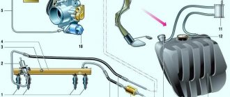
In an engine with multipoint injection, when power is supplied to the electric fuel pump 7 through the ignition switch 6, gasoline from the fuel tank 8 through filter 5 is supplied to fuel rail 1 (injector rail), common to all electromagnetic injectors. The pressure in this ramp is regulated using regulator 3, which, depending on the vacuum in the inlet pipe 4 of the engine, directs part of the fuel from the ramp back to the tank. It is clear that all injectors are under the same pressure, equal to the fuel pressure in the rail.
When it is necessary to supply (inject) fuel, an electric current is supplied to the winding of the electromagnet of injector 2 from the electronic unit of the injection system for a strictly defined period of time. The electromagnet core, connected to the injector needle, is retracted, opening the way for fuel into the intake manifold. The duration of the electrical current supply, i.e. the duration of fuel injection, is regulated by the electronic unit. The electronic unit program at each engine operating mode ensures optimal fuel supply to the cylinders.
Rice. Diagram of the fuel supply system for a gasoline engine with multipoint injection: 1 - fuel rail; 2 — nozzles; 3 - pressure regulator; 4 — engine inlet pipe; 5 - filter; 6 — ignition switch; 7 - fuel pump; 8 - fuel tank
In order to identify the engine operating mode and calculate the injection duration in accordance with it, signals from various sensors are sent to the electronic unit. They measure and convert the following engine operating parameters into electrical impulses:
- throttle angle
- degree of vacuum in the intake manifold
- crankshaft speed
- intake air and coolant temperature
- oxygen concentration in exhaust gases
- Atmosphere pressure
- battery voltage
- and etc.
Engines with gasoline injection into the intake manifold have a number of undeniable advantages over carburetor engines:
- fuel is distributed more evenly among the cylinders, which increases engine efficiency and reduces engine vibration; due to the absence of a carburetor, the resistance of the intake system is reduced and cylinder filling is improved
- it becomes possible to slightly increase the degree of compression of the working mixture, since its composition in the cylinders is more homogeneous
- optimal correction of the mixture composition is achieved when switching from one mode to another
- provides better engine response
- exhaust gases contain less harmful substances
However, power systems with gasoline injection into the intake manifold have a number of disadvantages. They are complex and therefore relatively expensive. Servicing such systems requires special diagnostic instruments and devices.
The most promising fuel supply system for gasoline engines is currently considered to be a rather complex system with direct injection of gasoline into the combustion chamber, which allows the engine to operate for a long time on a very lean mixture, which increases its efficiency and environmental performance. At the same time, due to the existence of a number of problems, direct injection systems have not yet become widespread.
How does gasoline move?
Air flows 25 times faster than gasoline. A carburetor works on the same principle as a spray gun. There is a pressure difference between the float chamber and the diffuser. This causes gasoline to leave the float chamber, moving through the calibrated fuel hole and the nozzle to the diffuser.
Then the fuel ends up in the main air channel. Today, the pressure at which gasoline transportation begins is 100 Pa. If the value is less, then only air flow moves through the carburetor.
The speed of the air flow passing through the diffuser increases. For this reason, the pressure in the spray area decreases. When the motor is not running, there is no pressure difference between the float chamber and the spray area.
When starting the engine, suction creates a draft in the cylinder. Because The spray area communicates with the cylinder using the inlet pipeline and the main air calibrated hole, then the draft from the cylinder reaches the spray zone.
After this, a pressure difference appears between the chamber with the float and the diffuser, which leads to the movement of gasoline from the chamber to the atomizer. Then, in the main air channel, the fuel forms a mixture with air and moves to the cylinders.
Movement of air and fuel-air mixture
The acceleration of air when moving through the diffuser is facilitated by the formation of draft in the spray area. Reducing the diffuser size is possible only up to a certain value. Otherwise, there will come a time when reducing the diffuser will lead to an increase in resistance to air flow.
As a result, engine power will decrease because the cylinders will become less filled. The part of the tube that connects the diffuser neck to the throttle shaft is called the “mixing chamber”.
Not all gasoline is involved in the formation of the fuel-air mixture. This occurs because some of the gasoline does not evaporate and is not mixed with the air flow. Unused fuel droplets move with the air. Encountering the walls of the mixing chamber and exhaust pipe along the way, fuel residues are deposited on them.
This creates a film that moves slowly. To evaporate it, the intake pipe is heated during operation of the internal combustion engine. There are 2 types of heating:
- using liquid, for this they use the engine cooling system;
- due to the heat of the exhaust gases.
Types of carburetors
The fuel-air mixture is finally formed in the intake pipe of the internal combustion engine. The air flow in the mixing device can move in different directions. Therefore, carburetors come in several types:
- Devices in which the flow of the mixture decreases, i.e. flows from top to bottom. They are distinguished by high power, efficiency, and convenient location on the engine for repairs.
- Devices in which the flow of the mixture is upward, i.e. it moves from bottom to top. These are outdated designs.
How to improve the formation of the fuel-air mixture
The difficulty of producing a fuel-air mixture lies in the fact that this process is carried out very quickly. Air and mixture pass through the engine intake tract at a speed of 30 - 100 m/s, and the mixture formation time does not exceed 20 ms. Factors that improve mixture formation and evaporation of gasoline:
- easily evaporating liquid as a fuel;
- expansion of the area of vaporization due to atomization of gasoline and blowing of fuel droplets;
- a decrease in pressure in the environment into which the fuel enters;
- heating gasoline and air;
- introduction of emulsion liquid using a sprayer.
Improved carburetor engines
Increasing the throttle opening causes more air to flow through the carburetor. As a result, it accelerates and creates additional thrust in the diffuser. This causes increased gasoline consumption. In this case, the necessary correspondence between the increase in the amount of air and fuel is not satisfied.
Due to this, the fuel-air mixture produced with a large throttle opening is enriched. Since the operating modes of the internal combustion engine are different, the mixture produced by a simple carburetor does not correspond to the required composition. During low loads, the draft in the diffuser is so low that it is generally impossible to prepare a fuel-air mixture.
To eliminate this drawback, the carburetor power supply system is equipped with additional devices. When using them, the fuel-air mixture prepared during different modes is very close to the required one.
Cars with carburetors operate in the following modes:
- Start the engine. At this point, the fuel does not evaporate well, so a rich mixture must be used.
- Idling and light loads.
- Partial loads.
- Full loads.
- Sudden opening of the damper. In this mode there should not be a mixture with a high air content.
Different operating modes of the internal combustion engine are accompanied by the activation of the corresponding systems and devices:
- starting device;
- idle system;
- main dosing device;
- economizer;
- accelerating pump.
Let's describe each in detail:
- The starter reduces the amount of air that moves through the carburetor. At the same time, the draft in the diffuser increases. As a result, the nozzle of the main dosing system is empty, because The gasoline contained in it flows out and a fuel-air mixture is created. After the first flash occurs, air moves through an automatic valve on the trigger device. When the engine heats up, the starter must be opened slightly manually. To automate the process, some internal combustion engines use automation.
- The idle system produces mixture while the main metering system is inactive. It consists of a nozzle with two holes, an adjusting screw, two channels, air and fuel calibrated holes.
- The main metering device is distinguished from a simple carburetor by the presence of a well and a calibrated air hole. The latter connects the well to the atmosphere.
- The economizer starts working at full load. Depending on the drive, it can be of two types: mechanical or pneumatic. The first consists of a valve, a calibrated hole, a pusher and its movable stand. The length of the pusher is adjustable. At a certain length, the economizer is turned on. The pneumatic device starts at a certain crankshaft speed.
- The accelerating pump operates under special vehicle driving conditions. For example, when overtaking, climbing
The use of the described devices makes it possible to make the operation of a carburetor internal combustion engine more efficient, increasing its power and reducing fuel consumption.
Malfunctions and service
During the operation of the vehicle, the vehicle's fuel system experiences loads that lead to its unstable operation or failure. The following faults are considered the most common.
Insufficient supply (or lack of supply) of fuel to the engine cylinders
Poor quality fuel, long service life, and environmental exposure lead to contamination and clogging of fuel lines, tank, filters (air and fuel) and technological openings of the combustible mixture preparation device, as well as breakdown of the fuel pump. The system will require repairs, which will consist of timely replacement of filter elements, periodic (every two to three years) cleaning of the fuel tank, carburetor or injector nozzles and replacement or repair of the pump.
Engine power loss
A malfunction of the fuel system in this case is determined by a violation of the regulation of the quality and quantity of the combustible mixture entering the cylinders. Troubleshooting involves the need to diagnose the combustible mixture preparation device.
Fuel leak
A fuel leak is a very dangerous phenomenon and is absolutely unacceptable. This malfunction is included in the “List of malfunctions...” with which the vehicle is prohibited from moving. The causes of the problems lie in the loss of tightness of the components and assemblies of the fuel system. Troubleshooting involves either replacing damaged system elements or tightening the fuel line fastenings.
Thus, the power system is an important element of the internal combustion engine of a modern car and is responsible for the timely and uninterrupted supply of fuel to the power unit.
What else is worth reading
VAZ 2109 generator device
The design of the chassis of the VAZ 2109
Intake manifold device
Fuel pump
Carburetor malfunctions
We will describe the main malfunctions of the carburetor engine power system and how to eliminate them:
- Malfunctions in the fuel filter. If there are malfunctions in the power supply system of a carburetor engine, first check the fuel filter. To inspect it, you will need to unscrew the cap and remove the filter. Next, you will need to rinse with gasoline. If damage is detected to the filter and supply pipe, they must be replaced.
- There is little or no gasoline in the float chamber. At the same time, there are no problems with the strainer. This malfunction could have occurred due to the accumulation of dirt in the fuel needle valve connected to the float chamber cover. The mud created obstacles to the flow of fuel. For normal functioning of the carburetor, it is necessary that the valve moves freely in the seat and that the ball does not hang up. To remove dirt from the valve, it is enough to rinse and blow it.
- The float has gone astray. This problem is indicated by unstable engine operation, jerking, a sharp increase in gasoline consumption, and deviations from the norm in the fuel level in the chamber with the float. To adjust the operation of the needle in the valve, it is necessary that the fuel is at the desired level. In addition to this, you need to make a small bend in a specially designed tongue and travel stop for the float. If the hole in the latter is small and there is no time to fix the problem now, then the float can work sealed for a short period.
- Difficulty starting the engine, although there is enough fuel in the chamber. It is necessary to check the calibrated holes and channels of the carburetor for contamination. The carburetor will need to be partially disassembled. This comes down to removing the cover from the camera. Cleaning the channels and calibrated holes with gasoline and blowing them with a pump using compressed air helps remove dirt.
- It is difficult to start the internal combustion engine after a long period of parking. The cause may be wear on the diaphragm, which is connected to the carburetor trigger. If at the moment it is not possible to eliminate the problem, then for a short period you can take the following actions. Take a small piece of aluminum wire and bend one end into a loop. Next, attach the wire to where the carburetor is connected to the air cleaner. In this case, it should be fixed so that the nut is above it. Then the second bent end of the wire is installed in the place where the upper part of the air regulator is pressed in the first cylinder. This creates a gap of 3 - 4 mm, separating the air regulator and the wall of the first cylinder. The presence of the formed gap will help to start the engine. But this method is suitable only for a short time, after which it will be necessary to eliminate the cause of the problem.
- Engine malfunctions. For example, it stops functioning after the driver releases the gas pedal. This malfunction may occur due to contamination in the idle system of the calibrated hole through which the emulsion passes. To fix the problem, you will need to remove the calibrated hole. To do this, you will need to free the air filter from the housing. If the calibrated hole is very dirty, it must be cleaned using a sharpened wooden stick moistened with acetone.
- The tightness of the connection between the intake pipe and the carburetor is broken. The problem area can be detected by traces of soot and the presence of a thin film of fuel.
- A rupture in the connections between the exhaust pipe and the flange and the damper body and the inlet pipe. As a result, air enters the system, increasing the amount of gasoline consumed. In this case, the operation of the muffler may be accompanied by strong pops. Soap scum can be used to detect leaks. It will have a hole in areas where it breaks.
- The engine speed fluctuates at idle, and the internal combustion engine stalls. Jumping speed is indicated by a jumping tachometer needle. There may be several reasons. Failure to regulate the composition of the combustible mixture, problems with the solenoid valve or control circuit, dirty channels and calibrated holes in the idle system, faulty economizer on forced idle (crack in the membrane). Replacing the faulty mechanism and restoring the electrical wiring will help eliminate these problems.
For a comfortable and safe ride, it is necessary to carry out regular maintenance and use high-quality gasoline. If problems are detected in the operation of the carburetor, it is necessary to identify the cause as quickly as possible and eliminate the problem.
The carburetor prepares the combustible mixture, which enters the cylinders through the intake manifold. The exhaust pipe removes exhaust gases from the cylinders. The muffler reduces the noise of exhaust gases escaping into the atmosphere.
The principle of operation and general structure of the carburetor. The body of a simple carburetor contains a float and mixing chambers. The float acting on the needle valve maintains a constant fuel level in the float chamber. The hole communicates the float chamber with the atmosphere.
In the upper part of the mixing chamber there is an inlet air pipe, in the middle there is a diffuser with a narrowed flow area (neck), and in the lower part (outlet pipe) there is a damper called a throttle, mounted on a roller passed through holes in the walls of the mixing chamber. Using the lever at the outer end of the throttle shaft, the latter can be rotated to the required position. The outlet pipe of the mixing chamber is connected to the engine inlet pipe via a flange.
The cavity of the float chamber is connected to the atomizer, led into the neck of the diffuser, by a jet having a calibrated hole. The upper section of the nozzle is located above the fuel level in the float chamber; fuel does not flow out by gravity.
During engine operation, atmospheric air entering the cylinders during intake strokes passes through the mixing chamber, in which, as in the cylinders, a vacuum is formed equal to the pressure difference between the atmospheric and the mixing chamber. It is known that when a liquid or gas moves through a pipeline, its pressure in the narrowed section decreases and its speed increases. Therefore, the greatest vacuum, and therefore the maximum air speed, is created in the neck of the diffuser.
Rice. 21. Diagram of the design and operation of a simple carburetor: 1 - mixing chamber; 2 — diffuser; 3 — inlet air pipe; 4 - sprayer; 5 — air hole of the float chamber; 6 — float chamber; 7 - needle valve; 8 — float; 9 — jet; 10 - throttle; 11 — engine inlet pipeline; 12 — throttle lever.
Due to the difference in pressure - atmospheric in the float chamber and lower in the diffuser - fuel flows out of the nozzle hole and is atomized by a stream of air moving through the diffuser.
The process of preparing the combustible mixture, which began in the carburetor, continues in the intake manifold, as well as in the engine cylinders during the intake and compression strokes.
The composition of the combustible mixture prepared by the carburetor depends on the size of the nozzle passage: the larger it is, the more fuel the nozzle passes to the nozzle and the richer the mixture is formed. The amount of mixture entering the cylinders is controlled by the throttle.
A significant drawback of the described carburetor is that it does not provide the required mixture composition under various engine operating modes: at start-up; at low idle speeds; at partial and full loads; when the throttle is opened sharply.
When starting the engine, no mixture is formed in this carburetor, since due to the slow rotation of the crankshaft, a vacuum sufficient for fuel to flow out of the nozzle is not created in the mixing chamber.
At low idle speeds, such a carburetor prepares a mixture that is too lean, due to the fact that the throttle is almost completely closed and, although a strong vacuum is formed in the cylinders, the vacuum in the diffuser is not sufficient to obtain the rich mixture required for operation in this mode.
As the throttle opens and the transition from low idle speeds to operation under load, the simplest carburetor enriches the mixture, because as the vacuum in the mixing chamber increases, the amount of fuel flowing through the nozzle increases faster than the amount of air passing through the diffuser, due to the difference in the physical properties of the fuel and air. At the same time, when the engine is not fully loaded, it is desirable, on the contrary, to slightly lean the mixture, and only at full load is a rich mixture required.
During a sharp opening of the throttle, the mixture prepared by a simple carburetor becomes leaner, since at the moment the throttle opens, the vacuum in the intake pipeline decreases, which causes condensation of some of the fuel vapor, which settles on the walls of the pipeline and does not enter the cylinders. Because of this, the simplest carburetor does not provide good engine response, i.e. the ability to quickly increase the crankshaft speed and power.
In order to obtain a combustible mixture of the required composition in all engine operating modes, carburetors installed on modern automobile engines are equipped with a starting device, an idle system, a main metering system, an accelerator pump and an economizer.
The starting device ensures the formation of a rich mixture in the carburetor, necessary for easy starting of a cold engine. ^ Most carburetors have an air damper located in the air pipe.
The idle system provides a rich mixture required for stable engine operation at low idle speeds.
The main metering system prepares a lean mixture, which ensures economical engine operation under load. The main dosing system always includes a device for compensating (regulating the composition) of the mixture, which is necessary for economical engine operation with varying load and crankshaft speed.
The accelerator pump enriches the fuel mixture during sharp throttle opening, which improves engine response, and the economizer - at full load in order to obtain maximum power from the engine.
Depending on the direction of the air flow moving through the mixing chamber, carburetors with falling, ascending and horizontal mixture flows are distinguished, and according to the method of maintaining the required pressure in the float chamber, balanced and unbalanced carburetors are distinguished.
Balanced carburetors are those in which the float chamber is not connected directly to the atmosphere, but to the inlet air pipe of the mixing chamber. Thanks to this, the pressure in both chambers is equalized and the influence of the condition of the carburetor air filter on the composition of the mixture is eliminated.
In unbalanced carburetors (the float chamber is connected to the atmosphere), clogging of the air filter leads to an enriched mixture, since when the filter is clogged, the resistance to air passage increases and the vacuum in the carburetor mixing chamber, and consequently, the pressure difference in the float and mixing chambers increases. For balanced carburetors, in this case, simultaneously with an increase in vacuum in the mixing chamber, a certain vacuum is created in the float chamber, due to which the pressure difference in it and in the mixing chamber remains the same and the composition of the mixture does not change.
Two-chamber carburetors with two mixing chambers have become widespread. Such carburetors create better conditions for the formation of a combustible mixture than in carburetors with one mixing chamber, and also ensure more complete and uniform filling of the engine cylinders, which is especially important when the number of cylinders is more than four and the V-shaped arrangement of the cylinders.
Carburetors K-126B, K-126Gi K-88A. These carburetors are close to each other. All of them are balanced, two-chamber, with a falling flow of the mixture, compensation of its composition by the method of pneumatic braking of the fuel, equipped with an accelerator pump and an economizer, which have a common mechanical drive.
Rice. 22. Diagram of the K-126B carburetor: 1 and 4—bar and intermediate lever for driving the accelerator pump and economizer; 2 and 40 — rod and piston of the accelerator pump; 3.33 and 38 - upper, lower and middle parts of the carburetor body; 5 and 26 - air jet and emulsion tube of the main dosing system; 6 and 32 - small and large diffusers; 7 — balancing channel of the float chamber; 8 — sprayer of the main dosing system; 9 and 15 - fuel and air jets of the idle system; 10— air damper valve; 11 — air damper; 12 — nozzle of the accelerator pump and economizer; 13 — nozzle fastening screw; 14 and 37 - discharge and check valves of the accelerator pump; 16 — needle valve of the float chamber; 17 - mesh filter; 18 — float; 19 — viewing window; 20 - plug; 21 — crankshaft speed regulator; 22 and 24 - diaphragm and regulator spring; 23 and 36 — roller and throttle lever; 25 - main jet; 27 — throttle; 28 — adjusting screw; 29 and 35—jet and fuel channel of the economizer; 30 and 31 - channel and spray holes of the idle system; 34 — fuel channel of the accelerator pump; 39 — economizer valve; 41 — economizer drive rod.
The K-126B carburetor installed on the 3M3-53 engine of the GAZ-53A car is shown in Fig. 22. In each of its two mixing chambers, operating simultaneously and in parallel in all modes, a combustible mixture is prepared for four (out of eight) engine cylinders. Both chambers have their own diffusers, an idle system, and a main dosing system. The accelerator pump, economizer and their nozzles are common to both chambers. The throttles of both chambers are rigidly fixed to a common roller. Air enters both mixing chambers from their common air pipe, and fuel enters from a common float chamber.
The split carburetor body consists of upper, middle and lower parts, fastened with screws.
Fuel enters the float chamber through a strainer. The fuel level is maintained by a needle valve and a brass float. The float chamber is connected to the air pipe by a balancing channel and is equipped with a glass window for monitoring the fuel level.
Mixing chambers are vertical channels in the carburetor body. The upper part of both chambers communicates with a common air pipe, in the middle part there are small and large diffusers, and in the lower part there are chokes.
The carburetor starting device is an air damper with spring valves that prevent over-richness of the mixture when starting the engine.
The idle system, separate for each mixing chamber, includes the idle fuel and air jets, channel and spray holes, one located above and the other below the edge of the closed throttle. The flow area of the lower hole can be changed using an adjusting screw.
The main metering system includes a main fuel jet, an air jet with an emulsion tube and a sprayer made in a small diffuser.
The carburetor accelerator pump consists of a well in which there is a piston with a rod, a ball check valve, a channel, a discharge valve and two nozzles, which together with the economizer nozzles form a common part - a nozzle attached to the carburetor body with a hollow (fuel-carrying) screw. The pump piston is driven by a lever mounted on the throttle shaft through a connecting rod, an intermediate lever, a bar and a rod spring.
The economizer system includes a rod, a spring valve, a fuel channel, a nozzle, an injector and a drive common with the accelerator pump.
At various engine operating modes, the carburetor operates as follows.
When starting a cold engine, the air damper must be closed and the throttle slightly open, due to which a strong vacuum is created in the carburetor mixing chamber and fuel enters it through the main metering system and the idle system. After starting, the driver must slightly open the choke. If you leave it closed, then due to a significant increase in vacuum in the carburetor, the spring damper valves will open, through which air will flow into the mixing chamber. This prevents engine stalling due to over-richness of the mixture.
At low idle speeds when the engine is warm, the air damper is fully open and the throttle is closed until its lever stops against the adjusting screw. In the rear throttle space of the carburetor, a strong vacuum is created, which is transmitted through the channels of the idle system to jet 9, through which the fuel coming from the main jet passes into the channel of the idle system. Air enters the same channel through the idle air jet 15, forming an emulsion (a foamy mixture of fuel and air) with the fuel, sprayed through holes 31 in the mixing chamber.
The composition of the mixture is adjusted with a screw; when screwed in, the mixture becomes leaner, and when turned out, it becomes richer. The crankshaft rotation speed in this mode is controlled by the thrust screw of the throttle shaft lever.
At low and medium engine loads, fuel enters the mixing chamber through the main fuel jet and atomizer. At the same time, air is sucked into the well of the emulsion tube through the air jet of the main dosing system and then through the holes of the emulsion tube, as well as through the air jet 15 of the idle system. Therefore, an emulsion is formed in the well and the vacuum acting on the nozzle is reduced. Accordingly, the amount of fuel supplied by the main metering system to the mixing chamber is reduced, and a lean (economical) mixture is formed in the carburetor.
The amount of air entering the main metering system depends on the engine speed and engine load. As a result, at various engine operating modes, a lean mixture of approximately constant composition in the carburetor is achieved. Thus, in the K-126B carburetor the composition of the combustible mixture is compensated by pneumatic braking of the fuel.
During sudden throttle opening, the accelerator pump piston quickly drops. Due to the pressure generated under the piston, the ball check valve closes, the needle discharge valve opens and fuel is injected through the spray holes of the nozzle into the mixing chamber, enriching the mixture prepared by the carburetor. When the throttles are gradually opened, the accelerator pump does not work, since when its piston moves slowly, the pressure necessary to close the ball valve is not created underneath it.
At high loads, fuel is supplied to the mixing chamber by the main metering system and economizer. While the throttles are not fully open, the fuel supply to the mixing chamber is limited by the main jet. When the throttles are opened by more than 85%, the accelerator pump drive bar, rigidly connected to the economizer valve drive rod, pressing the rod opens the valve, and additional fuel begins to flow into the mixing chamber through the nozzle and the spray hole of the nozzle. Thanks to this, the mixture is richer and engine power increases.
The Ts-126G carburetor of the GAZ-24 engine differs from the K-126B carburetor as follows.
The mixing chambers of the K-126G carburetor are activated sequentially. First, the primary mixing chamber throttle opens, and then, when it is approximately 2/3 open, the secondary chamber throttle begins to open. Accordingly, starting the engine with the air damper closed is carried out only due to the primary chamber. The idle system and accelerator pump nozzle are found only in the primary mixing chamber, and the economizer nozzle is found only in the secondary chamber.
Thanks to the sequential inclusion of mixing chambers in the carburetor, mixture formation processes occur better when starting the engine, at low idle speeds, and at low and medium loads.
Otherwise, the K-126G carburetor is no different in design and operation from the K-126B carburetor.
The K-88A carburetor of the ZIL-130 engine has the following features.
As in the K-126B carburetor, the chokes of both mixing chambers are rigidly fixed to a common roller, and therefore the mixing chambers operate simultaneously and in parallel in all modes, preparing a combustible mixture for four cylinders each. An air inlet pipe with a damper, an accelerator pump with a nozzle with two spray holes and an economizer valve are common to both mixing chambers. Each chamber has an independent idle system and a main metering system, consisting of a main jet, a full power jet, a spray gun, an air jet and fuel channels.
At start-up and at low engine idle speeds, the K-88A carburetor operates in the same way as the K-126B carburetor.
During operation at low and medium loads, fuel enters the mixing chamber, sequentially passing through the main jet and the full power jet. Air entering through the air jet of the main metering system and the air jet of the idle system is mixed with the fuel, forming an emulsion. Thanks to this, the composition of the mixture is compensated.
When the throttles are opened sharply, the accelerator pump comes into action, operating in the same way as in the K-126B carburetor.
When the throttles are opened more than 85%, the economizer valve opens, after which additional fuel flows through it to the full power jets, in addition to the main jets, and the mixture is enriched.
Carburetor flap control. The choke roller lever is connected by a sheathed flexible rod (Bowden cable) to a handle (button) located on the vehicle's instrument panel. To close the damper (to “suck” fuel into the carburetor mixing chamber), the driver pulls the handle all the way towards himself. In this case, simultaneously with the closing of the air damper, the throttles, the roller lever of which is connected by a system of rods and levers to the air damper roller lever, open slightly to the amount necessary for easy starting and obtaining a sufficient crankshaft speed after starting the engine. To open the air damper, you must move the handle towards the instrument panel until it stops. The complete opening of the damper is facilitated by a spring acting on its lever, mounted on the damper shaft.
Rice. 23. Diagram of a centrifugal-vacuum crankshaft speed limiter: 1 - valve seat of the measuring transducer; 2 - valve; 3 — rotor bushing; 4 - drilling; 5, 7 and 9 - housing, plug and rotor cover of the measuring transducer; 6 - rotor; 5 - adjusting screw; 10 - spring; 11 to 12 - tubes; 13 and 16—upper and lower parts of the limiter body; 14 and 17—cavities in the body; 15 and 18 - diaphragm and its rod; 19 — spring; 20 and 23 — air jets; 21—two-arm lever; 22 — throttle shaft; 24 — stuffing box seal; 25 - channel; 26 — throttle; 27 - plate lever; 28 - fork; 29 — throttle control lever.
The driver opens and closes the throttles using a pedal connected to the throttle roller lever by a system of rods and levers. Pressing the pedal causes the throttle to open, and releasing it causes the throttle to close. The pedal is returned to its original (upper) position by its spring. To regulate the position of the throttles when the pedal is fully released, and at the same time the crankshaft rotation speed at low engine idle speeds, a screw in the carburetor body is used, which limits the travel of the throttle roller lever in the direction of their closing.
Limiters of the maximum crankshaft rotation speed are installed on truck engines to prevent increased wear of engine parts.
Restrictors are not installed on passenger car engines.
The centrifugal-vacuum crankshaft speed limiter of the 3M3-53 and ZIL-130 engines consists of a measuring transducer (centrifugal sensor) located on the timing gear cover and a diaphragm speed limiting mechanism attached to the bottom of the carburetor body.
In the housing of the measuring transducer, closed with a lid, there is a rotor mounted in a sleeve, driven into rotation by the engine camshaft. The valve and its seat are placed in the rotor cavity. When the engine is not running, the valve is pulled away from the seat by a spring. During engine operation, the valve, which tends to move linearly by inertia, overcomes the tension force of the spring and moves away from the axis of rotation of the rotor, and upon reaching the maximum permissible rotation speed of the crankshaft, it sits in the seat.
At the left end of the throttle shaft there is a plate lever, which is included in the fork of the throttle drive lever shaft, connected by a rod system to the pedal in the driver's cabin. The gap between the lever and the ends of the fork allows you to rotate the throttle shaft relative to the lever at a certain angle.
A spring is attached to one end of a double-armed lever installed at the right end of the throttle shaft, constantly trying to rotate the lever and shaft in the direction of opening the throttles; to the other end is a diaphragm rod, clamped between the upper and lower parts of the speed limiter housing. The diaphragm divides the space inside the mechanism body into cavities, and the cavity located under the diaphragm is constantly connected to the carburetor air pipe by a channel.
The limiter works as follows. When the throttle control pedal is released, the lever is rotated in the direction indicated by the arrow in the figure and, acting on the shaft through the fork and the leaf lever, holds the throttles closed. In this case, the spring is stretched, since its elastic force is less than the elastic force of the springs installed in the throttle control drive, and the diaphragm is bent upward.
When the pedal is pressed, the lever rotates in the opposite direction and releases the roller, which, under the action of a spring, rotates in the direction of opening the throttles; in this case, the diaphragm bends down.
As long as the engine speed remains within acceptable limits when the throttles are open, the cavity above the diaphragm communicates with the carburetor air pipe through a tube, rotor drilling, hole in the transducer valve seat and tube. Therefore, the same pressure is maintained in the cavity 14 as in the cavity under the diaphragm, as a result of which the mechanism does not affect the position of the throttles, which in this case depends only on the position of the drive lever.
When the crankshaft rotation speed reaches the maximum permissible value, the valve of the measuring transducer sits in the seat and disconnects the cavity from the air pipe of the carburetor. The same vacuum is created above the diaphragm as in the mixing chamber near the throttle, and pressure is maintained under the diaphragm as in the air pipe. Under the influence of a pressure difference, the diaphragm, overcoming the resistance of the spring, bends upward and turns the shaft with a rod towards closing the throttles, preventing a further increase in the crankshaft speed. When the crankshaft rotation speed decreases, the spring of the measuring transducer pulls the valve away from the seat, restoring communication between the upper cavity and the carburetor air pipe. The pressure in the cavities is equalized, and the spring again opens the throttles to a position determined by the angle of rotation of the lever.
The rotation frequency at which the limiter begins to operate depends on the tension force of the measuring transducer spring, which is adjusted by screw 8 when the plug of the measuring transducer housing is turned out.
Car fuel tanks are stamped and welded from leaded steel. Internal partitions of the tank increase its rigidity and reduce hydraulic shock when fuel splashes.
The tank is filled with fuel through a neck that is hermetically sealed with a plug, thereby reducing fuel losses from evaporation. The tank plug is designed similarly to the radiator plug of the engine cooling system: it has steam and air valves. The steam valve, the spring of which is designed for an excess pressure of about 15 kPa (0.15 kgf/cm2), protects the tank from rupture when the gasoline vapor pressure in it increases in hot weather. The air valve prevents the fuel supply to the carburetor from being cut off due to the formation of a vacuum in the tank as fuel is consumed. The air valve spring is designed for a maximum pressure difference between the outside and inside the tank (vacuum) of 20...40 kPa, or 0.2...0.4 kgf/cm2.
Fuel is supplied from the tank through a fuel intake tube lowered into the tank and fixed to its upper wall. For trucks, this tube is equipped with a tap. The tank also contains a measuring transducer for the electromagnetic fuel level indicator 8, located on the instrument panel.
The tank capacity ensures that the car can travel at least 400 km on one fill-up.
Fuel pump. To supply fuel from the tank to the carburetor, all domestic carburetor engines are equipped with diaphragm fuel pumps, which are designed in fundamentally the same way. They differ from each other only in size and design of parts.
The main parts of the pump (Fig. 24): housing, housing head, head cover, diaphragm, rod and diaphragm spring; a double-arm drive lever mounted in a housing on an axis, three intake and three exhaust valves with guide rods and springs tending to keep the valves closed; mesh filter; manual pumping lever.
Rice. 24. Fuel pump of the ZIL-ISO engine: a - section of the pump; b - view of the pump cover from below; 1 - body; 2 - spring; 3 - rod; 4 — housing head; 5 — intake valves; b— strainer; 7 — head cover; 8 — exhaust valves; 9 - diaphragm; 10 — lever spring; 11 — lever axis; 12 — rod; 13 — double-arm pump drive lever; 14 — manual pumping lever; 15 - hole for checking the condition of the diaphragm.
On ZIL-130 and GAZ-53A cars the pump is installed on top, on the GAZ-24 Volga car it is installed on the side of the engine. The double-arm pump lever either directly contacts the camshaft eccentric (GAZ-24), or is driven from it by a push rod. Fuel lines are connected to the inlet and outlet ports of the pump, connecting the pump to the fuel tank and carburetor.
When the protrusion of the camshaft eccentric presses the rod, the outer arm of the lever rises, and the inner one lowers and, acting through the rod, pulls the diaphragm down. Under the influence of the vacuum formed above the diaphragm, fuel enters this cavity from the tank through the pump inlet, filter and valves that open under fuel pressure.
After the camshaft eccentric rotates and the rod stops pressing the lever, the spring will return the diaphragm to the upper position. Pressure is created in the cavity above the diaphragm, the intake valves close and the exhaust valves open, and fuel flows through the pump outlet through the fuel line into the carburetor. After each full rotation of the eccentric, the described process of pump operation is repeated.
Rice. 25. Fuel filter-sump: 1 - housing; 2, 5, 8 and 12 - gaskets; 3 - bolt; 4 to 13 - inlet and outlet fittings; 6 - rod; 7 - filter element; 9 — hole plug for draining sediment; 10 - spring; 11 - glass.
Rice. 26. Fine fuel filters: a - with a mesh filter element; b - with a ceramic filter element; 1 — wing nuts; 2 — clamping bushings; 3 — staples; 4 - springs; 5 - glasses; 6 — filter elements; 7 — gaskets; 8—housings.
When the fuel in the carburetor float chamber reaches the maximum level, the pump stops supplying it, since the diaphragm spring 2, designed to create a certain pressure in the pump, is not able to overcome the resistance exerted by the closed needle valve of the float chamber. In this case, the diaphragm and its rod remain in the lower position, and the drive rod and the double-arm pump lever, which has the ability to slide freely along the lower end of the diaphragm rod, move idle.
Rice. 27. Inertia-oil air filter: 1 — wing screw; 2 — wing nut; 3 and 9 — inlet and outlet pipes; 4 — purified air intake pipe for the compressor of the pneumatic brake drive; 5 — filter element; 6 — body; 7—guide ring; 8—oil bath.
The manual pumping lever allows you to operate the pump diaphragm and fill the carburetor float chamber with fuel without turning the engine crankshaft.
Fuel filters. To ensure reliable operation of the carburetor, the following fuel filters are installed in the power system: a sediment filter mounted on a bracket near the vehicle’s fuel tank (trucks only); strainer in the fuel pump; fine fuel filter placed between the fuel pump and carburetor; mesh filter under the inlet fitting of the carburetor float chamber.
The settling filter of the GAZ-53A car consists of a body to which a settling bowl is bolted, and a filter element located in the bowl on a rod. The filter element is assembled from ring-shaped brass plates pressed against each other by a spring, having holes and projections. Thanks to the protrusions between the contacting plates, slot gaps are formed in which mechanical impurities that contaminate the fuel are retained. The sludge is discharged from the settling tank through a hole closed with a stopper. Fuel enters the filter through a fitting and, after passing through the filter element, exits the housing through the fitting.
The fuel pump and carburetor float chamber filters are made of fine brass mesh.
Fine fuel filters are used with a mesh or porous ceramic filter element.
Fuel lines for the power supply system of carburetor engines are made of copper, brass or copper-plated steel thin-walled tubes, and in some areas (where the connected devices may move) from a gas-resistant rubber hose or elastic plastic tube.
Air filters clean the air entering the carburetor from dust, which is important for reducing wear on engine parts.
Inertial oil filters (ZIL-130, GAZ-5EA and GAZ-24 Volga) and dry filters (Zhiguli and Moskvich-412) are installed in the power supply system of automobile engines.
An inertial oil filter (Fig. 27) consists of a housing with inlet and outlet pipes and a filter element placed inside the housing with packing made of oil-moistened nylon fiber or thin metal wire. The inlet pipe and filter element are attached to the filter housing with a screw and nut. The outlet pipe is connected to the air pipe of the carburetor. The lower part of the filter housing is filled with oil up to the mark on the housing.
The air entering the filter moves downwards between the housing and the filter element. Having reached the guide ring, the air flow sharply changes direction and rushes upward. At the same time, it is cleaned of large dust particles, which, continuing to move downwards by inertia, settle in the oil. Passing further through the oil-moistened filter element packing, the air is cleaned of small dust particles and is directed through the filter outlet to the carburetor.
In a dry filter, the air is cleaned of dust by passing through a filter element consisting of a mesh metal frame in which a roll of special porous paper folded into several layers is placed.
Intake and exhaust pipes, muffler. The inlet pipe of V-shaped engines 3M3-53 and ZIL-130 is cast from aluminum alloy and has double walls. The space between them forms a heating jacket, through which the liquid circulating in the engine cooling system passes from the cylinder head cooling jacket into the radiator. Thanks to the heating of the combustible mixture moving through the intake pipe, the fuel contained in it evaporates well and the combustion process of the mixture in the engine cylinders improves.
The intake pipeline of these engines is fixed between the rows of cylinders to the side surfaces of the cylinder heads, where the windows of the channels leading to the intake valves are located (in the camber of the cylinder block).
The exhaust pipeline is cast from cast iron. For V-shaped engines 3M3-53 and ZIL-130 it is attached to the cylinder heads on the side opposite the intake manifold. The exhaust pipe of the muffler is connected to the outlet pipe of the exhaust pipe. Each bank of cylinders has a separate exhaust pipe.
For GAZ-24 engines, the aluminum intake and cast iron exhaust pipelines are mounted together on one side of the cylinder block, and the combustible mixture is heated in the intake pipeline not by liquid, but by exhaust gases moving through the exhaust pipeline.
Heating is carried out as follows (Fig. 28). The lower wall of the middle part of the intake pipeline is heated from below by the exhaust gases entering it through the window of the exhaust pipeline. The heating intensity is adjusted by manually turning the damper. In the desired position, the damper is fixed with a stud nut that secures the sector mounted on the damper shaft.
Rice. 28. Scheme for heating the combustible mixture: a - less heating of the mixture (in summer); b - maximum heating of the mixture (in winter); 1 — inlet pipeline; 2 - damper; 3 — locking pin and nut; 4—heating control sector; 5 - exhaust pipeline.
When the combustible mixture is heated with liquid, its intensity changes automatically depending on the temperature of the water in the engine cooling system.
The exhaust noise silencer is a box made of sheet steel in which a pipe is placed (V-engines have two pipes) with holes and partitions dividing the space around the pipe into several cavities. The action of the muffler is based on the gradual expansion, reduction of speed and weakening of the pulsation of the exhaust gas stream removed into the atmosphere.
Basic malfunctions in the power supply system of carburetor engines. In most cases, the consequence of malfunctions of power supply system devices is a depletion or enrichment of the combustible mixture. Signs of an excessively lean or rich mixture are described at the beginning of this chapter.
Malfunctions leading to a lean mixture: 1) reduction or complete cessation of fuel supply to the carburetor; 2) the fuel level in the float chamber is too low; 3) clogging of carburetor fuel jets; 4) leakage of foreign air in the connections of the carburetor with the intake pipe or the intake pipe with the cylinder head.
Faults that cause the mixture to become rich: 1) fuel level in the float chamber is too high; 2) enlargement of the calibrated fuel holes or clogging of the air jet holes; 3) leakage of the economizer valve or accelerator pump discharge valve; 4) jamming (incomplete opening) of the carburetor air damper; 5) clogging of the carburetor air filter (if the balancing system is malfunctioning).
When the engine is running at low idle speeds, richness and leanness of the mixture can be caused by the incorrect position of the carburetor screws that regulate the composition of the mixture.
To ensure normal operation of the power system, it is necessary to identify and eliminate the causes of these malfunctions.