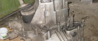
The crankshaft is a complex-shaped engine part, including journals on which connecting rods are attached, from which the crankshaft receives forces and converts them into torque. The crankshaft is one of the most expensive engine parts, so rebuilding the crankshaft may be a more feasible option due to the different design features of crankshafts.
Restoring the crankshaft is a set of operations to restore the bearing surfaces of the shaft, grind the crankshaft journals and replace the bearings.
Before you begin restoring the crankshaft beds, it is necessary to conduct a study of crankshaft defects . Let's look at the types of crankshaft defects that are usually detected when the crankshaft beds are damaged.
Wear of crankshaft beds
The crankshaft in the cylinder block is installed by the main journals in special seats - they are called “crankshaft main supports” and look like this:
In the supports of the crankshaft main journals, liners are installed on which the crankshaft is placed:
The crankshaft main journals are closed from above with covers, into the seats of which liners are also installed:
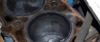
This is what the crankshaft looks like installed in the cylinder block:
Schematically, the crankshaft main journal installed in the cylinder block looks like this:
In this design, there is virtually no metal-to-metal friction - between the surfaces of the liners and the crankshaft journal there is an oil wedge - an oil film that occurs due to the supply of oil under pressure. Oil is supplied through holes drilled in the crankshaft and bearings specifically for this purpose. Despite this, in any engine the liners wear out over time, that is, they become thinner. Because of this, the gap between the liner and the crankshaft journal increases. This leads to a decrease in oil pressure, and as a result, to an increased load on the liner itself and on the crankshaft bed. Ultimately, not only the crankshaft bearing and journal wear out, but also the crankshaft bed. In extreme, emergency cases, the liner rotates in the seat, it blocks the oil supply hole, and all parts located further along the oil supply line begin to suffer from oil starvation. But the seat immediately suffers from rotation of the liner, and quite significantly.
Schematic representation of a worn-out unit:
And this is how the crankshaft main support looks schematically after the crankshaft and liner are removed:
The actual wear of the support looks, for example, like this:
And this is what wear in the cover might look like:
RESTORATION OF THE CRANKSHAFT BED
During operation, the main bearings of the crankshaft experience significant loads, which leads to errors in the shape of the holes in any of the planes within the range of 0.03..0.05, and if measures are not taken to eliminate such defects, then more significant damage occurs during operation:
- deformation of the mating planes in the block for installation of the main support covers;
- deformation of the bearing cap as a result of overheating;
- rotation of the crankshaft liners with the formation of deep breaks and catastrophic wear of the holes;
- destruction of crankshaft bearing caps.
Repairing such holes only by boring does not ensure high performance characteristics, since it is quite difficult to ensure a stable size and the necessary geometric parameters of the holes on all journals. There is a great danger of weakening the hole, there are great difficulties in processing a welded hole or one that has hardening after turning the liners, the high roughness of the treated surface impairs heat dissipation, this is also facilitated by welding with tape and the use of epoxy compositions. Therefore, in order to ensure minimal geometric errors when repairing crankshaft support holes, tight tolerances and the required roughness, honing should be used as a finishing operation.
The machines currently produced abroad for boring the main bearings of the crankshaft are expensive, and if you add tools and equipment for honing, you get a fairly “round” sum. In addition, imported hone heads for restoring crankshaft beds, due to their design features, have a small processing range, reduced radial and axial rigidity, and only expensive imported abrasive stones are used.
In order to restore the crankshaft main bearings to the nominal size with guaranteed quality, Precision LLC has developed a comprehensive technology, producing tools and equipment for repairing the beds of any internal combustion engine blocks with any damage, ensuring all the requirements of the manufacturer.
In all cases, when carrying out repair work, it is necessary to measure paired planes in the block tunnel for installing bearing caps. The operation is performed using a control mandrel and a 0.02 mm probe.
If the non-flatness is more than 0.02 mm, the plane must be processed. This can be done using scraping, on a boring or milling machine, but this is very labor-intensive.
Therefore, the “PRECISION T” device has been developed and manufactured, which makes it possible to mill these planes with the installation of all the equipment directly on the block.
It should be noted that approximately 50% of the blocks received for repair have non-flatness, and if the journals are overheated or a rotation has occurred, then non-flatness in such cases always occurs and can reach 0.3 mm.
The operation of trimming the plane (if non-flatness is detected) when repairing the bed must be carried out necessarily, since when installing the cover on “oblique” planes, the cover and the block are inevitably deformed. Non-flatness on a block almost always looks like this:
When attaching the cover, the block is deformed and begins to experience tensile loads that are extremely undesirable for cast iron, so very often the block after a short period of operation breaks either in the area of the oil channel in the center, or the block ruptures with cracks appearing on the side surfaces of the block.
KAMAZ blocks, on which the power has been increased, suffer greatly from this, but the rigidity of the block remains structurally the same. All this, as well as unacceptable loads, can cause failure of both new engines and engines that have undergone repairs.
LET'S CONSIDER THE MOST CHARACTERISTIC TYPES OF ERRORS IN BIG SUPPORTS AND THEIR PREPARATION FOR PROCESSING:
1. The most common case. The holes on one crankshaft support or on several are deformed due to prolonged alternating loads, as a result of slight overheating or other reasons. The magnitude of geometric errors is no more than 0.1 mm. With such errors, the crankshaft sometimes rotates during installation. But operating the engine with such errors will inevitably lead to more serious damage to the crankshaft bed. In this case, the hole is prepared as follows:
- all bearing caps are settled on an abrasive plate, or on a milling or grinding machine by 0.1..0.2 mm;
- the covers are installed in place, the bolts are tightened to the required torque;
- the holes are measured with a bore gauge. The holes must have a processing allowance in the range of 0.06-0.25 mm. In the area of locks, the size may be within the tolerance of the finished hole.
2. In the event that errors exceed 0.1 mm or it is necessary to replace, for example, the main bearing cap (as a result of breakdown or other reason), the following technology is used:
- “non-original” cover, one or more, is settled by 0.5...1 mm on a milling machine, followed by grinding on an abrasive plate, the rest - - covers are settled by 0.1...0.2 (as in the previous case);
- the covers are put in place;
- The holes are measured with a bore gauge for the presence of machining allowance.
There are often cases when, as a result of overheating, one or more crankshaft support covers are deformed, its edges protrude into the hole by 0.2...0.5 mm and it has a large lateral gap in the block tunnel (V-shaped engines); the surface of the hole in the cover has characteristic blue color. If the cover is based on pins, then the center-to-center distance between the pins in the cover decreases, and it is installed in place with an unacceptably large interference. In this case, the following operations are performed:
- the parting plane of the covers is processed “as clean”;
- the cover (based in the tunnel) is installed in place, the side gaps on each side are determined using feelers, the covers are removed, and the side surfaces are welded (welded with self-shielding wire PANCH-11 semi-automatically without heating the cover and without carbon dioxide), followed by grinding or milling to ensure the necessary fit in the block tunnel;
- The crankshaft support covers (based on pins) are processed as follows: using end gauges, the center-to-center distance of the pin holes located in the block is measured. On a milling machine or boring machine, holes of increased diameter are processed in the bearing cap. The stepped pins are made on a lathe and installed in place.
3. The case when the liners have turned and the hole has a large diameter all around, deep cuts and grooves are visible on the surface. In this case, part of the hole located in the block is welded on, the cover is replaced, and if it is not possible to install another cover, then the cover is also welded on. Welding (in case of strong rotation) is carried out using self-shielding wire PANCH-11 semi-automatically without heating the block and without carbon dioxide. The deposited layer has good adhesion, there are practically no pores, there is no cast iron chill, and it is satisfactorily processed with a carbide cutter.
When the wear is not catastrophic, powder material C-01-11 is applied to the bed or cover by spraying. In this case, DIMET equipment (mod. 405) is used.
4. The case when the holes have a large plus near the plane of the connector (typical for V-shaped blocks). In this case, the covers settle by 0.5...1 mm. Some of the holes adjacent to the connector in the cylinder block are sprayed (welded).
The holes of the crankshaft main supports prepared in this way are used for boring all the journals from one installation, followed by honing.
The prepared bed is processed as follows:
- end plates are attached to the ends of the block and steady rests are installed on them;
- the rollers are installed on the outer supports, but if they are welded on, then the adjacent ones are used;
- the boring bar is placed on the rollers and pressed against them;
- With the help of movable shoes of the steady rests, the position of the boring bar is fixed through the bushings, which is controlled by 4 indicators. The diameters of the rollers are designed in such a way that the axis of the boring bar moves downward by 0.02 mm. If necessary, an intermediate support is installed on the block (to prevent vibration) with a deformation compensator for the boring bar, which, after fixing the intermediate support, is removed from the block;
- indicators and rollers are removed;
- a “bracelet” with a tuned cutter is installed and attached to a boring bar for processing the first neck;
- the hole is bored;
- The “bracelet” is detached and reinstalled to bore the adjacent neck. In this way, all journals are bored in one installation.
Boring can be done by one operator using a PRECISION PP mobile boring drive, or using an electric drill - in this case two operators work.
"PRECISION PP" has a rotation drive through a toothed belt drive from an AC electric motor, a frequency converter for stepless speed control, height adjustment, a two-cardan suspension, a pedal speed switch, is silent and easy to use and can be used in any room with a hard floor. . In addition, “PRECISION PP”, when processing (boring) beds of medium-sized blocks on the horizontal boring machine “PRECISION P3”, is its integral part and can drive the boring bar from any end of the block (cylinder head), depending on the design of the unit being bored.
When boring with an electric drill, one operator holds the drill, the second performs the feed. Boring of welded (sprayed) holes is carried out in several passes.
- the boring “bracelet” is unfastened and removed;.
- the boring bar is removed and the diameter of the holes of all supports is measured; if necessary, the supports with the smallest diameter are re-bored;
- the steady rests, end plates and boring bar support are removed - the block is ready for honing;
- The hong head is inserted into the hole and the bars are opened manually using a key.
The drive during honing is carried out by a low-speed drill through a cardan suspension; rigid expansion of the stones with honing in the nursing mode ensures high accuracy and the necessary roughness. The cutting bars are domestically produced, their durability is 200...300 blocks, after which they are replaced in the consumer’s conditions. The bars are attached to the blocks with epoxy resin.
Honing is carried out with coolant - diesel fuel or working out (only when spraying "DIMET") with periodic watering from a watering can, coolant consumption - 100..200 ml for processing one block.
Adjusting the hong head from one diameter to another is done by replacing the support washers under the support pads. For example, after honing Ø100 (KAMAZ), it is necessary to hone Ø111 (MERCEDES). To do this, you need to place washers 5.5 mm thick. (3 washers for each support block).
Trimming the ends for thrust bearings is done with a tool with a radial feed of the cutter, ensuring the perpendicularity of the processed surfaces relative to the axis of the bed. All equipment is installed and fixed in the already processed crankshaft bed.
The boring time for all journals, for example a KAMAZ block, (without welding) takes 10...15 minutes. If any of the supports are welded, then it is processed in several passes and the time increases accordingly.
Honing time with an allowance of 0.02...0.03 mm is 4...5 minutes.
The total processing time for a crankshaft bed, for example KAMAZ, (without welding) is 2.5...3 hours, and basically this is the time for adjustment, measurements, etc., with welding - 3.5...4 hours.
This technology does not require any special equipment, since all boring equipment (attachments) is mounted on the block. For smaller blocks we offer the PRECISION P3 machine.
As a result of boring using our equipment, all the requirements of the manufacturer are met (ovality, taper no more than 3..4 microns, non-straightness no more than 0.005); the main supports are restored to the nominal size with minimal axis displacement (0.02...0.03 ) and any damage, has been successfully implemented and operated in many large and small enterprises.
The tool and equipment for processing the main supports consists of a hong head (complete with washers for the required diameter) and boring attachments, consisting of:
- boring bar (also used as an installation bar);
- a set of installation rollers for a specific diameter*;
- steady rests with bushings and indicators;
- “bracelet” for installing the cutter anywhere on the boring bar with equipment for adjusting the cutter extension;
- set of base bushings;
- a set of support sectors for a specific diameter*;
- end plates for a specific block**;
- devices for supporting the boring bar and compensating for its deformation;
- tools and equipment for cutting ends for thrust bearings with radial feed of the cutter;
- abrasive plate with measuring equipment;
- auxiliary equipment;
- milling device "PRECISION T" (optional);
- boring drive "PRECISION PP" (optional).
* - positions are individual for each bed diameter
** - positions are individual for each engine model
To process main supports of various diameters, hone heads with ranges of Ø50…Ø65 are manufactured; Ø63…Ø80; Ø78…Ø100; Ø98…Ø130 + special range from 170mm.
Necessary equipment:
- vertical milling machine for milling the side surfaces of covers after welding, milling the parting plane of the cover (for large removals) and boring holes for pins;
- semi-automatic welding;
- set of equipment “DIMET” (mod. 405).
What will happen if the crankshaft bed is not restored?
In principle, if there is damage to the crankshaft bed, it is possible not to do anything with it - just install new bearings, grind the crankshaft to the repair size if necessary (or install a new one), and assemble the engine. But this is bad, and here's why:
- When changing the geometry of the beds, there is a very high probability that the alignment of the main supports will be disrupted. In the best case, it will be so broken that after assembly the crankshaft will not rotate. This is a good option, since in this case the problem will be immediately obvious and will have to be solved one way or another. Otherwise, the engine will start and run, but it will most likely not run for long.
- Even if the alignment is not broken, the problem of a large gap between the liner and the supports will remain. This will lead to poor lubrication of the unit, which in turn will lead to accelerated wear and the need for repeated repairs.
Restoring resolves both problems. The required dimensions of the supports are the main goal of the work, and alignment is ensured by restoration technology.
Thus, the “do not restore” option, although feasible in principle, does not make sense in practice - unless, of course, the goal is to collect the maximum practical knowledge about non-compliance with repair technology. As a rule, the engine is repaired in order to drive, so we can conclude that it is necessary to repair the crankshaft beds if they are damaged.
How can you grind a crankshaft journal by hand?
I had one such case in practice when I polished the connecting rod journal by hand without a machine. Once, relatives came to my friend 1200 km away. How the engine in their VAZ 2114 started knocking when they were visiting because when they went out into the countryside they hit the pan on a stone. The pan was bent and the dent blocked the oil supply to the oil receiver; oil flowed, but very weakly, which is why the second connecting rod began to knock.
They brought me this car on Friday evening, and a friend asks, Sergei, I will help you, but my relatives must leave on Sunday. I tell him that tomorrow is Saturday and the workshop is closed for boring crankshafts, he asks me to figure out how to do it without a machine, I tell him I’ll think about it in the evening and tomorrow I’ll try to do it. During the evening I came up with 10 options, but settled on one, which seemed to me the fastest and most convenient.
I ground the crankshaft journal like this.
I removed the pan without removing the engine from the car, untwisted the knocking connecting rod, looked at the liners, they turned out to be standard, reached into my pile of scrap metal and found some good 0.25 liners. I plugged the holes in the crankshaft journals with a rag, inserted the liners into the connecting rod and coated them well with valve lapping powder, and lightly tightened the connecting rod on the crankshaft journal. I unscrewed all the spark plugs and began to drive the crankshaft with the starter, drove for about two minutes intermittently, again removed the cushion from the connecting rod and again smeared the lapping powder, again pulled the connecting rod cushion, and also began to drive with the starter. I did this until the connecting rod cushion sat completely on the connecting rod, then I removed the cushion and, using a rag in gasoline, removed all the lapping powder from the crankshaft and connecting rod bearings, pulled the rag from the crankshaft journal, lubricated the bearings with clean oil, tightened the connecting rod as expected, checked, the starter turns. I leveled the pan and the oil receiver, put everything in its place, started the engine, it worked great.
The next day, the friend’s relatives went home, and the car did not let them down, and they drove it for another half a year, and then they sold it, and the crankshaft was not repaired.
Methods for repairing crankshaft beds
There are quite a lot of repair technologies; the specific technological route depends on the specific engine and its condition, but we will describe the general methodology.
The first thing you need to understand when faced with the task of restoring crankshaft beds is whether there are liners of repair sizes for a given engine, for the increased diameter of the bed. If yes, and the wear of the beds does not exceed these dimensions, then all that remains is to grind the beds to the repair size. The specific technique will be described below.
If there are no repair inserts, a boring of the nominal size remains. It is also possible that the beds are so worn out that boring to the repair size is no longer possible - in this case, additional metal is applied (spraying, welding), which is bored to the required size.
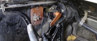
In any case, boring is done on a horizontal boring machine, similar to the one shown in the photo below, but different restoration technologies are used.
Crankshaft device
The crankshaft consists of flat machined plates with counterweights (the so-called “cheeks”), which are connected to each other by “necks”. Counterweights are needed to dampen the reciprocating movements of the pistons and stabilize the rotation of the shaft.
Crank mechanism with an additional block of balancers
In V-twin and W-twin engines, connecting rods from opposing cylinders press against interconnected journals. This allows for more uniform operation of the engine and reduces its dimensions. In in-line engines, each connecting rod is mounted on a separate journal with balancers.
Crank mechanism of an inline four-cylinder engine with standard journals and balancers
V6 engine crankshaft with forked adjacent crankpin
The crankshaft journals are cylindrical in shape with a ground surface. The main journals are located along the axis of the shaft, and the “crank journals” are located along the axis of the connecting rods. The rubbing pairs of the crankshaft are usually mounted on plain bearings. To prevent longitudinal displacement of the shaft, support bearings are provided, they are also called crankshaft half rings.
The crankshaft is located in the cylinder block in the reciprocal seats of the “crankshaft bed”. On the crankshaft there is a shank for fastening the timing sprocket, generator pulley and water pump. On the back of the shaft there is a flange for fastening the flywheel. A rolling bearing is installed in the flange, and the gearbox input shaft fits into it. Inside the crankshafts there are channels for forced lubrication of the journal liners, connecting rods and cylinder-piston group. The design of crankshafts depends on the layout of the cylinders and their number. Drive gears for various equipment, such as an oil pump, can be installed on the crankshaft.
Crankshaft device
Boring to nominal size with lowering of main bearing caps
In this case, about 0.5 mm is removed (depending on the specific case) from the plane where the crankshaft bed cover adjoins the mating part. After this, the covers are installed in their regular places. After this, the bed becomes elliptical, which means it can be cut to the required size.
The sketch shows a lowered cover installed on the main support. The amount of underestimation is exaggerated for clarity:
A clear advantage of this method is the restoration of the nominal size and the use of standard liners. The downside is that the crankshaft axis shifts, and with a large displacement this can be critical for engine operation. As a rule, after measuring the wear of the crankshaft beds, it becomes clear by what amount the caps will have to be lowered and how much the axle will move. Based on this, a conclusion is drawn whether this method is suitable for this particular case.
The sketch shows the crankshaft bed, restored with the cover lowered. Displacement of the crankshaft axis is noted:
This method is not suitable; the engine design uses “explosive” support covers, which are made by the “breaking off” method. In this case, the contact surface of the covers with the bed is uneven. It would have to be lowered by several millimeters, and this would lead to a critical change in the engine geometry, incompatible with its performance.
The photo shows the mating of the cover and the seat:
This is what the mating part looks like:
How to increase the life of the crankshaft
It's no secret that crankshaft boring is an expensive procedure. In addition to the work process itself, you need to disassemble the power unit, which also requires a lot of time and financial costs if you contact the service. The minimum period for performing this repair work will disable the car for several days. In this regard, advice from experienced professionals on how to extend the life of the crankshaft is relevant in any case.
In order to carry out such complex and costly operations as rarely as possible, you need to follow some rules when operating the machine, since the service life of the crankshaft largely depends on the driver and his driving habits.
- Do not allow the power unit to overheat and do not operate the machine under increased loads.
- Replace consumables in a timely manner: filters and engine oil. Use only high-quality parts and materials recommended by the manufacturer.
- Perform any repair work related to the power unit as carefully as possible with the involvement of experienced specialists, provided that you lack personal skills and knowledge.
- Regularly monitor the condition of the crankshaft based on pressure in the lubrication system and oil quality.
Boring the crankshaft beds to repair size
In this case, the bed covers are installed in their regular places without any modifications. After this, the beds are bored to repair size.
The sketch shows the before and after condition:
This, in general, is the best option - it does not lead to a displacement of the crankshaft axis, and in general the engine after it is as close as possible to the “original” state. In addition, the method is also suitable for motors with “breakable” bed covers. As mentioned above, the only downside is that not all engines have repair size liners.
How the crankshaft is bored
Let's start with the fact that boring and grinding a crankshaft with your own hands in a garage can only be done by experienced specialists who have the appropriate set of special equipment. First of all, a crankshaft boring machine must be available, since the entire procedure must be carried out with high precision. It is also necessary to take into account that the complexity of further adjustment of the repair liners will directly depend on the quality of work on the crankshaft.
Also, some car enthusiasts, in order to maximize savings, manage to grind the crankshaft in the garage with improvised means, but this procedure is strongly not recommended, since the result can be completely unpredictable.
Let us add that before starting work, a specialist must check the crankshaft for axial displacement of the connecting rod journals, bending of the crankshaft, etc. At the same time, it still turns out that although shaft repair is a complex turning operation, buying a new part will still be on average 50-60% more expensive compared to how much it costs to bore a crankshaft by an experienced craftsman.
Boring to nominal size after metal application
It also happens that repair sizes of the bed are not provided in principle, and it is also impossible to find something suitable. It also happens that the wear is so great that all repair dimensions have already been “passed”. In these cases, it is necessary to apply (for example, by spraying) a layer of metal, and then bore it to the nominal size. The process is shown schematically in the sketch below:
The technologies described above are sufficient to restore crankshaft beds in the vast majority of cases, and the accumulated experience of Mechanika allows this to be done quickly and efficiently.
Material and manufacturing technology of crankshaft blanks
Connecting rod systems
Material and manufacturing technology are often closely linked. In this case, steel shafts (in order to achieve the highest strength and toughness) are produced by forging, cast iron (the material cannot be forged) - by casting.
Steel crankshafts
Crankshafts are made from carbon, chromium-manganese, chromium-nickel-molybdenum and other steels, as well as from special high-strength cast irons. The most widely used steel grades are 45, 45Х, 45Г2, 50Г, and for heavily loaded diesel crankshafts - 40ХНМА, 18ХНВА, etc. The advantage of steel shafts is the highest strength, the possibility of obtaining high hardness of the journals by nitriding, cast iron shafts are cheaper [ source not specified 199 days
].
The choice of steel is determined by the surface hardness of the journals that needs to be obtained. A hardness of about 60 HRC (necessary for the use of roller bearings) can, as a rule, be obtained only by chemical-thermal treatment (cementation, nitriding, cyanidation). For these purposes, as a rule, low-carbon chromium-nickel or chromium-nickel-molybdenum steels (12ХН3А, 18ХНВА, 20ХНМА) are suitable, and for medium and large-sized shafts more alloying with expensive molybdenum is required. However, recently for this they began to use cheap steels of regulated hardenability, which make it possible to obtain high hardness while maintaining the viscosity of the core. Less hardness, sufficient for reliable operation of sliding bearings, can be obtained by high-frequency hardening of both medium-carbon steels and gray or high-strength cast iron (45..55 HRC) [ source not specified 199 days
].
Medium-sized steel crankshaft blanks in large-scale and mass production are produced by forging in closed dies on hammers or presses, and the process of obtaining the blank goes through several operations. After preliminary and final forging of the crankshaft in dies, the flash is trimmed on a trimming press and hot straightened in a die under a hammer [ source not specified 199 days
].
Due to the high requirements for the mechanical strength of the shaft, the location of the material fibers when receiving the workpiece is of great importance in order to avoid their cutting during subsequent machining. For this purpose, stamps with special bending grooves are used. After stamping, before machining, the shaft blanks are subjected to heat treatment - normalization - and then descaled by pickling or processing on a shot blasting machine [ source not specified 199 days
].
Large crankshafts such as marine crankshafts and tunnel crankcase engine crankshafts are dismountable and bolted together. Crankshafts can be installed not only on plain bearings, but also on roller bearings (connecting rod and main bearings), and ball bearings (main bearings in low-power engines). In these cases, higher demands are placed on both manufacturing accuracy and hardness. Therefore, such shafts are always made of steel [ source not specified 199 days
].
Cast iron crankshafts
Cast crankshafts are usually made from ductile iron modified with magnesium. Shafts produced by precision casting (in shell molds) have a number of advantages over “stamped” ones, including a high metal utilization rate and good damping of torsional vibrations, which often makes it possible to dispense with an external damper on the front toe of the shaft. In cast billets, a number of internal cavities can also be obtained during casting.
The allowance for machining journals of cast iron shafts is no more than 2.5 mm per side with deviations according to the 5-7th accuracy classes. Less stock fluctuation and less initial unbalance have a beneficial effect on the operation of tools and “equipment”, especially in automated production [ source not specified 199 days
].
The straightening of the shafts is carried out after normalization in a hot state in a die on a press after removing the workpiece from the furnace without additional heating.
Oil holes in crankshafts usually connect adjacent main and connecting rod journals and are made by drilling. The holes in the cheeks are caulked or closed with plugs on the threads.