01/25/2022 1,691 Alarms
Author: Victor
Self-repair of the Starline key fob can be carried out in case of any malfunction of the communicator, except for a software problem. Problems of this kind are eliminated by interfering with the operation of the electronic component, so it is not recommended to work with this part without experience. In addition, the recovery process for a device will differ depending on its type - primary or secondary.
[Hide]
General characteristics of Starline key fobs of different models
Main characteristics and features of new remote controls for controlling Starline alarms:
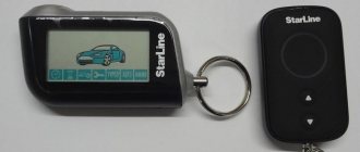
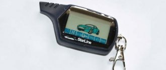
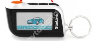
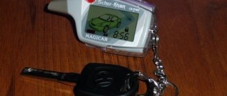
- The anti-theft installation for a car comes with two communicators. Earlier versions used two one-way remote controls; modern models use one pager with a display, the second without. Regardless of the number of keys, the device with a screen has feedback and the ability to monitor the condition of the car.
- The range of key fobs depends on the alarm model, as well as external factors. The latter include the architecture of the area (density of buildings and buildings), weather conditions, battery charge in the pager, and the presence of interference. The appearance of noise can be caused by transformer substations and industrial enterprises. On average, the operating radius of the main remote control is about 100-200 meters, the spare one - no more than 15 m.
- Three and four button devices are powered by batteries of different classes. These can be either ordinary AA batteries or batteries of CR2016, CR2025, CR2032, etc. standards.
- Different models of security systems use different signal encryption technologies. The encoding method can be dynamic or interactive. The second option is more reliable, since the signals sent from the control unit to the communicator and back always have a new code.
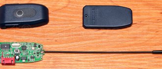
- Starline key fobs can be equipped with built-in or external antennas. This element can be hidden, installed inside the pager and connected via a cable to the main board.
Photo gallery: Starline keychains of different models
Additional keychain Starline B9
Additional keychain Starline A93
Additional keychain Starline D64
Additional keychain Starline A91
Starline B9
Starline A93
Starline E90
Starline B64
Emergency situations and solutions
The following is known about additional alarm key fobs, if the kelloq algorithm is used: they have no feedback. This means that if the owner has lost the alarm key fob, it will not always be possible to find it. The search will be successful if:
- We are talking about basic car key fobs. Use the driver call or unlock the door and look for the source of the sound.
- An alarm key fob with a “dialogue” code, main or additional, is always equipped with a receiver. The search is carried out as described above.
Conclusion: it is better not to lose additional key fobs for car alarms, especially if a “dialogue code” is not used.
Remote control for calling the driver
The bodies of any car key fobs are made of plastic. The body itself usually consists of “halves” held together with self-tapping screws. The external design of car key fobs does not use metal that reflects radio waves. And it’s easier to repair alarm key fobs, no matter what model we’re talking about, the body.
You can quickly change the button module, which is included with the new case by definition. Everything that is said here is relevant to any key fob for car alarms: additional and main.
Repair kit from China
The body of the main car key fobs is always equipped with protective glass. Below it is a display. But if the display is broken, replacing it is very difficult.
It turns out that it will not always be easy to identify an alarm using a key fob:
- The manufacturer does not change the shape of key fobs for car alarms of its models. Which does not apply to third party companies. In addition, if only the body was broken, it could be replaced with a similar but different one.
- Let's say the key fob for the alarm of the required model was not available, and the owner bought compatible equipment. Think about what follows from this.
In general, the key fob alarm is determined incorrectly in most cases. But then there is no need to ask the question why the alarm does not respond to the new key fob. In case of an error, it cannot even be written into the block’s memory. We can conclude that choosing a suitable key fob for an alarm is a non-trivial task.
Various key fobs for car alarms are available at retail, including universal ones. However, the choice must be made with caution. Usually, having purchased several key fobs for a car alarm of the same model, the seller tries to sell them. However, these products may have nothing in common with the alarm key fobs installed in your car except the body. We cannot talk about full compatibility, even if the main unit responds to key presses. Choosing key fobs for car alarms is a separate and not always easy task.
Starline equipment compatibility
Equipment compatibility in Starline anti-theft systems:
- Starline alarm remotes, which have the number “6” in their name, are interchangeable with other similar devices. If the communicator for controlling the E60 system fails, it can be replaced with a key fob from models B64, D64 and vice versa.
- The key fob from the E90 can be replaced with a pager from the B94 and D94, as well as A91, A92, A93 and A94. Accordingly, you can buy an E90 communicator to work with these systems.
- Pagers for controlling Starline A2 and A4 versions are compatible with each other.
- In the Starline 24V, A4 and A2 alarm versions, spare communicators are completely interchangeable.
- Additional pagers are compatible with Starline B6 and B9 security system models.
- Line B alarms have one feature - all models are divided into older and newer classes. The latter are characterized by a blue color in design. Spare remote controls from older versions are completely interchangeable with key fobs from newer models.
- Starline A61 and B6 Dialog communicators are fully compatible. The same applies to the B9 Dialog and A91 models.
Follow-up system check
Upon completion of the repair, you need to check the operation of the security system. To do this, activate the alarm and try to open the door or lightly hit the roof. After this, start the engine by opening the car doors with the key. After starting, the alarm should also go off. Other functions of the security system should also be checked. If everything works and the car alarm goes off, then this means that the repair work was successful.
Checking the car alarm for serviceability
Important! Driving a car with a disabled alarm is extremely risky, as it can be stolen or hacked. Therefore, at the first sign of a system malfunction, it is necessary to carry out diagnostics.
Common faults
The need to disassemble and restore the operation of the device occurs when the following problems occur:
- Failure of the battery or oxidation of the contacts inside the compartment. A low battery will cause the anti-theft system to stop responding to commands transmitted from the pager or to do so unstably. In this case, the display of symbols under the glass will be dimmer, and the blinking color of the LED light will also deteriorate. To restore the device yourself, you need to change the battery, and you will have to disassemble the pager if you need to clean the contacts.
- Damage to the display. This malfunction is usually caused by a serious physical impact on the pager body. In case of critical hits, a protective cover will not be able to save the situation. If the screen fails, the user may still be able to control the security mode and some other options. However, additional functionality will not be available to the consumer, since configuration requires the use of the display in any case.
- One or more buttons on the communicator have fallen off. Over long periods of use, the controls will wear out, which can cause them to stick. If the button fails, to restore the functionality of the key fob, the user will have to disassemble the remote control themselves and carefully check the board. Before replacing the key, you need to purchase a new part. In practice, the cause of the problem is usually a damaged contact on the control element, so re-soldering the button is usually enough to fix it.
- Damage to the pager body. Frequent falls can cause scratches on your device; over time, more serious defects may develop. Keyrings from Starline are generally characterized by low strength, so it is better to prevent them from being hit. The device must be repaired if there is serious damage, since liquid can get onto the board through a crack in the case.
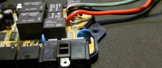
- Hardware faults are usually caused by moisture in the pager circuitry. During prolonged operation in conditions of high humidity, capacitors, as well as other elements of the remote control, fail. Do-it-yourself repair in this case consists of disassembling the device body and drying it. You cannot dry your communicator on a household stove or with a hairdryer, since high temperatures can completely damage it. To dry, it is recommended to place the device in a warm place, for example, on a radiator, for several hours.
Video: troubleshooting the key fob
In a video, user Alexander Shkurevskikh showed the process of identifying problems in the operation of a car pager in the absence of feedback.
Why doesn't the alarm go off?
Malfunctions in the system when the security mode is turned off can be caused by an electronic component or blocking of the power unit.
Problems with car electronics
Possible causes of malfunction of the alarm control unit:
- Software malfunction. To solve this problem, you can try disconnecting the microprocessor module from the power supply and turning it back on after a few seconds. In practice, this rarely helps, but such actions can eliminate a minor glitch, for example, in the operation of a memory unit. If these steps do not help solve the problem, the control unit will need to be reflashed. The task requires special software and skills, so it is better to turn to specialists, otherwise the problem may worsen.
- Long-term operation of the control module in high humidity conditions, which ultimately led to dampness of the board and the formation of mold on it. In the latter case, the electrical circuit changes completely, since it is impossible to remove the plaque without further consequences. If the board is damp, but there is no mold on it, then you can try to dry the device. To do this, it should be placed in a warm and dry place, for example, on a battery, and after drying, installed back. For drying, you cannot use a household stove, open fire or hair dryer, since prolonged exposure to high temperatures will completely damage the board.
- Oxidation of contacts on one or more connectors connected to the control unit. To eliminate the malfunction, the block is cleaned of plaque; when performing the task, you can use a special tool. Traces of oxidation can be removed using a construction brush, the main thing is not to damage the contact elements.
Car engine lock
The only reason is a “conflict” between the alarm microprocessor and the standard engine blocker - immobilizer. The problem usually occurs on systems with automatic engine start. Since the driver is not present in the cabin during remote start, the immobilizer cannot detect the electronic key and regards this as a hacking attempt. As a result, the engine is blocked. To eliminate the malfunction, it is necessary to install a blocker bypass module on the ignition switch.
Video: making an immo bypass module with your own hands
The “Disable the immobilizer” channel in its video talked about how to make your own engine blocker bypass module.
Emergency unlock
The process of emergency shutdown of the security function of the Starline A1, A2, A4 and A8 alarm system looks like this:
- The car doors are opened with a key. If the security mode is turned on, this will activate the siren.
- The ignition is turned on.
- The service mode entry button is pressed three times within the next 20 seconds. For the Starline A8 model, four “clicks” will be required. The service mode button is usually located under the instrument panel, but its location may be different. To find the key, you need to check all the wires coming from the microprocessor module.
- The ignition is turned off. The vehicle security mode should turn off.
In Starline A6 alarm systems, emergency unlocking is possible only using a personal password (standard value is 11):
- The vehicle doors are opened using a key.
- The ignition is activated.
- Over the next 20 seconds, press the button to enter the Valet service mode. The number of “clicks” depends on the first digit of the password - they must match. For example, if the number is 5, then the button is pressed five times.
- The ignition in the car is turned off; to do this, the key in the lock must be moved to the “Off” position. Then it must be immediately switched to “ACC” mode.
- The next number of the password is entered in the same way.
- The ignition is turned off. The security mode should be disabled.
The emergency unlocking procedure for the Starline A91 alarm system is carried out as follows:
- The vehicle door is opened with a key. This will activate the siren as well as external lights. If the number of the latter is 4 pieces, this indicates that the security mode was turned on without the key fob.
- Over the next 20 seconds, the service button is pressed three times.
- The ignition is turned off. Security mode must be disabled. If a personal password is used to control the alarm, it is entered in the same way as in the case of the A6 model. The code combination can include from two to four characters.
The process of emergency shutdown of the Starline alarm depends on its version and is fully described in the service manual for the anti-theft system.
Video: emergency shutdown of the Starline A91 alarm
The Pandora Store channel in its video showed how emergency deactivation of the protection mode is carried out without using a communicator.
Static code
The very first alarms with a radio channel had a static code - each command had its own command packet. The package format was selected by the user or installer using switches inside the key fob, or by soldering jumpers. There weren’t many code options, and you could open someone else’s car with your key fob if the command codes matched.
Such coding did not provide adequate protection; it was enough to write down the “disarm” command and then play it back and the car would be disarmed as if it were a native key fob. Then the first code grabbers appeared, designed to intercept, decode and repeat codes in order to disarm a car for the purpose of theft.
Types of chips with a static code and used in alarm control panels
Types of chips:
- [6010] HT-6010, HT6014, SH-312E - 3-status code
- [H600] HT-600, HT-680, HT6187, HT6270, TT-13, PK-10T - 3-status code
- [5026] AX5026, CT5026 - 3-status code
- [5326] AX5326, AX5326S - 3-status code
- [2262] PT-2262, M3E, CT5062 - 3-status code
- [8092] TT8092 - 3-status code
- [4134] MC41342, MC145026, SC41342 - 3-status code
Using the HT6010, HT6012, HT6014 chips as an example, we will consider the principle of 312 coding (3-status code) and exchange between the remote control and the alarm system. The family includes 3 encoder chips (HT6010, HT6012, HT6014) and three decoder chips (HT6030, HT6032, HT6034).
The code sequence generated by encoders of this family includes a preamble, a synchronizing bit and a 12-bit address/data field, the length of the period of one bit is equal to 6 clock pulses (Fig. 1).
The address and data values on these chips are set using switches, external circuitry, or software. Each address/data pin of the encoder is encoded in three states: connected to the power supply minus (logical zero), connected to the power supply plus (logical one), not connected (not connected) - (Fig. 2).
Brief technical characteristics and compatibility of microcircuits of this 312 family can be found in the table
A typical connection diagram for the HT6012 encoder is shown in (Fig. 3), (A0-A9) - Encodes an address package of 10 bits (access password) (D10-D11) - 2 data bits, resistor (Rosc) - sets the clock chip operating frequency. Data from the output (DOUT) is transmitted to the input of an amplitude modulation transmitter which can operate at a frequency of 433 MHz or 310 MHz
Decoders check the received code sequence, the information part of which consists of 12 bits (N address bits and N data bits). Received data is transmitted to the corresponding output latches only if the command has been correctly decrypted two times in a row and the received address (password) matches the one set in the decoder. If the command is correctly received, a high signal level appears at the VT output. Decoders of this family can have 0, 2 and 4 output data latches (12, 10 and 8 address inputs, respectively). Figure 4 shows a typical circuit diagram for switching on the HT6032 decoder, the information part of which consists of 12 bits (10 address bits and 2 data bits).
Datasheet HT6010 / HT6012 / HT6014 312 Series of Encoders - Holtek (PDF)
Datasheet HT6030 / HT6032 / HT6034 312 Series of Decoders - Holtek (PDF)
How to repair a key fob?
Starline key fob repair may include:
- replacing the remote control battery;
- replacing the case and display;
- restoring or installing new buttons;
- removing dirt and moisture.
For repairs you will need:
- Phillips screwdriver;
- an awl or screwdriver with a thin tip;
- soldering iron with a thick tip;
- copper wire;
- adhesive sealant;
- wet wipe;
- medical alcohol;
- small brush.
Replacing the key fob battery
To change the power source, follow these steps:
- The back cover of the communicator is removed. Depending on the model, this element is attached differently. Usually it is enough to pull the cover down or away from the antenna, but sometimes it is necessary to disconnect a special clamp. If we are talking about a spare communicator, then you may need to unscrew the screws with a Phillips screwdriver.
- The battery is removed from the rear compartment. After this, install a new battery, taking into account the polarity.
- The back cover is being installed in place.
Replacing the body and display of the key fob
Replacing the case and screen of the communicator is done as follows:
- The old battery is removed from the key fob.
- Using a screwdriver, unscrew the bolts that secure the parts of the communicator body. The cover and pager controls are removed.
- If the problem is with the display, then it changes immediately. In the case where a broken screen causes a malfunction of the main board, the circuit is removed. To dismantle the latter, you will need an awl or a screwdriver with a minimal tip, like the one used to repair watches. The board is removed together with the antenna module, and to remove the display you must also turn off the LED backlights.
- Carefully disconnect the graphite cable on the circuit.
- The contact pads on the pager board are being cleaned. A new screen is taken and applied to the remote control body, at this stage the user must ensure that the appropriate display is used.
- Then the wire needles are extended onto the contact legs and soldering is performed. The user must solder these elements as tightly as possible so that during operation they do not accidentally become detached.
- The screen is installed and fixed to the key fob body. The user needs to be careful to avoid any serious physical impact on the display. Glue is used to attach the screen, but if it gets on the display during the process, it must be wiped off immediately.
- The working board is installed in the key fob body.
- The bolts that secure the remote control structural elements are tightened. The operation of the communicator is diagnosed; if all components are working, then power supplies can be installed.
Video about replacing the screen on the Starline A9 remote control
The “Auto Start” channel clearly showed the procedure for replacing the display on the pager for controlling the A9.
Repair or installation of new key fob buttons
Instructions for replacing the alarm key fob controls:
- The back cover of the key fob opens and the battery is removed from the device. There is a small bolt located under the battery; it can be unscrewed with a Phillips screwdriver. If there is a sticker in the battery compartment, it should be removed and checked for screws underneath. Additional bolts are also unscrewed.
- The rear part of the key fob is detached. The user must check the status of the alarm controls. If the buttons are already worn out, they will not be securely fastened.
- The damaged control element is dismantled and put aside. The main part of the communicator is placed on the work surface where it will be repaired, with the display down. When performing this task, you need to be careful with the spring under the housing. This element is used as an antenna, so it cannot be touched when installing a new key.
- The remote control control element is equipped with four contacts, which are installed at the ends. Also on the button you can see two plastic legs without contacts, which are used as guides and are installed from below. Using a toothpick and glue, you need to fix the button, but you must be careful not to fill the contact components.
- After the glue has dried, start soldering the button contacts. These elements are fixed at the corners of the diagram.
- The pager board for alarm control is inserted back into the housing. You need to make sure that all elements are installed correctly and the buttons are secured in place. It is recommended to coat the body components with glue for better fixation. All the bolts on the communicator are tightened, and a working power source is installed in the device.
- The key fob turns on, time parameters and other functions are configured.
Photo gallery: repairing buttons on the Starline key fob
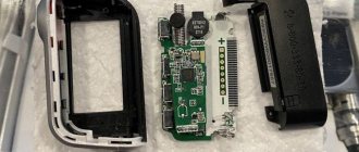
The photo shows a disassembled Starline keychain
Designation of contacts for soldering buttons
Video: replacing the button on the Starline remote control
The Blue Box Ufa channel in its video showed in detail the procedure for replacing controls and soldering them on the Starline pager.
Removing dirt and moisture
Repairing the Starline key fob may involve removing dirt and traces of moisture:
- Using a damp cloth, wipe the body of the communicator. This must be done in order to prevent dirt from entering the device from the outside.
- The rear compartment of the pager is opened and the battery is removed. Use a dry cloth or a construction brush to clean the seat. If there are traces of oxidation on the contact elements for connecting the battery, they must be removed with medical alcohol. First, the liquid must be applied to a piece of cotton wool or napkin.
- The key fob body is being disassembled. To do this, you need to unscrew all the bolts that secure the components of the remote control to each other.
- The inner surface of the cover is cleaned from dirt. For this you will also need a brush or a dry cloth.
- The circuit status is checked. If there are traces of contamination, cleaning is carried out, but you need to act as carefully as possible - do not allow liquid to come into direct contact with the board.
- Then the key fob body is assembled, all steps are performed in the reverse order. After this, you need to turn on the communicator and check its operation.
Recommendations for preventing malfunctions
Tips to prevent your key fob from breaking:
- It is not recommended to store your device in places exposed to moisture or high temperatures. This will lead to oxidation of the contacts on the board, as well as damage to the circuit as a whole, which is why the key fob will have to be thrown away.
- Only working batteries should be used in the remote control, and if the power source fails, it must be replaced immediately. You should not store your communicator with a dead battery. The fact is that after the battery has reached the end of its service life, acid may be released from it. If the battery remains in the remote control, liquid will get onto the board and damage it.
- Do not store the device at low temperatures. If the key fob then gets into a warm place, the frost on the key fob elements will begin to melt and turn into condensation.
- It is recommended to use a protective case for the remote control. It will not protect against serious problems, but it can prevent the negative effects of dust and damage to the device from falls.
Remote control diagram
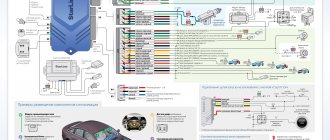
The alarm key fob is a complex radio-electronic device. It is not appropriate to examine the scheme in detail within the framework of this article. If you need to repair it, contact a professional.
The elementary circuit looks like this: the heart of the device is the control chip. It receives signals from the buttons on the key fob, processes them and, through an antenna installed in the body, transmits a specific code at a certain frequency to the control unit of the car. Also, through the antenna, the microcircuit receives a signal from the unit, analyzes and displays information on the screen, or signals with an audio signal. The sound is produced by a miniature buzzer.
Video: DIY repair of the Starline key fob
The AlanMorfreeman channel in its video showed in detail the process of resoldering the contact elements on the communicator to control the Starline alarm system.
Do you have any questions? Specialists and readers of the AUTODVIG website will help you ask a question
Was this article helpful?
Thank you for your opinion!
The article was useful. Please share the information with your friends.
Yes (100.00%)
No
X
Please write what is wrong and leave recommendations on the article
Cancel reply
Rate this article: ( 6 votes, average: 5.00 out of 5)
Discuss the article: