Poor weight on a car leads to poor performance of instruments or a stalled engine. The reason is the loss of contact at the junction of the wire with the car body. This happens due to the end of the bulk wire ending in a copper plate. This cannot be allowed. At the junction of copper and steel, an oxidation process begins, accompanied by deterioration or complete elimination of contact. If moisture gets into the joint or the bolt connecting the terminal to the metal rusts, this can also cause the connection to be interrupted. When there is no contact, this affects the operation of the car.
Symptoms of bad weight on a car
Manifests itself with the following symptoms:
- When you turn the key in the ignition switch, the starter does not turn on, but the relay clicks are heard.
- One lamp on the car began to burn brighter than the other.
- When the turn signal is turned on, another light flashes. The windshield wipers or windshield washers can be activated at the same time.
- There is wheezing in the radio at peak power.
These symptoms make it clear that the contact of the mass has worsened. If it is only broken, then the resistance at the junction increases, accompanied by a deterioration in the operation of devices and units.
Checking grounding in a car
Electronic modules and many electrical components in the engine, transmission and passenger compartment use the body as an electrical ground. This test checks for unwanted resistance at these points, including the secondary ground between the battery and chassis used by some older models. If necessary, consult your vehicle's repair manual.
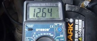
- Connect the black lead of your meter to the battery (-) terminal and the red lead of your meter to where the wire connects to the body.
- Have a helper crank the engine for a few seconds.
You should get a voltage drop of 0.2V or less. If the voltage drop is higher, proceed to the next steps.
- Move the red lead of your meter to the terminal on the end of the secondary ground wire. Take voltage drop readings.
If you get a reading higher than 0.2 volts, proceed to the next step.
- Move your meter's red test lead to the next terminal and ground point. Take voltage drop readings at each point.
When you get a reading around 0.2V or lower, the unwanted resistance is between this and the previous test point. Check for corrosion, broken or loose wires.
Also, check the voltage drop on the ground circuits that connect the engine to the chassis.
Search, check and replace transfer grounds if necessary.
Bad ground on starter: symptoms
Lack of contact directly affects the performance of the brushes. Expressed in relay clicks. The starter will not turn on - the unit does not turn completely. There is no need to rush to disassemble. Check for mass. If the wire connecting the starter to the negative terminal of the battery is broken, it needs to be replaced. Then the starter will work as before.
How to find plus or minus with a multimeter on a car
The wires on the machine are painted a specific color for identification. In some cases, it is not always possible to determine the location of the positive and negative place. Often the problem occurs on Mana because there are many wires coming off the ECU. You will need a multimeter.
- Set the voltage on the device to 20 V.
- Connect the black wire of the device to the socket marked COM. This is the negative pole.
- Insert red into VΩmA. This is positive.
- Connect the probes to the wires whose polarity you need to know.
- When numbers without signs are displayed on the device display, we can conclude that red is connected to the plus, and black to the minus.
- If a dash appears before the numbers, it means the connection happened the other way around.
There are other multimeters where the needle deviates relative to zero. If it is in the positive range, it means the wires are connected in accordance with the connectors. When in the negative zone, the data is opposite.
Troubleshooting
For uninterrupted operation of the battery, the system must be equipped with good quality wires; in this case, copper wires are the most suitable, since they have the best characteristics when operating under voltage.
The thin positive wire coming from the generator must be replaced with a thicker wire.
To protect the existing mass and ensure longer and more trouble-free operation, it is necessary to treat all existing connections and terminal contacts with a special lubricant that has an anti-oxidation function.
You can strengthen the mass by placing additional mass near the generator. Of course, you should not use a thin negative wire to connect to the car body; it is better to use a thick wire. The result will be better, and if problems arise with the main wire, the additional one will be able to start the car, and again you will not have to listen to the clicking of the relay.
As a result of the procedures performed, the car will start more confidently. We will eliminate the problem of frequent battery discharge, which will avoid the loss of much-needed volts for the car and, as a result, ensure the most stable and sufficiently high voltage coming from the generator.
The article was written thanks to the “Crafts” website. This is a creative portal that contains the best master classes on needlework, practical tips on the house, knitting, embroidery, decoupage.
Source
Lada 2112 Custom Car › Logbook › ECU weights
I came across an article by McSystem In fact, here it is below
In January - about Januarys. Again and carefully about the ECM-ECU masses
One of the rather serious problems affecting the smooth operation of engines controlled by the January ECU (7.2, 7.2+, M73, 7.9.7) is the “mass problem” of the ECM. In this case, the matter is not so much in bad (or uncrimped) contacts and their fastenings, but rather in the rather incorrect wiring of the ECM harness itself. And the solution is not in “pulling a prestigious cable (KG-25 or 50)” to the ECU. Therefore, this material will be devoted at a technical level to a competent approach to solving this problem. What is described below is a typical compilation, or an attempt to “chew” what has been published more than once, namely on ChipTuner.ru, and to convey to readers the specifics of solving this problem. The articles by I.N. turned out to be more complete and informative. Skrydlova, (aka Aktuator) “About the masses”, “MASS: AN UNEXHAUSTABLE SOURCE OF GLITCHES” “ONCE AGAIN ABOUT THE MASSES” ©Oleg Bratkov. Many years ago, having read and comprehended what was written, I implemented it on my own car. I agree one hundred percent with the conclusion of the creator (aka Aktuator): “All assurances of the OJSC (form of organization of a public company; joint stock company)
AVTOVAZ is talking about improving the properties of electronic connections in manufactured vehicles, which are not worth a penny. It is almost always possible to achieve normal operation of the engine under the control of the ECM I 7.9.7 and January 7.2 only by carrying out additional work, which is not accepted by the manufacturer as a warranty, to change the electronic circuit of the vehicle.”
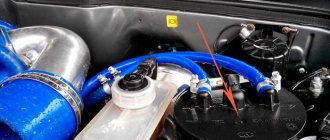
So, on to the topic! Traditional ECM 21124 with ECU January 7.2(+) or M7.9.7 Electronic connection diagram of ECM EURO-2 M7.9.7, January 7.2 LADA 2110 with engine 21124. 21124-1411020-30, 21124-1411020-31.32
Fig. 1 ECM 21124 January 7.2, M7.9.7 Seen, often described and corresponding difficulties - unstable idle speed, freezing speed, “jerking” of the engine at start and operation of the cooling fan, groundless jumps in the electronic characteristics of the ECM during diagnostics. And this is not the entire list. And the whole problem is in the rather incorrect wiring of the masses of the harness, not in relation to the body, but to the ECU. Therefore, in this article you will not see advice on tightening the “hoses” of additional mass to the ECU, due to its complete uselessness. This is not a newfangled “razmasovka” or “razminusovka”... Don’t get your hopes up!
The main idea voiced by the creators is the fundamentally incorrect wiring of the power lines of the ECU and fan and low-current sensor masses. Rice. 12
Fig.2 Ground connections of the ECM. S6, S7, S8
The sensors must be connected to the ground bus of the ECU board and not have contact with the body! There should not be any flow of pulsed and constant currents of the ECU and IM in the mass circuit of the sensors. And the ECU is firmly connected to the body. The rationale is to remove the impact of ECU currents (pulse and constant) and fan current on the reliability of sensor readings. Traditional approach with data collection and processing systems! But not from AvtoVAZ designers, as usual... Now, in order
Fig. 3 Masses according to AvtoVAZ, or how not to create it
1. The ECU masses are combined into three crimps S6, S7, S8, which are combined with each other and with them TWO bends are made for the body studs B3, B4. 2. A switched minus fan with a rated current of 12A is connected to S6, and at the peak at start - all 20A! ! ! Which is {in itself} scary! 3. All this is connected (screwed) to the ECU bracket, which in turn is very flimsily connected to the body. The engine ECM consists of sensors and actuators (AM). Sensors can be easily divided into analog and discrete. Analogue – mass air flow sensor, air pressure sensor, diesel sensor, DD. The output signal of these sensors is a voltage in a certain small spectrum, usually 0 - 5V. For this group, any (even small) interference has a severe impact on the outcome. Discrete - DC (in some approximation), DF, DS (Speed Sensor) - are the least critical to interference, because The output signal has two fixed levels, the highest and the smallest, and the intermediate levels are not interesting to the ECU. Actuators - ignition coils, injectors, canister valve, DC heating, IAC, relays and other sources of huge pulsed and constant currents along the negative (mass) bus of the ECU. To understand what the creators were up to, let’s take a look at the diagram in Fig. 3 – this is a fragment of the main ECM diagram in expanded form. It immediately catches your eye - the masses of the more sensitive and responsible MAF and DTOZh sensors are wired, although there are separate pins for them, 36 and 35, respectively. For what? Silence in response! S6-S7-S8 are connected by jumpers, which further aggravates the situation.
Signs of poor ground contact in KIA Rio 3. We check and fix it ourselves!
During the operation of Kia Rio 3rd and 4th generations, many owners have a very common problem: poor body or engine weight. As a result of high contact resistance, problems may arise with the vehicle's electrical wiring, instability of engine operation, and even problems with starting. There may be several
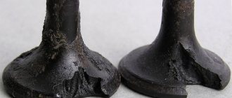
reasons for a bad “ground” – corrosion of wires or terminals (on the body and battery);
– corrosion of the place where the terminals are attached to the body (rust, paint on bolts and threads);
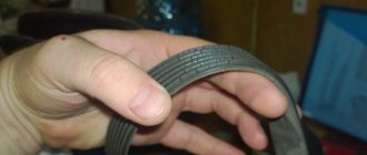
– break in one of the ground wires.
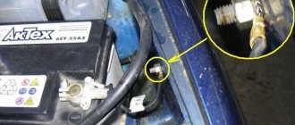
Broken streamer 918604L200 due to improper installation
Signs of poor body and engine mass
For many, poor body or engine weight begins to manifest itself as strange things when operating your Rio, for example, a suddenly dead battery due to an incomplete charge or an unstable idle. The problem may only appear under certain conditions, such as wet weather or winter. Here are some signs of poor vehicle ground contact:
- Increased fuel consumption
- Uneven engine operation
- Problems with starting the engine, especially in winter when higher starting currents are needed
- Incorrect operation of sensors
- Battery not fully charged
- Malfunction of electrical appliances and failure of fuses
- and others
How to check the quality of the “mass”?
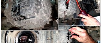
Any check should begin with an external inspection and make sure that the wires are not broken. We check the three main cables: the wire from the battery to the body, the ground wire between the engine and the right “glass”, between the gearbox and the body (located under the engine air filter housing). If there is no external damage, you need to take a multimeter and measure the resistance. We take measurements between the “-” terminal of the battery and the body, engine, in the range of up to 200 Ohms.
Important! Measurements are taken only with the vehicle turned off. Measurements are made only in a de-energized area!
The multimeter readings should be within 1-2 ohms, preferably less. It is important not only resistance at a specific moment, but also that there is good contact at all times, regardless of the weather and time of year. This type of fault must be looked for using more sophisticated equipment, for example, an automotive oscilloscope.
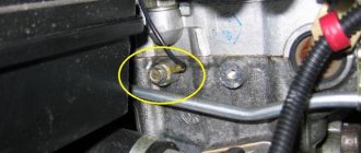
Now we check the connections, the bolts should be well screwed to the body and should not dangle. The fastenings of the terminals to the body must be free of rust, and the terminals themselves must be free of oxides; their condition greatly affects the quality of the contacts.
What to do if the engine “mass” is bad?
If the wires are torn or heavily oxidized, they can simply be replaced; the original wires are quite expensive, so you can choose analogues or buy used braids in good technical condition at a disassembly site, for example, on this site. If the bolts and their mounting holes are rusty, it is enough to replace the terminal mounting bolts and process the threads, removing rust and paint residues from them. With all these procedures, it is necessary to treat all connections and the terminal with a special contact lubricant, which will improve conductivity, reduce resistance and protect against rust.
Rusty earth scythe mounting bolts
Numbers of original wires according to the catalog: Hyundai / KIA 918604L000, “-” battery - body Hyundai / KIA 918604L300, gearbox - body Hyundai / KIA 918604L500 (previously 918604L200), engine - body
The article shows only the main ground cables installed in KIA Rio 2011, 2012, 2013, 2014, 2015, 2016, 2017 model years, but do not forget that many other systems and units are connected to the ground with their own individual wires.
What is engine demining?
Structurally, the car has a developed electrical system, in which the serviceability and accuracy of the controllers, various sensors and many other electrical devices depend on the mass. The electrical ground (minus) is connected from the battery to the car body. The body is conventionally a return wire, forming a closed electrical circuit.