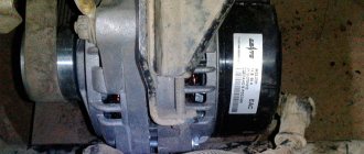
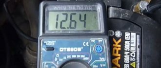
I decided to check the charging during the week! He came home from work, I connected the tester to the battery terminals. At XX, warmed up: 13.72V; at XX with consumers turned on, which he often uses in winter (dimensions with a neighbor, stove on 1st, heated rear window and mirrors, radio): 12.6V. Those. in the first case it is low, and in the second it is too much.
I tightened the alternator belt, and at the same time I thought, let me take on: the ground on the power steering reservoir bracket:
weight on the engine:
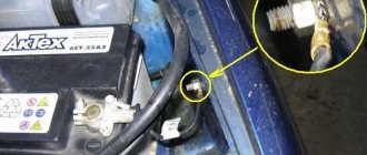
ground from the “-” terminal of the battery to the body:
ground from the “-” terminal of the battery to the engine:
I didn’t touch the other masses, there’s no need and no point!
All these masses and their studs were cleaned of the slightest dirt, cleaned if necessary, lubricated and well tightened. Before this, I did not forget to remove the terminals from the battery, wiped the entire battery, cleaned and lubricated the terminals, also removed the wires hanging on them and also cleaned and stripped if necessary and lubricated, everything was tightened well! There was no result, and there was no time to mess around!
I came to the dacha over the weekend and decided to finish it. I removed the “-” terminal from the battery. pulled out and inserted two generator power circuit fuses F4, F6 (60 A), in the main fuse block:
weight was transferred from the engine (thermostat) to the gearbox stud: from here: here (at the very bottom in the photo):
Result: At idle, warmed up: 13.85V; at XX with the consumers turned on, which he often uses in winter (dimensions with the neighbor, stove on the 1st, heated rear window and mirrors, radio): 13.1V.
If he and I had time, I would borrow a friend’s garage and modernize the gene like mine, installing the RN no. . Everything is great for me, although I haven’t written a report since January 8th of this year, apparently a year will have to pass)))))))))
Source
How to check the ground on a Priora engine
Prior's father has a sedan from the end of 2009, 1.6l 16kl engine, mileage 42,200 km. The configuration with power steering for that year is the simplest, one might say, if you don’t count the Prior with an 8kL engine. I decided to check the charging during the week! He came home from work, I connected the tester to the battery terminals. At XX, warmed up: 13.72V; at XX with consumers turned on, which he often uses in winter (dimensions with a neighbor, stove on 1st, heated rear window and mirrors, radio): 12.6V. Those. in the first case it is low, and in the second it is too much.
I tightened the alternator belt, and at the same time I thought, let me take on: the ground on the power steering reservoir bracket:
ground from the “-” terminal of the battery to the body:
ground from the “-” terminal of the battery to the engine:
I didn’t touch the other masses, there’s no need and no point!
All these masses and their studs were cleaned of the slightest dirt, cleaned if necessary, lubricated and well tightened. Before this, I did not forget to remove the terminals from the battery, wiped the entire battery, cleaned and lubricated the terminals, also removed the wires hanging on them and also cleaned and stripped if necessary and lubricated, everything was tightened well! There was no result, and there was no time to mess around!
I came to the dacha over the weekend and decided to finish it. I removed the “-” terminal from the battery. pulled out and inserted two generator power circuit fuses F4, F6 (60 A), in the main fuse block:
weight was transferred from the engine (thermostat) to the gearbox stud: from here: here (at the very bottom in the photo):
Result: At idle, warmed up: 13.85V; at XX with the consumers turned on, which he often uses in winter (dimensions with the neighbor, stove on the 1st, heated rear window and mirrors, radio): 13.1V.
Engine ground location
Engine mass location
In order to operate a car and carry out repair operations on it, you need to know where the mass is located. Thus, almost all devices and components of the VAZ-2114 require electrical power, and the most powerful consumers are the starter and engine .
Few people know where the ground is located on the engine, since to carry out repair operations it is enough to remove the “minus terminal” from the battery. But, during complete dismantling, and after installing the motor, you need to know where to attach the power.
So, the mass of the body is located on the metal mudguard near the battery.
Location of mass on the body
But, the negative branch consists of 2 wires: thick and thin . So, it is the thick wire that goes to the ground of the body, and the thin one to the closure of the engine circuit. Of course, not all motorists know where it goes.
The negative wire of the VAZ-2114 engine is located on the cylinder head and is attached to the tightening bolts that hold the cylinder head plugs.
Location of the VAZ-2114 engine mass
Dashboard indicator symbols
| 1 | Tachometer. The device measures the engine crankshaft frequency (revolutions per minute). If the arrow goes beyond the red value, it means that the Lada Priora engine is operating in a dangerous mode; |
| 2 | Brake force distributor indicator. Reports defects in the operation of this node; |
| 3 | Battery charge. If the lamp lights up while the engine is running, the battery is discharged; |
| 4 | Left turn signal. The sign flashes when there is an alarm or the left indicator is on; |
| 5 | Speedometer. The device reports the speed at which your Lada Priora is currently moving; |
| 6 | Emergency lubricant pressure in the engine. If the sign lights up during operation of the power plant, it means the pressure in the system is low; it is highly not recommended to operate the engine in this condition; |
| 7 | Right turn signal (see No. 4); |
| 8 | Handbrake indicator. Lights up yellow if the Lada Priora is in the handbrake; |
| 9 | Antifreeze temperature in the cooling system. The operating temperature of the motor starts from 90° and above to the red mark. If overheating occurs, turn off the engine; |
| 10 | Gasoline level in the tank. If the fuel level approaches the minimum, the fuel pump may break; |
| 11 | Reserve gasoline level. The indicator lights up when there are less than 10 liters left; |
| 12 | Key for resetting the daily mileage and switching between display modes; |
| 13 | Alarm. If you have triggered the emergency lights, the lamp will flash along with the turn signal arrows; |
| 14 | Malfunctions in the electric amplifier. If defects appear in the EUR, the lamp will light up while the engine is running; |
| 15 | High beam designation. An active indicator indicates that you have switched to distant; |
| 16 | Outdoor Lighting. The system notifies the driver about the operation of the headlights or low beams; |
| 17 | Airbag malfunctions. If the lamp lights up after starting, then there is a high probability that the airbags will not deploy in a collision; |
| 18 | Immobilizer. An audible signal and flashing indicate that the immobilizer system is faulty; |
| 19 | Computer screen. Here you can view information from the bookmaker, as well as find out the total and daily mileage; |
| 20 | Indication of unfastened seat belts. The buzzer will signal a violation for 90 seconds; |
| 21 | The brake system is in disrepair. Most often these are worn pads or insufficient fluid in the system; |
| 22 | Disabling a specific airbag; |
| 23 | Indicator of defects in ASB operation, the braking system is operating normally; |
| 24 | Check Engine – there is a breakdown in the engines; diagnostics and subsequent repairs are urgently required. |
Removing the instrument panel
We carry out work to replace the instrument panel, panel wiring harness and elements of the heating and ventilation system. Disconnect the wire terminal from the negative terminal of the battery. We remove the steering column switches (see “Removing the steering column switches, switch connector and spiral cable drum device”). Remove the cover of the fuse box (see “Replacing fuses and relays”). We disconnect the wire blocks from the ignition switch (see “Removing the ignition switch, replacing the contact group and immobilizer coil”). We disconnect the wire blocks from the electric power steering control unit (see “Removing the steering column”). Remove the floor tunnel lining (see “Removing the floor tunnel lining”). Overcoming the resistance of plastic latches...
...remove the left front pillar trim. Similarly, remove the upholstery of the right front pillar.
Using the blade of a slotted screwdriver, placing soft material under it, pry off the glass blower nozzle of the left door. Similarly, remove the blower nozzle on the right side.
Using a 10mm socket, unscrew the nut for the upper fastening of the instrument panel, located in the cavity under the door glass blower nozzle. Similarly, unscrew the nut on the right side.
Using a 10mm socket, unscrew the bolt securing the ground wire ends of the instrument panel.
We disconnect the wiring harness connectors of the instrument panel from the wiring harness connectors located on the bracket above the fuse mounting block...
...and the wire block located on the right end of the bracket.
Disconnect the engine control wiring harness block from the instrument panel wiring harness block...
...and use a 10mm head to unscrew the nut securing the end of the ground wire. We disconnect the middle block of the instrument panel wiring harness from the electrical accessories control unit (see “Removing the electrical accessories remote control system controller”).
The exclamation mark is on - what to do?
We have noticed that new topics often appear on car forums where drivers ask about the exclamation marks that are displayed on the Lada Priora panel. They rarely specify where it is lit and what is depicted on the icon. In this section we have collected a small FAQ Below are all the exclamation marks that can light up on the instrument panel of a VAZ 2170 car. The designations of these icons are as follows:
The red exclamation mark in the circle (bottom) is lit. The indicator indicates that there is a problem with the vehicle's brake system. This is usually a low brake fluid level. Add it to the tank and, most likely, the sign will stop lighting. If this does not happen, then it is worth checking the system for damaged components. When igniting, the indicator lights up for 4 seconds and then goes out. The red exclamation mark in the triangle/circle (above) is lit. Modern versions use a triangle instead of a circle. The indicator tells us about defects in the operation of the brake force distributor
Use extreme caution if the light comes on while driving. Exclamation mark near the steering wheel icon
When illuminated for a long time, it indicates a malfunction in the electric power steering (EPS). Like other icons, it lights up when ignited and goes out after a few seconds if the system is working properly.
ECU weight
How the mass of the ECU works, how to check the mass of the ECU, what problems may arise and how to modify it to avoid troubles in the future.
It is these very important questions that we will address on this page.
A reliable ECU ground is very important for the proper operation of the engine management system and the engine as a whole.
It would seem to be a primitive and reliable design that can serve well for years. But in reality this is far from the case.
It is very difficult to list all the possible problems that can arise due to poor ECU mass, since it can affect anything. But the main problems can be divided into two points:
Ground points in the car interior
- GND7 - ECU ground
- GND8 - ground on the engine panel
- GND6 - ground above the fuse box
- GND5 - tunnel mass
At the rear of the car, the “grounds” are located near the lights:
Engine demining and signs of poor grounding
An electrical circuit needs a good ground to function properly. Many people ask - why is engine demining necessary? The answer is - poor electrical grounding can affect one or more electrical systems, because it forces the current to look for other simpler paths. This can cause all sorts of problems with lights, sensors, modules and other electrical and electronic components, all of the above is also true to answer the common question - what is the purpose of mass in a car.
The ground on the car is missing: what does it mean and how to fix it?
“The “mass” has disappeared!” – this is the spell we most often hear when contacting auto electricians with any malfunctions in the electrical equipment of the car. What is useful to know about the “mass” in a car, and how to fix it yourself if it disappears?
Two wires or one?
To connect the payload to a power source, two wires are required - even a schoolchild knows about this (although Nikola Tesla thought otherwise...). The most obvious example, quite possibly the one right next to you right now, is a table lamp plugged into an outlet. The few consumers of electricity on the first cars of the late 19th and early 20th centuries were switched on in approximately the same way. The scheme is simple, reliable and quite viable.
However, as soon as the production of cars became at least somewhat widespread, the commercial thought of industrialists immediately went in the direction of economy and optimization, and the number of wires in the car was immediately halved - the metal mass of the body began to be used as one of the wires - in common parlance the same “mass” "
The extremely simplified, but quite clear picture above on the right shows a modern car electrical circuit - when the “ground” is the negative wire of the on-board network. However, this was not always the case... Until approximately the 50s of the twentieth century, automakers used both minus and plus as “mass”.
Standards in the automotive industry had not yet been established, and from an electrical point of view there was absolutely no difference whether to run a plus or a minus on the body. However, by the middle of the century, observations revealed more noticeable corrosion damage to the bodies of those cars in which the “mass” was precisely a plus! It turned out that in this case, electrochemical corrosion develops more intensively, due to the direction of movement of electrons in the electrical circuit - from plus to minus. As a result, the plus “mass” was universally abandoned in favor of the minus one – especially since this did not require the slightest additional investment in production.
Replacing a plus with a minus
Among the models of the domestic automobile industry, the plus on the “mass” was found in Pobeda, in Moskvich 401-402 and earlier, in the first release of the “21st” Volga (since 1960, the electrical equipment system of the GAZ-21 was changed to the traditional one for our days). A car in the USSR was a very durable product, passed down from generation to generation for decades, and after it became known about the harmful influence of the positive “mass”, a fair number of owners of old Muscovites, Pobeda and Volgas began to independently alter the polarity in the electrical system of their cars. Moreover, in the literature for motorists of that time there was a lot of advice and recommendations for such an upgrade.
Where is the ECU ground located?
The ECU mass is usually arranged like this. The engine control unit housing itself is screwed to a metal bracket, which, in turn, is screwed to the car body. Also, a separate ground wire is removed from the ECU connector, which is connected to the engine via the starter mounting bolt.
Everything is simple and reliable. But in reality, over time, the voltage begins to drop in this section of the circuit, slowly but surely, disrupting the operation of the system.
This article is a logical continuation of the previous article, where we checked the voltage drop in the ground circuit from the engine to the body. I advise you to familiarize yourself with it first, and then continue to implement the modification given below in this article.
In general, last time we found a voltage drop in the ground circuit from the engine to the ECU
And on this page we will solve this problem by laying additional mass from the ECU to the engine and from the generator to the body.
We will look at the mass from the generator in another article very soon (I’ll give a link here), and on this page we will focus on the additional mass of the ECU.
What could happen to the car due to poor ground contact?
With the electrical equipment of any vehicle, malfunctions can occur that seem to people far from electricians to be the work of evil spirits. And the culprit of mysterious malfunctions in the electrical equipment of a motorcycle or car, in most cases, is poor contact of the negative terminals - “ground”. But let's take things in order.
Many drivers know that the method of connecting electricity consumers to a power source (generator or battery) on any vehicle is single-wire. The second (negative) wire is the body of a car or the frame of a motorcycle (trike, scooter, ATV, etc.). The very idea of connecting the negative side of a power source (battery) to a steel frame or body is quite old and natural, as it can significantly simplify, lighten and reduce the cost of any vehicle.
A separate ground wire is used to connect the engine to the body or frame, since the engine hangs on rubber mounts that do not allow current to pass through, while both plus and minus are required by the starter, and, for example, by the carburetor solenoid valve. On foreign cars, especially injection ones, there may be even more consumers requiring electricity (and, accordingly, plus and minus). But the positive wires usually begin and end with quite reliable terminals, which are usually in completely sealed plastic blocks or rubber covers, but the negative wires are attached to the body or frame according to the principle “some water will find a hole.” And the body itself, in the place where the hole is drilled and the negative wire is secured, begins to rust very quickly, unless, of course, appropriate measures are taken immediately.
In addition, many do not take into account another important fact, which is known even to a novice electrician: aluminum and copper terminals cannot be connected to each other, since these metals, to put it mildly, are “not friendly” with each other, and begin to oxidize intensively. How can oxidized parts have normal contact? But I often see on the vehicles of inexperienced drivers, on the aluminum housing of the gearbox or engine head, a screwed-on copper terminal of the negative wire, which, in addition, is also washed by streams of water in bad weather.
A steel body or frame is also not friendly with copper, like aluminum, and forms an electrochemical couple. And the saddest thing about this is that the steel in such a connection will be blown away by two people and will corrode several times faster. As a result, the contact disappears (or there is a significant loss of current). Standard terminals installed at the factory are usually tinned. But under a thin layer of tin, which is easy to tear off when installing the terminal, there is still the same copper alloy.
Based on the above, it is obvious that the negative connections themselves to the body or frame are initially less reliable than the copper wires themselves and their copper terminals (tips). Now imagine, for example, in order for electricity to reach the carburetor solenoid valve, the electric current must go along a copper wire (copper bus) from the battery to the body, then along another wire to the engine, then along the intake manifold studs and their threads, often coated with sealant (or the studs are rusty), and finally go along the threads of the solenoid valve itself. Loss of contact in any of the listed places - and the circuit is open, and hence a whole bunch of malfunctions. As a result, the inexperienced driver is surprised - why did the carburetor suddenly begin to work poorly and gasoline consumption increase? You need to go to a carburetor specialist or buy another carburetor. But usually few people know that in such a situation the carburetor has nothing to do with it. And I gave one example of a sudden malfunction, but there can be many of them.
Therefore, in modern cars or motorcycles, full-fledged negative wires are increasingly used, because modern on-board electronics will not work without them, and most devices or programs will fail. On such equipment, reliable contact is especially important. Experienced electricians know, and I have already said this: in electrics there are only two faults - there is a contact where it is not needed, and there is no contact where it is needed.
Typical malfunctions on a car due to poor ground contact (but not all, we read about the rest below) .
These malfunctions, as I already said, seem like miracles to inexperienced drivers. It is not uncommon at a factory (especially a domestic one) to place the negative terminal of the headlight on a stud or bolt securing the headlight housing to the body, and then tighten it with a nut. At first glance, many will think that everything is correct, because the stud or fastening bolt is welded to the body. But the headlight housing is made of soft plastic, and the nut on the terminal cannot be tightened properly, otherwise the plastic will crack. In the end, it only takes a short drive on our roads to weaken such contact to the point of its complete absence. But in a standard headlight with a modest lamp of 55-60 watts, the current consumed even by such a lamp is quite large - up to 10 amperes (if both its threads are energized, both high and low beam).
In the end, a bad contact, if it does not disappear completely, will burn out, the resistance of such a connection will increase even more, and from a school physics course we know that the greater the resistance, the more heat is released when current passes in this place. This means that the burning of contacts will intensify even more (a vicious circle), and it’s not far from a fire (plastic burns well). And many young novice drivers, instead of a standard 50-60 watt lamp, install a hundred (100 watt), which consumes even more current. The consequences can be dire.
Do-it-yourself dashboard tuning on Priora
Torpedo of a Lada Priora car
The dashboard on the Lada Priora has improved characteristics compared to previous models of the domestic automobile industry. When creating it, “soft look” class plastic was used, which looks like good leather and is scratch-resistant. The same material, in addition to the dashboard, is on the upper trims of the door trims. The new Lada instrument panel in the “luxury” configuration may have a number of parts decorated with black varnish.
The panel on the Priora has a large display with touch control, which displays auxiliary and external information, in particular: the navigation screen, settings from the multimedia system, parameters from the trip computer, etc. Experts note that the instrument panel computer is maximally adapted for Russian users, i.e. - information is transmitted in Russian.
Additional ECU weight
We will try to do this within the budget. Therefore, I immediately want to dissuade you from adding additional mass to the ECU using special wires for mass and all kinds of copper braids. And I see three reasons for this:
Therefore, I think that the ideal option is a regular wire with a cross-section of approximately 4 sq. mm. Actually, this is the path I followed.
Using the example of a Chevrolet Lacetti with a Sirius D42 control unit, we will need:
The whole thing cost 30 UAH.
Disconnect the negative terminal of the battery
Now you need to use a 12 mm wrench to unscrew the nut securing the negative wires to the starter bolt
This is not as difficult to do as many people think. Yes, everything needs to be done by touch, but it is quite possible. I have unscrewed this nut a huge number of times, so I can do it in one minute without any problems. Believe me, the eyes are afraid, but the hands do! Or rather, in our case, the eyes don’t see, but the hands do
Has anyone done additional masses for the generator and battery and will it be any good?
Has anyone done additional weights on the generator and battery and will it be any good??
Good evening ladies and gentlemen
by Adminrive · Published 09/08/2014
I haven’t looked in stores for so long
by Adminrive · Published 12/29/2014
Has anyone struggled with the gasoline vapor recovery system?
by Adminrive · Published 01/27/2017
- Comments 13
- Pingbacks 0
Will. Plus duplicate.
If you do, you won't regret it! Buy kg 35 or 25
Of course it will be helpful. 50 kV is better to take the wire straight away.
will be stretched + from the genes with a cable of 25 kg and weight, it sags much less when the windshield heating is turned on, previously there was a drawdown of 1 volt
Description of the dashboard
The dashboard contains the following elements:
- Unit for controlling instrument lighting and external lighting.
- Horn switch.
- Switch for turn signals and headlights.
- Instrument cluster for Lada Priora.
- Lever for glass washer and wiper.
There is also an ignition switch on the instrument panel, which is combined with an anti-theft device. On the Lada Priora it has three positions. In addition, the instrument panel contains buttons and mechanisms such as a heated switch on the rear window, a clock, an alarm switch, a glove box lid, a tape recorder socket, an ashtray, a fan control unit, etc.
Tuning for the dashboard (dashboard) can be done with your own hands if you want to change the lighting for the instruments. In this case, the panel must be removed. The answer to the question: “How to remove the panel?” quite simple - using a screwdriver. Then we unscrew the fastening screws, disassemble the panel, remove the hands (you can use a knife, placing a piece of cardboard on the dial), and separate the cover from the plexiglass.
Replacing the dashboard backlight is done by scraping off (with a knife) the coating on the gasket numbers. If you want to leave them white (brighter), then you can put all the elements back together. However, many drivers want to make the instrument panel more informative. To do this, take a not very thick plastic bag with colored designs, from which parts of a certain color are cut out and glued to the back of the instrument panel. This way you can highlight, for example, areas of high speed on the speedometer, or “cold” areas on the temperature scale.
How to maintain vehicle ground points
Poor contact will affect the operation of electrical appliances. Most often these are large-scale failures or “glitches” of the vehicle’s electrical equipment. To prevent this, you should monitor the condition of the mass attachment points:
Have you ever encountered problems with your car's electrical system when the cause was a bad ground? Let us remind you that other operating instructions for Vesta can be found in this category or in the contents.
I decided to check all the masses, clean the connections and duplicate + and - to the battery. Let's start with something interesting - Cleansing the masses. I found only 4. We also find them, take sandpaper 200 - 400 and go:
— The first and most important one is located near the battery, behind the headlight. The backup KG-35 was attached there. — The second one is on the head near the air vent — The third one is behind the left headlight — The fourth one is on the ECU mounting bracket
Cleaned everything up and tightened it securely.
The duplicate KG-35 goes from the gene to the battery (+) and from the body to the battery (-) This did not fix the problem with the sensor (I will calibrate it tomorrow) But the voltage has increased, engine starting has become faster and... it seems that the car drove a little more fun
About the masses
Text and photo: I.N. Skrydlov, Lyubertsy (aka Aktuator)
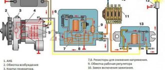
Nowadays, the vast majority of vehicles use the vehicle body (vehicle) as a common wire for the majority of electrical consumers. The body is therefore called the mass (foreground, ground) of the car. If any of the connections to the mass becomes unreliable, miracles begin. The simplest example of this is the blinking of all the lamps in the rear light. We turn on the turn signal, and it starts blinking with the brake light or reverse light. At the same time, at the required consumer, the voltage is two to three times different from the required 12 - 14 volts, and at the unnecessary (not turned on), on the contrary, quite sufficient voltage appears for its operation. This is with light bulbs. What if this starts in the Electronic Engine Control System (ECM)? Then the engine may begin to spontaneously change its operating mode - from gaining high speeds to stalling.
I’ll try to describe the places where the loss of a reliable connection to ground is most likely, and the glitches that appear in this case. I ask you to forgive me in advance for the sometimes strange and unusual names of components and car parts, but since I work at a VAZ warranty station, the situation obliges me.
I'll start, perhaps, with the Rechargeable Battery (AB). In modern VAZ cars, a double wire comes off the negative terminal of the battery. Its thick part, about the thickness of a little finger, connects the negative battery and the engine. If the contact of this wire is unreliable, there may be a deterioration in the battery charge, a decrease in the starter rotation speed when starting, as well as problems in the ECM system, because the minus comes from the engine, from the studs on which the ignition distributor hung on carburetor cars. First of all, you should check the tightness of both nuts, between which the wire tip is attached to the engine. First, loosen the outer nut, tighten the nut under the tip, and then tighten the outer one back.
The thin wire connecting the battery negative and the car body is the main connection for all electricity consumers in the car, and in carburetor modifications also for the engine. You should check the tightness of both the M6 bolt directly on the battery terminal and the M8 nut on the body. The location on the body depends on the make of the vehicle.
| . | . | . | ||||
| VAZ 2110 | VAZ 2108 – 99, 13 – 15 | VAZ 21213 | VAZ 11183 | |||
| Chevrolet – Niva | Priora - battery | Priora battery mass on the body | Protection of main power circuits on Priora |
ECM grounding points
Family 2108 – 9 and 13 – 15 1.5L the mass of the ECM is taken from the engine, from two M6 bolts securing the plug on the right side of the cylinder head. For carburetor cars, the ignition distributor was attached there. Family of cars 2113 - 15 1.5 and 1.6L with new generation controllers Bosch 7.9.7 or January 7.2, the ECM connection to ground is located on a welded pin that secures the metal frame of the central console of the instrument panel to the floor tunnel, through a metal strip with two side lugs on the left and right (Inside the center console, approximately under the ashtray). Unfortunately, as practice has shown, there is no
. Because of this, given that the stud itself is painted during the manufacturing process of the vehicle, and is practically not tightened with the corresponding nut, over time, a voltage drift appears in the ADC channels of the DTOZH, TPS and MAF sensors when the radiator electric fan is turned on. As a result, we have a jump in engine speed when the fan is turned on. Treatment options are described in the FAQ . Thus, in this case, poor electrical contact between the body and the battery negative is also very critical. (See above).
Family 2110-12, 1.5L . The ECM weight is taken from two M6 bolts located on the left side of the cylinder head. Family 21114, 21124 1.6L , with new generation controllers Bosch 7.9.7 or January 7.2. There is already one M6 bolt in the head. The ground is taken from it only for all four ignition coils, and the ground for the ECM is taken in the cabin, from the welded stud on the ECM mounting bracket, behind the left screen of the center console. In turn, the mass is supplied to the bracket through a pin welded to the engine shield in the middle. The nut on this stud is usually not tightened. If there is insufficient contact in these connections, voltage drift in the ADC channels of the DTOZH, TPS, and MAF sensors is possible when the radiator electric fan is turned on. As a result, we have a jump in engine speed when the fan is turned on. Treatment options are described in the FAQ . Thus, in this case, poor electrical contact between the body and the battery negative is also very critical. (See above).
Niva family with Bosch MP 7.0 controller. The mass of the ECM is taken from the engine, from the bolts securing the plug, in place of the ignition distributor - distributor, next to the ignition module.
Niva family with Bosch M 7.9.7 controller. The mass of the ECM is taken, which has already become typical for the new generation of controllers, from the car body. In this particular case, directly from the studs of its fastening. However, I personally didn’t really like this method due to the fact that the terminal crimped at the end of the wire is much thicker than necessary for the castle washer to be evenly pressed against the car body around the stud. Therefore, I left the washer in place between the body and the controller, but moved the terminal directly under the controller mounting nut.
On Niva 21214, the mass is taken from 2 sides of the block. Next, both wires enter the common harness and go to the ECU connector. In front of the connector there are twists for each brown wire where the mass is distributed for the remaining sensors and the ECU itself.
Chevy Niva family with Bosch MP 7.0 controller. The ECM ground is taken from the engine block, from the M8 studs located in its lower left part, under the ignition module. In the photo above it you can see the mounting studs for the MZ (it has been removed).
Family 2104-07 “classic” with old controllers. The ECM weight is taken from the bolt that tightens the bracket securing the ignition module to the engine block.
Family VAZ 11183 "Kalina" . The ECM ground is located on the right side of the engine, on the intake manifold mounting bracket.
Grounding points for electrical equipment (torpedo harnesses)
For families 2108 - 9 and 2113 - 15, the only connection point between the torpedo harness, the rear harness and the circuit of the mounting relay and fuse box is on the steering shaft mounting amplifier, under the instrument cluster. If the contact in this connection is unreliable, deviations of the arrows of the temperature and fuel level indicators are possible when the side lights, direction indicators, sound signal, windshield washer, windshield wiper and other consumers are turned on. For the lazy “diagnostician type” in the 2113 – 15 family, it is possible to throw the “snot” from the mass of the cigarette lighter onto a metal structure inside the center console of the instrument panel - the “beard”, with a wire with a cross-section no smaller than that going to the cigarette lighter. But only if the factory instrument panel is installed. This can be determined by the presence of a fastening of the specified metal structure to the floor tunnel, a “proprietary” fastening of the ECM controller - using a plastic adapter between the controller and the metal structure and a fixed diagnostic connector in the standard place behind the decorative plug under the ashtray. For conscientious diagnosticians: be sure to securely tighten the standard bolt after removing the instrument cluster. The same family has another ground connection, the heater electric motor. It is located under the instrument panel, on the left side of the heater housing.
For the 2110-12 1.5L and 21114, 21124 1.6L families, everything is different. There are more such connections there. The first ground connection of the vehicle is located inside the instrument panel, on the top left of the relay and fuse mounting block, under the sound insulation. On cars of the first years of production, the ground wires to the welded stud were approached on top of the sound insulation, and then someone’s bright mind came up with the idea of hiding the wires under it. So access to the stud is very inconvenient and is only possible using a tube wrench or an extended 10-mm socket. If there is insufficient connection in this place, when you turn on the headlights or electric window motors, the windshield wiper and washer may turn on, and the central door locking system may work.
The second connection is located on a welded stud, on the center console of the instrument panel, on the left side, above the left console screen, under the M6 nut. But even if this nut is tightened properly, and the problem remains, then we move on to the most important point of mass for the entire instrument panel, grounding the entire metal frame of the panel. This is a welded stud with M6 thread. It is located on the lower, inner (cabin) side of the engine shield, in the middle. The nut screwed onto this stud also secures the bracket that secures the front part of the left screen of the console, which some diagnosticians and electricians mercilessly remove due to the fact that there are frequent cases of damage to the ECM harness or central locking system on this bracket. As a rule, the nut is tightened very, very mediocre. If there is insufficient contact in this and the previous connection, when turning on the side lights, headlights and radiator fan motor, deviations of the temperature and fuel level indicator arrows are possible.
In the NIVA family with all types of controllers, the mass of the torpedo harness is attached with a nut to the welded pin for fastening the relay bracket, and, as has become customary, it is tightened very loosely. This pin is located behind the standard fuse block. The mass of the engine compartment harness is attached to one of the welded studs securing the brake fluid reservoir. The mass from both radiator cooling fans is also screwed there.
In a Chevy Niva , the main connection point of the harnesses to ground is in the upper left part of the engine shield on the passenger compartment side, also on a welded stud. To access the connection, you need to unscrew the decorative cover covering the mounting relay and fuse block and this block itself. Another problem area of the Chevy Niva is the power mass of the battery, which is screwed to the body next to the chain tensioner.
There are also 2 ground wires on the ECU mounting bracket. In the photo, the ECU has been removed for clarity.
In the VAZ 2104 - 07 “classic” family , the mass of the torpedo harness is attached to a welded pin behind the instrument cluster, along with the turn relay.
I would also like to note this important detail: absolutely all the studs to which the ground wire terminals are attached are painted at the factory along with the body; they do not have any protective coating other than a layer of paint and are therefore susceptible to corrosion when the paint is removed and there is no additional protective lubricant. To ensure proper contact of the specified terminals with the body, the factory uses them , which, unlike Grover washers, should not be between the terminal and the nut, but between the body and the terminal. With its sharp edges between the cut-out teeth, the washer with one side facing the body pierces the paintwork, and the other side facing the terminal firmly digs into it. The correct location of these washers should be the first thing to pay attention to when clients contact us about faults in electrical equipment after performing reinforcement work carried out during the process of tin-painting or other repairs. In particular, when removing the bracket for fastening the air intake hose on the tenth family, which sits on the stud fastening the negative battery wire to the body, the specified washer must be located between the body and the bracket.
In conclusion . If you have found a place with poor contact, take the time to separate all connections from each other, identify burnt or oxidized areas, and thoroughly clean and level all contacting surfaces before final assembly.
Below is a small gallery of connecting mass power points on domestic car engines.
| . | . | . | ||||
Changes in the fastening of the “battery ground – body” wire on the VAZ 21124
Around November-December 2005, the method of attaching the air intake and ground wire was changed. Air intake
M6x15 bolt with a washer through the hole in the body. The bolt is screwed into the welded nut of the air intake mounting bracket. The method of fastening the battery ground wire to the body has been changed, in terms of fastening to the vehicle body. Now it is attached to a welded pin M8x20, located between the battery platform and the left headlight of the car. Together with it, the electrical ground wires are attached to the same stud. radiator cooling fan and the mass of the left front wire bundle.
On the same topic:
Addition to the article from the author: About the masses. part 2.
Material on this topic from Oleg Bratkov: Again about the masses.