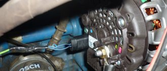
The performance of the generator device is primarily reflected in the operation of all electrical equipment in the car. This unit consists of many parts, so even the breakdown of one part can cause the entire unit to fail. How to properly maintain a Gazelle generator, what you need to know about diagnostics and how to change brushes correctly? We will talk about this below.
Technical characteristics and principle of operation of the generator set
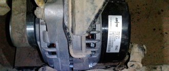
Gazelle 402 and 406 cars are equipped with generator sets, which are a synchronous three-phase electric motor with electromagnetic excitation. The purpose of this device is to convert rotational motion into electricity, which subsequently powers the battery and all electrical equipment of the car. Gazelle Business or Cummins are equipped with generator sets of models 2502.3771 or 9422.3701, their power parameter is around 1000 W.
Briefly about the technical characteristics of the device:
- the unit implements the right direction of shaft rotation;
- the voltage level produced by the device is 14 volts;
- the maximum current value is 72 amperes;
- excitation of the unit at an air temperature of 25 degrees is 1400 rpm;
- at a rotation speed of 1800 rpm, the generator unit will be able to deliver no more than 40 amperes of current, at 5000 - about 70 amperes;
- the resistance value in the excitation winding at an air temperature of 35 degrees is about 2.3-2.7 Ohms;
- The device uses brushes of the M1 brand;
- the number of auxiliary diode elements is 3, and the power limiters for them are 6.
As for the operating principle, it is based on electromagnetic induction. In particular, when a magnetic flux passes through a copper coil installed inside, a voltage appears at its terminals. Voltage values are proportional to the rate at which a given flow changes. It is then necessary for this current to pass through the coil, this will allow it to be converted.
A rotor device is used as a source of alternating field, which consists of a shaft, slip rings, and a pole system. An equally important component is the stator, which is used to generate alternating current. The latter structurally consists of a winding as well as a core.
Type
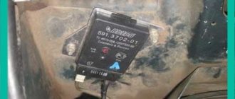
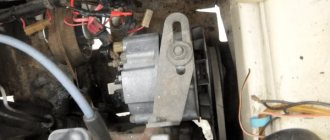
The Gazelle generator is a synchronous three-phase machine with electromagnetic excitation and is designed to convert rotational motion into electrical energy. The car is equipped with models 2502.3771 or 9422.3701, the power of which is about 1000 W. Do-it-yourself installation of the generator on the Gazelle is carried out using a mounting bracket on the right side of the power unit. It is driven by a V-belt from the crankshaft ratchet. It works in tandem with a built-in voltage regulator Y212A11E, which maintains the output voltage in the specified operating mode.
Service Features
Basic maintenance details:
- From time to time it is necessary to check the belt tension. If the belt is poorly tensioned, this will cause the unit to operate ineffectively. The voltage in the system will jump, and problems may appear in the operation of electrical equipment. If the strap is overtightened, this will lead to accelerated wear over time.
- Also, during maintenance, it is necessary to check the fastening of the unit, as well as the voltage regulator. If the unit is poorly secured, this will lead to vibrations affecting it, which, in turn, will also affect its service life.
- In addition, you periodically need to clean the unit body from dirt and check the condition of the brush assembly (to do this, it must be dismantled). The same applies to spring pressure and contact wheels. All detected problems must be corrected in a timely manner. If possible, you can also blow off the internal surfaces of the device with compressed air.
- If we are talking about preparing a unit for winter, then as part of maintenance it is necessary to remove the device and diagnose its technical condition as a whole. If necessary, the unit is disassembled and its mechanisms and windings are checked more thoroughly. All identified problems must be corrected. And before assembling the device, it is also recommended to blow it with compressed air, in particular, you need to pay attention to the rotor. It is better to replace the lubricant in bearing elements; to do this, the protective ring is dismantled, and the part itself is washed. As for the lubricant itself, it is filled to approximately 70% of the total volume, after which the device is assembled. There is no need to add lubricant to sealed bearings (the author of the video is the prosto gazelle channel).
Node diagnostics
Let's consider the diagnostic process using the example of the ZMZ-402 engine; the verification procedure should be carried out with an assistant:
- First you need to start the engine and wait until it warms up a little. Press on the gas so that the engine speed increases to 3 thousand per minute.
- Then turn on the electrical equipment, in particular, the optics (high beam), the stove, the wipers, and the light alarm.
- When the consumers are started, the voltage at the battery terminals is diagnosed. The voltage value in this case must be more than 12 volts, otherwise the control device, windings, brushes, and rings should be checked. The brushes could wear out over time and the slip rings could oxidize. To more thoroughly check the functionality of the regulator relay, you need to turn off all equipment and leave only the side lights. At engine speeds of about 1000-1200 per minute, the voltage value should be around 13.8-14.5 volts.
- If you want to check the excitation circuit of the unit, you must disconnect the connecting connector from the control device. Then the voltmeter probes with control are connected to the terminal Ш of the connector, as well as to the relay body.
- Next, the ignition is activated. If the light does not light, then perhaps the reason lies in poor contact of the winding with the slip rings or a break in the excitation winding. Also, such a malfunction may be caused by freezing brushes or inoperability of the slip rings of the rotor mechanism. The latter could oxidize, burn, or simply wear out (the author of the diagnostic video is Evgeniy Shevin).
Commercial vehicles GAZ
To quickly find the cause of a malfunction in your car, all Techs are equipped with modern and high-tech diagnostic equipment. More than 95% of all warranty repairs are performed on the same day.
Unified quality standards
To quickly find the cause of a malfunction in your car, all Techs are equipped with modern and high-tech diagnostic equipment. More than 95% of all warranty repairs are performed on the same day.
Qualified personnel
To quickly find the cause of a malfunction in your car, all Techs are equipped with modern and high-tech diagnostic equipment. More than 95% of all warranty repairs are performed on the same day.
Spare parts in stock and on order
To quickly find the cause of a malfunction in your car, all Techs are equipped with modern and high-tech diagnostic equipment. More than 95% of all warranty repairs are performed on the same day.
The traditionally low cost of standard hours (on average 30% less than competitors) and spare parts (3-5 times lower than analogues) allows you to minimize the cost of owning a GAZ car.
The total costs for scheduled maintenance of GAZ vehicles are on average 20% less than their European counterparts!
All services are certified by the Russian certification body. (Certification system for road transport)
Our service centers are modern and professional service stations. All of them undergo mandatory certification in accordance with GAZ corporate standards. Map of GAZ service stations Stores "GAZ car parts"
Increased warranty for main components and assemblies. The warranty period is extended for the duration of the GAZ vehicle undergoing warranty repairs.
Has a wider coverage of components included in the vehicle (competitors have more restrictions)
For limited parts, the warranty period is comparable to foreign analogues, and in some cases even longer.
Maintaining a full warranty when installing LPG.
Reimbursement of expenses to the consumer associated with the delivery of a faulty GAZ vehicle to service, incl. evacuation if the malfunction is of a production nature and is subject to repair under warranty;
Providing the owner of a GAZ vehicle with a guarantee for modifications or newly installed additional equipment and accessories (seller).
Possible malfunctions and ways to eliminate them
What are the signs that indicate that the generator set is not working properly?
- charging on the device disappears;
- lack of charge, equipment cannot be supplied with normal current;
- the on-board network generates too high a voltage of more than 14.7 volts;
- the unit itself began to work too noisily.
Brush replacement procedure
In accordance with the connection diagram, the procedure for replacing brushes is as follows:
- First, the battery terminals are disconnected.
- Next, you need to disconnect the connector from the brush holder.
- Using a flat-head screwdriver, you need to unscrew the two bolts securing the holder mount.
- Then the holder itself can be dismantled and the protrusion of the brushes from it can be checked. If the protrusion is less than 8 mm, then the holder itself or the brushes must be replaced. The installation procedure is carried out in reverse order. You also need to make sure that the brushes move smoothly around the holder.
Photo gallery “Changing brushes”
The nuances of replacing the belt
As for replacing the belt, this procedure is also not particularly complicated; it is performed as follows:
- First you will need a 12mm wrench to loosen the screw that secures the tension roller. Difficulties may arise due to the radiator located nearby. If the radiator bothers you, you can remove it.
- Next, you need to loosen the tension of the strap; to do this, using a 10mm wrench, you need to turn the tension roller screw counterclockwise.
- After completing these steps, the belt itself can be removed from the pulley.
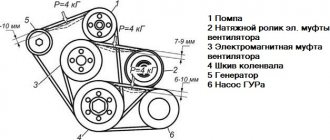
- Then a new strap is installed. Using a wrench, you need to rotate the roller screw until the deflection of the strap is 15 mm under a load of 8 kgf. In this case, the load itself must be applied to the center of the drive branch, that is, between the pulleys of the generator device and the pump. If the tension suits you, then you need to tighten the screw that secures the roller.
How to change bearings yourself?
To change bearing elements, you need to perform the following steps:
- First, the generator set itself is removed from the vehicle.
- Next, you need to remove the plastic cover from the unit body.
- After this, the brush holder from the regulator relay is unscrewed; before this, you need to disconnect the connector with wires from it.
- Then you will need to remove the four tie rods of the unit housing, as well as the cover along with the stator mechanism.
- Next, the winding terminals from the diode bridge are disconnected, the stator is dismantled, and, if necessary, the bridge itself.
- Now you can remove the drive pulley from the shaft, as well as the cover with the bearing device. The bearing itself is pressed in, so it can be removed using a special puller. The bearing is installed by pressing it in; assembly is carried out in the reverse order.
What battery should I use?
If you plan to install a 115-amp generator, you must have a 75 Ah battery. The optimal solution would be to purchase a 120-amp device and an 80 Ah battery. But if the number of electrical appliances in the cabin is off the charts, you can install 150. The battery must be designed for 90 ampere-hours.
Will the battery heat up if its capacity is greater than what the standard generator can produce? Absolutely not. The only problem will be that the factory generator will need more power. As a result, the winding may heat up and damage the varnish insulation. It is worth remembering that as the current load increases, the load on the belt increases, and, accordingly, on the rotor shaft, tension roller and pump.
Video “Diagnostics and repair of a generator device”
How to check and repair the unit yourself - the video below provides detailed instructions indicating the main points of this process (the author of the video is Channel 13).
It is impossible to operate a car without a generator, since it is responsible for the on-board power supply and electricity generation. GAZelle generator repair is one of the most common restoration work for these cars. The malfunction of this unit is easily determined by disruption of the vehicle and constant discharge of the battery. This is the main reason for the need to contact the service. It is difficult to repair a generator on your own, but it is quite possible if you wish.
What should you do first?
How to replace a diode bridge? This assumption should not be the first one when there is a problem with battery charging. Before you start disassembling the generator and changing the bridge, you need to check the charger brushes and the voltage regulating element. If everything is in order, then almost 100% of the diode bridge needs to be replaced.
The replacement process is not complicated, so this work can be easily done on your own. To check the functionality of the bridge, it must be removed from the generator. Of course, you can check without removing it, but it is very difficult and inconvenient.
Possible malfunctions and their causes
The main problems of the generator are:
- bearing failure;
- diode bridge problems;
- break in charging wires;
- short circuit in the stator;
- voltage regulator malfunction;
- “aging” of brushes or slip rings.
Like other transport mechanisms, the GAZelle generator is doomed to receive not only mechanical damage, but also electrical damage. Based on this, troubleshooting methods differ. Mechanical damage is considered to be damage to the springs, also to the swing bearings, drive belt or pulley and housing. Electrical problems include regulator failure, starter winding breakage, insulation melting, turn-to-turn short circuit, and brush wear.
The causes of malfunctions can be moisture and, accordingly, corrosion. Mechanical problems arise from “fatigue” of the material, non-compliance or violation of operating standards, from pollution, salts, and elevated temperatures.
Description
A generator is an electrical machine whose main task is to convert mechanical energy into electrical current. In a car, this cell is used not only to charge the battery, but also to power other electrical equipment (for example, the ECU and ignition system) while the engine is running. The Gazelle uses an alternating current generator. It is located in front of the engine, on the left side next to the main radiator.
As for the characteristics, the Gazelle generator produces a maximum voltage of 14 volts. Peak current can range from 65 to 120 amps depending on the model. But from the factory a generator with a capacity of no more than 80 amperes is installed on the Gazelle. And if we consider the first changes (95-2002), then it’s also 60.
Removing the GAZelle generator
To carry out repair operations, you should know how to properly remove the generator on a GAZelle without breaking anything. First of all, you will need to de-energize the vehicle networks. To do this, remove the negative terminal from the battery. Then the belt is loosened using a special mechanism and then removed. Only after this the bolts are unscrewed and the generator on the GAZelle can be removed.
Now you need to disassemble the part to determine the problem. To do this, remove the protective cover from the housing and unscrew the brush block. Having disconnected the wiring, de-energize the voltage regulator, after which it is also removed. The housing cover is removed simultaneously with the starter. Then the terminals are disconnected from the diode bridge, and if necessary, the bridge itself is removed. To check the generator on a GAZelle, you can use a test light or a specialized measuring device.
How to disassemble?
This procedure is quite simple. This operation requires a minimum of tools and an hour of free time. The procedure is carried out in several stages. On the right you need to turn off the ignition and remove the terminals from the battery.
It is also necessary to remove the wires from the generator itself. Next, use a wrench to loosen the tensioner pulley. Then unscrew the two screws that secure the device to the brackets.
Trouble-shooting
The main problem of this unit is the lack of voltage or its insufficiency. This is indicated by a suddenly dead battery or a corresponding light on the panel. A terminal removed from the battery while the engine is running can confirm or refute the guesses. If the engine stalls or the car stalls completely, the generator is faulty. Let's try to understand each of the main causes of this problem.
Broken or loose drive belt
In this situation, you will need to change the generator belt or its tension, which can be easily done by loosening the fastening nut, and tightening the belt after tightening it. Tension adjustment is performed by tilting the assembly itself away from the motor in a different direction. Having fixed the unit in the desired position, tighten the nut. To make it easier to rotate the unit, you will need to loosen the axial fastening nut. If it breaks, you will need to replace the GAZelle generator belt, for which you loosen the fastening nuts, tilt the assembly slightly and put on a new belt.
Replacing the tension pulley and accessory drive belt tensioning mechanism
We loosen the tension of the drive belt.
Completely unscrew the tension pulley bolt.
Remove the pulley from the tensioner axle.
If necessary, use a socket wrench or a 12mm socket to unscrew the three bolts securing the tensioner
Remove the tensioner mount from the engine
We install the tensioner and pulley on the engine in the reverse order, and then tighten the belt.
Many owners of ZMZ 406 power units were faced with the need to repair or replace the generator. Not everyone is able to do this procedure with their own hands. Let's look at the main subtleties and nuances of operation, repair and maintenance of the unit.
Possible faults
If the Gazelle generator malfunctions, the operation of all electronic devices is disrupted, and the battery is not recharged. A special indicator on the dashboard informs the driver about the breakdown of this part. With such a malfunction, starting the engine and driving the car is still possible, but until the battery is completely discharged. It is impossible to travel normally in such a car.
The main malfunctions of the generator include the following: violation of the integrity of the charging circuit wires, failure of bearings, damage to the diode bridge, short circuit of the stator winding, breakdown of the voltage regulator, wear of slip rings, excessive wear of brushes.
The Gazelle generator, like any car mechanism, can have both mechanical and electrical damage. Therefore, both the method of repairing the breakdown and the types of operations are different.
Mechanical damage includes wear and damage to rolling bearings, springs, damage to the integrity of the housing, pulley and drive belt.
Faults that are called electrical include breakage of the stator winding, cracks and wear of brushes, breakdown of the relay regulator, melting of the insulating coating of the turns, and interturn short circuits.
In case of any of these types of breakdowns, the car's generator does not fully perform its functions or completely fails, which affects the operation of all electronic devices and the engine as a whole.
Alternator belt, belt drive device
The alternator belt is a small part of the car that helps ensure its normal operation. Thanks to the generator belt, it is possible to transmit rotation from the crankshaft to the generator itself, which allows it to produce a sufficient amount of electrical energy to operate all kinds of equipment and systems.
The alternator belt is a simple rubber product and is one of a large number of car consumables that must be replaced on time according to the requirements of car manufacturers. The belt is an elastic rubber band; if it fails, the car will not be able to move independently. In order to avoid getting into an uncomfortable situation, you need to have an understanding of the structure of the car, the alternator belt itself, its location and replacement methods.
Simplicity of design and reliability have made it possible to use rubber alternator belts in all modern cars. This method of transmitting the rotational motion of shafts from one to another is the most trouble-free. However, despite this, it is necessary to carry out periodic visual inspections of the condition of the rubber belt, since it has a limited service life and may fail from time to time.
Today, there are many distinctive belt designs due to their use in different types of engines. Thus, all models of car alternator belts may differ in length, thickness, width and profile. Considering the fact that this rubber device is under constant heavy load, it must be strong enough and at the same time elastic to ensure a reliable connection between the generator pulleys and the crankshaft.
An important point that has a direct impact on the quality and durability of the belt is its temperature resistance. Since it is in constant motion under high voltage, it is subject to significant loads and temperatures. To ensure that the rubber material is not subject to rapid stretching and wear under the influence of those same constant loads, it must be sufficiently reliable and resistant to all influences.
The generator belt is made of special rubber, which has a strong multi-layer base inside of a special material and very reliable polymer threads. And for more reliable contact, different types of belts have different designs inside, allowing to increase the contact area and, accordingly, the reliability of the device. For greater reliability of the alternator belt and for it to have a number of other positive qualities, manufacturers pay sufficient attention to the development of new manufacturing technologies.
Removal process
Before replacing the generator on a Gazelle, it is important to remove the negative terminal of the battery, thereby de-energizing the vehicle’s network, and also disconnect the electrical wires from the part. Next, you need to loosen the belt tension using a special mechanism and remove it. Then, having unscrewed the two mounting bolts of the generator from the engine crankcase, we remove the generator itself from the engine compartment.
If the brushes fail, replacing them will not be difficult.
You just need to unscrew the two screws securing the brushes and remove them from the body. But in case of more serious malfunctions, the element must be disassembled and a detailed analysis of the faults.
About power
Owner reviews highlight the main drawback of any gazelle generator. This is not enough power. The amount of equipment used in the cabin is constantly growing, and GAZ still uses generators with the characteristics of the 90s. Wanting to ensure faster and easier engine starting in cold weather, many owners decide to install a battery with higher performance.
For example, instead of a 55 amp battery, they install a 80 amp battery. What is the end result? The situation depends on the condition of the electrical wiring. If the car is new, contact losses will be minimal and charging will be completed. But if it's an older car, there may be significant voltage drops under load. The result is the opposite effect.
Disassembly
This section describes a step-by-step process that will help you correctly disassemble the Gazelle generator.
So, first you need to remove the plastic protective cover from the case. Then unscrew the brush block and the voltage regulator, having first disconnected the wiring from it. Next, you should unscrew the four tie rods of the generator housing and remove the housing cover together with the stator. Then, having disconnected the winding terminals from the diode bridge, you need to remove the stator, and, if necessary, the diode bridge itself.
Next, remove the drive pulley and the cover with the rotor bearing from the shaft.
You can carry out the process of diagnosing generator parts using measuring instruments: E236 or a special test light.
Checking the condition of parts
Regardless of which generator is installed on the Gazelle, the causes of the malfunction, as a rule, can be of the same nature.
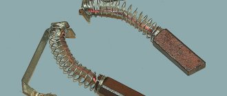
The generator brushes should not have chips or cracks; when pressed with a finger, they should freely sink into the channels of the brush holder, and return to their original position under the influence of the spring.
The length of the brushes should not be less than 4 mm, and if there is severe wear, they are replaced with new ones.
The stator is checked for short circuits between the turn windings and the housing.
This is done by connecting one terminal of the control light to the housing, and the second is alternately connected to one of the three terminals of the turns. In this case, if there is a short circuit to the housing, the indicator light will light up. Having discovered this type of malfunction, it is eliminated or the stator is completely replaced.
To check the stator for a short circuit between the turns, a test lamp is alternately connected to the two terminals of the windings. Moreover, if the light bulb lights up, then there is no break in the turns.
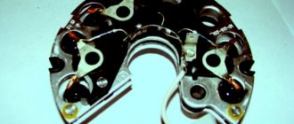
The generator rectifier unit should be cleaned of dust and dirt deposits. Next, you should check the diodes using a test lamp. Due to the fact that diodes of different polarities are placed in each section, they are checked with different battery connection polarities. If a faulty diode is detected, the rectifier unit is replaced.
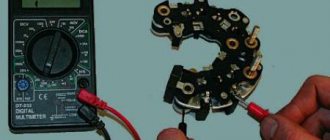
How to check a generator diode bridge
Test the unit on an installed or removed generator. To carry out the procedure, you will need wires and an ohmmeter, but an ordinary car light bulb will do.
Checking the diode bridge on a car
Before testing, remove the negative terminal from the battery and disconnect the wires from the generator. If you are using a multimeter, set it to ohmmeter mode. Touch the positive red probe to terminal “30” of the generator, and the negative probe to the metal body of the generator. If the rectifier unit is working properly, the device readings will show an infinitely high resistance. Otherwise, the diode bridge must be replaced.
The above test allows you to determine the integrity of the bridge in terms of the absence of a short circuit. At the next stage, the element is checked for breakdown. Using the red positive probe, touch terminal “30” of the generator again, and the negative probe, in turn, touch the axle mounting bolts (usually they are square). The resistance must be infinitely large. Now swap the probes: the readings should be 500-700 Ohms. You need to check each diode separately, changing the polarity of the tester!
Checking the generator after repair
After a detailed inspection and replacement of defective elements, the generator is assembled. Assembly occurs in reverse order. After the Gazelle generator is assembled, it is important to carry out diagnostics. The serviceable condition and correctness of its assembly can be determined by checking the rotation speed, during which the generator delivers a current of 40 A and 70 A. Diagnostics are carried out on a special stand. The electric motor of the testing stand smoothly changes the rotor speed. At the same time, the generator’s performance is measured, and the degree of its serviceability is determined.
Generator GAZ 2705
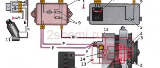
| Rice. 9.58. Generator: 1 — generator casing; 2 - voltage regulator with brushes; 3 - bolt + leads; 4 - capacitor; 5 — back cover of the generator; 6 — bearing sleeve; 7 — slip rings; 8 — thrust bushing; 9 — rotor winding; 10 — rotor poles; 11 — fan; 12 — generator shaft; 13 — front cover of the generator with bearing; 14 - bushing; 15 - pulley; 16 — washer; 17 — front bearing bushing; 18 — stator winding; 19 — rear bearing; 20 - stator; 21 — rectifier block diode; 22 — rectifier block; 23 - latches |
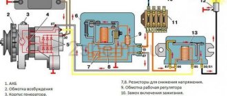
Generator 9422.3701 is a three-phase synchronous electric machine with electromagnetic excitation with a built-in rectifier unit and voltage regulator. The generator structure is shown in
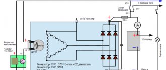
| Rice. 9.59. Electrical circuit of the generator: 1 - generator; 2 - voltage regulator; 3 - brush; 4 — contact ring; 5 - excitation winding; 6 — stator windings; 7 - capacitor; 8 — excitation winding diodes; 9 - power diodes |
The internal parts and windings of the generator are cooled by air, which is blown through windows in the rear and front covers using two centrifugal fans 11 mounted on the rotor shaft.
| Rice. 9.60. Diagram of a warning lamp with a battery: 1 - battery; 2 - control lamp with a power of 1-5 W; 3 - pin |
The generator parts should be checked using a test lamp (see.
| Rice. 9.61. Scheme for checking the serviceability of the voltage regulator: 1 - test lamp with a power of 21-35 W, 2 - battery, 3 - voltage regulator, 4 - brushes |
Build the circuit shown in
| Rice. 9.62. Scheme for checking the value of the regulated voltage: 1 - test lamp with a power of 21-35 W; 2-adjustable DC power supply; 3 - control voltmeter; 4 - voltage regulator; 5 - brushes |
To check the regulated voltage, you need to assemble the circuit shown in
| Rice. 9.63. Checking for absence of short circuit of the stator coils to the housing |
| Rice. 9.64. Checking the stator windings for open circuit |
On the stator, check that its windings are not shorted to the housing. To do this, you need one tip from the control lamp (see.
| Rice. 9.65. Checking the resistance of the rotor field winding |
| Rice. 9.66. Checking the rotor for absence of short circuit of the excitation winding to the housing |
The generator rotor must be checked for the absence of turn shorts using an ohmmeter (see.
| Rice. 9.67. Electrical circuit of the rectifier unit: 1 - power diode (positive polarity); 2 — mounting plate (negative); 3 — mounting plate (positive); 4 — output of excitation winding diodes; 5 - excitation winding diode; 6 - power diode of negative polarity |
| Rice. 9.68. Electrical circuit for checking diodes: 1 - diode; 2 - control lamp; 3-21 W; 3 - 12 V battery |
Rectifier block (
| Rice. 9.69. Electrical circuit for checking the generator on the stand: 1 - tachometer; 2 - generator; 3 - ammeter 100 A; 4 and 7 - switches; 5 - rheostat 70 A; 6 - battery; 8 - 30 V voltmeter; 9 — control lamp with a power of 3-4 W; 10 - drive motor |
The generator is assembled in the reverse order of disassembly. After assembly, the generator must be checked.
The serviceability of the generator and the correctness of its assembly are determined by checking the rotor speed, at which the generator begins to deliver a current of 40 A and 70 A. The test is carried out on a test bench consisting of an electric motor that smoothly changes the generator rotor speed up to 5000 min-1, a voltmeter, ammeter, rheostat, creating a load of up to 70 A in the generator and battery circuit (see Fig. 9.69).
To check the serviceability of the generator, it is necessary to turn on switch 7, and the control lamp 9 should light up. Bring the generator speed to 1500 min-1, voltmeter 8 should show a voltage of 13V. Indicator lamp 9 should go out. Increase the generator speed to 1800 min-1 and turn on switch 4. Using rheostat 5, set the load to 40 A using ammeter 3. Increase the generator speed to 5000 min-1 and set the load to 70 A using rheostat 5. Voltmeter 8 should show voltage 13, 5-14.2 V.
A working generator with a voltage regulator must meet the above parameters. This test can be carried out on stand E242.
Video about “Generator” for GAZ 2705
Replacing the voltage regulator on Sobol. Gas, VAZ, Without removing the generator. The light is on.
GAZelle generator repair. Low charge voltage.
GAZelle generator repair
Installing a dynamo on the engine
Installation on the engine is carried out in compliance with a certain technological process.
First, unscrew the fastening nuts of the generator brackets to the crankcase. Next, install the dynamo and secure the front mounting bolt. Then we move the front bracket and achieve alignment of the crankshaft ratchet with the drive flywheel of the part and the pump drive. By moving the bracket, we achieve elimination of the gap between the generator loop. Install the rear mounting bolt and firmly tighten the mounting nuts of the brackets to the engine crankcase. Next, we put the drive belt on the pulleys and tighten it using a tension bracket. We carry out a control check of the tightness of all threaded connections. We connect the part to the car's electrical network and put the terminals on the battery.
Therefore, solving such an issue is not particularly difficult, and besides, the process itself takes a small amount of time. You can save a lot on auto mechanic services.
Checking the generator on a car
After installing the part in place, you need to start the car engine. Next, you need to turn on the maximum number of electrical appliances available in your vehicle (interior heater fan, wipers, car radio, interior lighting) and turn on the headlights. In this case, even at idle engine speed, the voltage in the on-board network should be 13.8 V. With this indicator, operating the car will not cause any problems.
So, we found out how to change the generator on a Gazelle.