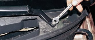
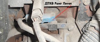
What is mass in a car?
“Ground” is the wire that connects the negative terminal of an electrical element (for example, an electromagnet) to the body of the product in which it is installed. ... The “ground” can be not only the wire, but also the body of the electrical element itself.
Interesting materials:
How to make a round hole in wood? How to make a socket box in a tree? How to mark eyebrows? How does the 1st action of a thunderstorm end? What happens if you reset your iPhone? What happens if you don’t register at the military registration and enlistment office? What happens if you take a screenshot on Instagram? What happens if you give an injection into the sciatic nerve? What happens if you do Wipe data? What happens if the angle of incidence is set to 0?
The brake lights on the VAZ 2111 do not light up: reasons
› Cars › VAZ › 2111 ›
The brake light indication is one of the most important signals indicating driver actions. Therefore, it is impossible to postpone repairs if the brake lights are not on.
If you notice a malfunction along the way and you are unable to eliminate the cause of the breakdown, turn on the hazard lights and drive at low speed to the nearest service station or a place suitable for DIY repairs.
SEARCH PRINCIPLE
To find a fault in any vehicle on-board network system, you should use the method of sequential elimination of elements.
The point is to consistently check electrical appliances and sections of the circuit, excluding elements from the list of reasons that could cause a breakdown. To do this, you need to clearly understand the design and operating principle of the system.
When troubleshooting, you need to move from the components that require the least effort to check, to the most difficult to diagnose elements.
Electrical diagram
We immediately emphasize that the pinout of connectors and color markings of wires may differ not only between different models of the same automaker, but also among one model of different years of manufacture. Before you start searching for the cause of the breakdown, you need to find an electrical diagram specifically for your car model.
We will consider the principle of operation of brake lights and the troubleshooting algorithm using the example of the VAZ 2101-2102 circuit. The photo shows the general diagram of the vehicle's lighting and light signaling. We need to isolate the components involved in the operation of brake lights.
- 6 – mounting fuse block;
- 13 – brake light switch. It is a non-locking button (returns to its original position after removing the force). Located directly next to the brake pedal. When the brake pedal is released, the contacts of the limit switch are open, no current passes through it. Accordingly, when pressed, the contacts close, allowing flow through the lamps;
- 19 – lamps that light up when you press the brake pedal.
We do not have a diagram of the mounting block, but we know in advance that the brake lights only work when the ignition is on.
There is a wire from the mounting block to the brake light limit switch, on which there is a constant + after the ignition is turned on. As soon as the limit switch contacts close, + goes to the brake light bulbs, which are connected in parallel.
The “ground” of the rear lights is common and is a wire screwed to the car body.
In the diagram we presented, the elements are depicted as close as possible to how they look in reality. Don’t be alarmed if you only find a schematic diagram for your car with symbolic images of the elements. Schematic diagram of external lighting for VAZ 2114, 2115:
- 3 – mounting block;
- 8 – lamps for side lights and brake lights;
- 11 – brake light limit switch;
- K4 – relay for monitoring the serviceability of brake light lamps and side lights.
LOCALIZING THE FAULT
Understanding the operating principle allows you to determine exactly why the brake lights may not light up:
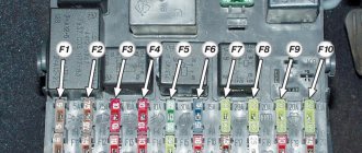
- The fuse has blown. In the diagram, the fuses are marked with the letter F (from English - Fuse) and the serial number of the seat in the fuse block, for example, F3;
- poor contact at connectors;
- the light bulbs have burned out, but since the lights are connected in parallel, the likelihood that 2 lamps will burn out at once is extremely low;
- poor contact on the negative terminal of the lights. In this case, problems may begin not only with the feet, but also with the lighting of the remaining lamps in the lanterns;
- Damage to the negative track in the lamp board. From the total mass directly to the brake light lamp, the minus goes along a special path on the board. The path may collapse from water or mechanical impact;
- malfunction of the brake light switch, the so-called frog;
- broken wiring, oxidation of contacts.
FAULT FINDING ALGORITHM
To detect a fault in the electrical network, you will need a multimeter or a tester, which you can make yourself. Previously, we told you how to use a multimeter, so we won’t focus on that.
The sequence of searching for the cause of the breakdown:
- Check the fuse for the brake light circuit. The location diagram of the fuse links can be found in the repair and operating manual for your car;
- often the symbol of the protected circuits is located on the back of the cover covering the fuse mounting block. If the installed fuse of the required rating immediately blows, there is a short circuit (short circuit) in the circuit. Please note that the fuse can protect not only the feet, but also other circuits. Installing a fuse with an increased rating is fraught with the risk of a car fire;
- If oxidation is detected on the terminals, clean the contacts mechanically or use an aerosol contact cleaner.
- Having turned on the ignition first and holding the brake pedal depressed, check whether there is power on the positive wire that goes from the limit switch to the rear light connector. If there is power, there is a malfunction in the lights themselves;
- check whether the positive signal is coming from the mounting block to the limit switch. If + comes, but when you press the brake pedal it does not appear on the second terminal of the limit switch, then the problem is in the “frog”;
- If there is no + at the limit switch terminal, examine the circuit up to the mounting block. If the wire is intact and securely fastened in the connectors, then the problem is in the mounting block.
If, for example, there is a + on both terminals of the limit switch when you press the brake pedal, but it does not come to the headlamp connector, then you need to look for the location of the wiring break. You can check the existing “frog” with a multimeter.
Simulate the state of the brake pedal being pressed, attach probes to the terminals, turning the multimeter into resistance measurement mode. If there is no resistance between the terminals, the limit switch is faulty.
If you removed the brake pedal limit switch for diagnostics, adjust its position correctly during installation. The brake lights should light up at the slightest touch of the brake pedal.
The search principle we considered is suitable for most cars. But, for example, in some cars, a relay is also involved in the operation of the brake lights, due to which the brake lights may also not light up. That is why it is always necessary to start by reading the electrical diagram.
Didn't find the information you are looking for? on our forum.
, please select a piece of text and press Ctrl+Enter.
The brake lights on the VAZ 2111 do not light up reasons Link to the main publication
Main causes of malfunction
The fuel pump can stop functioning only for two main reasons - lack of fuel in the beam or the occurrence of malfunctions. In the second case, the causes of breakdowns are usually as follows:
- Using poor fuel that does not meet quality standards.
- Valve failure. Most often, they simply become clogged, in which case it will be enough to dismantle the lid and mesh of the device and then clean them. If the valves are loose and their position is unreliable, the pump will need to be completely replaced.
- A blockage in the filtration system through which the fuel passes, causing excessive pressure to be applied to the pump, preventing it from functioning properly.
- Lack of timely refueling and driving a car with a minimum amount of fuel in the tank. This causes the device to idle, which quickly leads to its malfunction.
- Relay or fuse failure.
Where is the fuel pump relay located?
Where is the fuel pump relay located? The installation location of the relay varies depending on the make of the car. Most often, it is located under the hood, in the fuse and relay box.
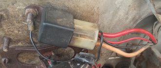
The fuel pump relay is designed in the circuit to prevent accidental application of high voltage to the fuel pump winding. The relay is standard and consists of a plastic body and coils with contacts. It is located in the car interior near the console. To access it, you need to remove the protection cover.
In appearance, it is a small box that resembles a “plug” with an American type of output. Each terminal has a marking that indicates the following: 31 – mass; 30– +12V constant (regardless of ignition); 15– +12 with the ignition on; 50– +12 when the starter is running; TD – signal from the ignition system; TF – engine temperature signal from the injection control unit KE. Outputs: 87 – supplies power to the fuel pump; 87H – oxygen sensor heating; 87V – turns on the starting injector.
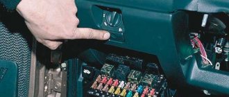
But sometimes the fuel pump does not turn on when the key is turned in the ignition. With what it can be connected? First of all, the fuse, although if it had blown, it would not work at all. Maybe the contact is bad?
If the electric fuel pump does not show any signs of life when the ignition is turned on, this does not mean that it has burned out. The cause of the malfunction may also be a relay. The easiest way to test your hearing is that when you turn on the ignition, the relay should click. If you don’t hear a click, there is a high probability that the “relay” is faulty.
It’s easy to check the functionality of the pump itself, so we do this:
- remove the protective casing, under which there is a block with relays and fuses;
- we unscrew the fastenings of the block, remove it, it remains attached to the wires;
- we pull the RB out of the block, place a jumper between two opposite contacts, thus directly supplying power to the BN;
- if with such a connection the electric motor of the pump begins to make noise, it means that the BN itself is working, most likely the fault is hidden in the relay;
- if there is no voltage on any of the contacts on the RB block, you should look for a break in the wiring; there may also be poor contact at the place where the wire is attached to the terminal.
Electrical diagram of a VAZ 2111 car
Installation, repair and replacement of front and rear dimensions of the VAZ 2110
Nearby there is a rear fog light, a tail light, a turn signal, a reflector, a brake signal and a marker. Fog lights will not only improve the exterior of the car, but will also help improve safety.
You can read about connecting fog lights here: There can be many reasons for malfunctions.
The most common problem is that the lamps burn out, which naturally makes it impossible to turn on the side lights.
Lamps brought to us from the Middle Kingdom are especially unreliable in this regard. Although they are attractive at a more than “democratic” price, and there are plenty of them at any retail outlet, you won’t be able to get away with them.
| This free collection contains all the necessary documentation for the electrical equipment of the VAZ-2111 car - the circuit itself, the heating system, headlight cleaner, electronic engine control module and fuse box. The VAZ 2111 is the first station wagon in the line of front-wheel drive cars, which is a modernized concept of the rear-wheel drive VAZ 2104. In it, the wiring diagram for the injector and a number of other components have undergone changes as part of the concept change. Diagrams for other models can be viewed here. Electrical diagram of VAZ-2111 carburetor1. block headlight; 2. front brake pad wear sensors; 3. fan motor activation sensor; 4. electric motor of the engine cooling system fan; 5. sound signal; 6. generator: 7. oil level sensor; 8. carburetor solenoid valve control unit; 9. heater controller; 10. recirculation valve switch; eleven. illumination lamp for heater control levers; 12. switch; 13. carburetor limit switch; 14. oil pressure warning lamp sensor; 15. spark plugs; 16. carburetor solenoid valve; 17. coolant temperature indicator sensor; 18. ignition distributor sensor; 19. ignition coil; 20. VAZ-2111 starter; 21. heater fan electric motor; 22. additional heater motor resistor; 23. speed sensor; 24. reverse light switch; 25. micromotor gearbox for heater damper drive; 26. recirculation valve; 27. brake fluid level sensor; 28. blocks for connecting the rear window washer motor; 29. battery; 30. windshield washer motor; 31.
rear window heating indicator lamp; 41. watch; 42. rear window heating switch; 43. steering column switch; 44. block for switching wires when installing headlights of a different type; 45. instrument lighting regulator; 46. ignition switch; 47. connectors for connecting the headlight cleaner wiring harness; 48. socket for a portable lamp; 49. individual interior lighting lamp; 50. brake light switch; 51. interior lamp; 52. on-board control system unit; 53. fuel level indicator sensor; 54. hazard warning switch VAZ-2111; 55. driver's seat belt sensor; 56. cigarette lighter; 57. ashtray illumination lamp; 58. glove compartment lamp switch; 59. block for connecting the on-board computer; 60. glove box lighting lamp; 61. side direction indicators; 62. switches in the front door pillars; 63. switches in the rear door pillars; 64. parking brake warning lamp switch; 65. trunk lighting; 66. temperature sensor for the heating system; 67. external rear lights; 68. internal rear lights; 69. license plate lights; 70. rear window heating element; 71. block for connecting an additional brake light for VAZ 2111. Wiring diagram for VAZ 2111 injector
Engine control system diagram for VAZ 2111 (MP7.0) - download VAZ 2111 engine control system diagram (M1.5.4) - download Engine control diagram for VAZ-2111 (1.5 8 cl) - download VAZ 2111 engine control circuit
Purpose of the plugs in block 26: 1 - to the low-voltage input of the tachometer in the instrument cluster; 3 - to the “Engine fault” lamp in the instrument cluster (from the controller); 4 - to the lamp switch located on the driver's door pillar; 5 - to the “Engine fault” lamp in the instrument cluster (supply “+” power); 6 — to the trip computer (fuel consumption signal); 7 - to the instrument cluster (vehicle speed signal 2111); 8 – to terminal “15” of the ignition switch (plug 4 of the switch block). VAZ-2111 fuse block diagram
CAR ELECTRONICS REPAIR |
How to improve the reversing light on a VAZ-2110
Many owners of "ten" cars complain about the lack of light when reversing. Meanwhile, moving “into the dark” is unsafe and inconvenient. What can be done?
On old cars, such as “classics”, the fight against darkness from behind is often solved “head-on” - by installing an additional headlight under the rear bumper. For the “ten”, this solution is partially suitable - a fog lamp hanging from the rear will definitely ruin the good appearance of this car. Meanwhile, you can attach additional lighting from behind, but in a slightly different way.
First, we will consider the easiest options, and then, at the end of the article, we will install an additional headlight on the rear bumper of the VAZ-2110.
Rear light intensity
If the “ten” does not have enough light when reversing and you want to improve the lighting, first you should make sure that the corresponding lights work as they should. There are more than enough reasons why they can shine dimly. This:
— Old light bulbs with blackened bulbs, working on the verge of burning out. It is necessary to check the condition of the lamps and, if necessary, replace them with new ones.
— Lamp lamps contaminated from the inside. They are not easy to wash. This will have to be done with a thin long stick with a rag wound through the hole in the light bulb.
— Poor-quality cloudy plastic of the lampshades (relevant for replaced non-factory lamps, for example, after an accident). In this case, you need to replace the lampshades with factory ones, which, as a rule, do not become cloudy.
— And, of course, the “trademark” sores of VAZs are the rear light trains. We will analyze this malfunction separately.
Voltage is supplied to the rear light bulbs on the VAZ-2110 not by wires, but through a cable. It is a flexible green tape with conductive tracks. In one place, a block with wires is connected to the cable and then the current flows along the paths to the lamps.
The problem is that the cables are extremely unreliable: they break, wear out, which is why the tracks are able to electrically communicate with each other.
All this leads to the taillights starting to work at random.
Surely everyone has seen how on a “ten”, when you press the brake, instead of a brake light, for example, the right turn signal and the left tail light turn on. This “miracle” happens precisely because of the trains.
The taillights are also connected to ground via a cable. Accordingly, if the “mass” track is not entirely serviceable, then the “mass” will also be bad. The lamps will glow dimly. This can also cause poor reverse lights on the VAZ-2110.
Advice:
If the lights shine normally, but there is still not enough light and you don’t want to bother with installing additional devices, then you can turn on the rear fog lights when driving backwards. This is at least a little, but it will add light.
Additional reversing lighting on the VAZ-2110
If everything is fine with the standard lights, then you can install an additional taillight on the “ten”.
This is somewhat more difficult to do than with the same “classic”, because you need to perform the installation beautifully. Based on the same beauty considerations, it is better if the headlight is narrow.
Then it won't be conspicuous. Instead of a fog lamp, you can use a powerful LED daytime running light.
A headlight suspended from the rear bumper on a 10 will look strange, so it needs to be installed directly into the bumper. It is plastic, so preparing the hole for the headlight will be quite simple.
It is necessary to accurately observe the dimensions so that the headlight fits tightly into the hole. You can attach it to the bumper with strong waterproof glue.
The bumper does not experience heavy torsional or bending loads, so fastening with glue will be quite reliable.
You need to connect the additional headlight from the wire that powers the standard taillights. Then the additional light will light up in parallel with the main one when reverse gear is engaged. The easiest place to connect to the wire is in the trunk. To do this, you need to peel back the floor carpet from the left wing and find the wiring harness.
The green wire is responsible for powering the rear lights. This can be checked if, with the ignition on and the engine not running, engage reverse gear and check for the presence of voltage on the indicated wire. Accordingly, when the reverse gear is turned off, there should be no voltage on it.
You can connect your wire to the standard one using the twisting method or “officially” using terminals. In any case, the connection point must be insulated with electrical tape. Next you need to run a new wire from the trunk under the bumper.
To do this you will have to drill a hole in the trunk floor. After completing the work, it is important to seal the hole with any sealant to prevent water from entering the trunk.
The “ground” wire from the additional headlight must be connected to the metal of the car body in any convenient place using a “bolt” terminal.
Now, when you engage reverse gear, your additional headlight will turn on along with the factory lights. As a rule, reverse gear is not engaged for long, so the headlight does not have time to heat up.
If you have concerns about the plastic of the bumper, then you should choose an LED daytime running light.
LEDs do not heat up very much during operation, so such a headlight will be absolutely safe for the bumper.
Loading…
The brake lights on the VAZ-2112 do not light up or work, why?
On all cars of the Tenth Family, the power lines for the lights contain many elements. There are lamp health relays, switches and fuses.
Therefore, if the brake lights on a VAZ-2112 do not light up, you need to check the entire chain. But the reason may look simple: sometimes the lamps do not turn on because the socket does not contact ground.
Circuits are easy to analyze, but finding the cause of a breakdown is difficult. Let's look into the details.
If one of the lamps does not light, it is simply replaced. See the example in the video - you need a P21 W
Standard version of the brake light operating diagram
Power is supplied to fuse F17 from the battery, then the current goes to limit switch contact 11, and then, if the limit switch is closed, a circuit is formed with the filament of lamps 7. But note: part of the circuit is relay K1, more precisely, its contacts 5 and 4.
A complete electrical diagram with explanations of the VAZ-2112 car is here.
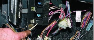
If the brake lights do not light up, on the VAZ-2112, as on all Tens, check one fuse. It is called F17 and is located in the mounting block to the left of the driver.
It is important to know: voltage is always present at one of the fuse terminals. Check it out!
A few words about the “serviceability relay”
The lamp health relay is called K1, and it is the largest in the mounting block. If you remove this relay, then when you press the pedal you can dial the voltage at terminal 5 (but not 4). Look at the diagram again, and it will become clear what we are talking about.
The largest relay in the block
All relay contacts are numbered. Check the voltage at the block terminals:
- 6 – “mass” potential;
- 2 – voltage “+12”, but only after turning on the ignition;
- 5 – “+12” by pressing the pedal;
- 4 – the terminal rings like a ground tap.
If the potential “0” is not generated at terminal “4,” it means that the lamp filaments are burnt out or there is a break in the wiring. Now consider something else: the ground potential has been detected, but the lamps do not light. This is where suspicions of a short circuit arise.
We turn on the brake lights forcibly
Relay K1 is successfully replaced with a pad with jumpers. In Fig. 1 just shows its diagram. If there is no such platform, you can temporarily close contacts 4-5. First, check everything mentioned above.
Have an observer watch what happens to the lamps. Press the pedal with one touch and release it. If the lamps do not turn on, check that the fuse is working properly. It's burned out, which means you're looking for a short circuit.
How to and how not to check the “0 Volt” potential
Let’s agree right away that we only work with a voltmeter. Voltage “+12” is caused by connecting one probe to ground. The presence of potential “zero” is checked differently: any of the probes is connected to a terminal with positive voltage, and then the second probe is connected to the wire being tested.
Consider the error: one probe is connected to ground, the second to the terminal being tested, and vol. Here they conclude that there is a “mass” potential, but this is wrong! If the contact with ground is broken, the device will also show “0”. That is, the number “0” does not contain information.
Wiring test for non-working brake lights (ground test)
Let's look at the basic diagram: the brake lights and the reversing lamps have a common ground pin. If contact with this pin is broken, the reverse lamps will not turn on. Well, brake lights too.
Connector for connecting “internal” lights
On the left side there is a connector through which the wiring goes to the fifth door. The connector has black and red wires. Check the voltages on them. Most often the ground on the black wire does not ring. But maybe the connector itself needs to be cleaned.
Usually, if the ground breaks, another pin is used - the one that is connected to the glass heating coil.
If the “plus” does not come to the red wire, we check the “frog”. It's simple here:
- Disconnect the connector with two wires from the limit switch;
- Using 17mm wrenches, loosen the two nuts: holding the lower nut, rotate the upper one;
- The end switch is removed as an assembly and checked with an ohmmeter.
By the way, one of the connector terminals receives a voltage of “12 Volts”. Check it!
If all the steps do not lead to results, there is only one thing left: contact a qualified electrician. We wish you success.
