A common failure associated with the fuel system is that the fuel pump fuse blows. In this case, power is not supplied to the pump, and the fuel pump itself stops pumping gasoline into the main line. As a result, the car stalls, the pump does not buzz in the gas tank after turning the ignition key, and the engine does not start.
We also recommend reading the article on how to check the fuel pump relay with your own hands. From this article you will learn about where the fuel pump relay is located, as well as the available methods for checking it yourself.
Checking the fuel pump fuse
Before starting the test, it is advisable to study the location of fuses in the blocks of various cars. This can be done using the operating instructions for a specific vehicle, on specialized auto forums, etc. Having decided which fuse is responsible for the fuel pump and where the specified element is located, you can begin to look for the problem.
- To check and replace the fuel pump fuse yourself, you will need a special clamp or tweezers. First you need to remove the cover from the fuse box, which is usually secured with latches. Next, we find the element itself responsible for the operation of the fuel pump. For example, in Priora the solution is designated F13 and passes a current of 15A.
- Now we remove the element using a clamp, pliers or tweezers. If the fuse is blown, then you should carry out an in-depth diagnosis of the wiring condition and check the contacts on the fuel pump itself, after which the faulty element in the pump circuit is replaced with a new one.
Please note that you should only replace blown fuses on your car after the underlying problem has been resolved. Simply replacing a fuse will cause the new element to quickly fail again.
If the fuel pump fuse is intact, then the pump relay and the fuel pump itself are checked. The terminals tend to oxidize over time, the pump relay sticks, electrical circuit breaks may occur, etc.
Note that on the VAZ 2110 and Priora the pump fuse is located next to the relay. It is enough to lightly knock on the relay itself, which often allows you to restore its functionality.
Why do fuel pump fuses blow?
A fuse is a small element whose task in the design of electrical circuits is to melt in the event of an overload. The device melts and the current-carrying circuit opens.
Using the example of a solution from the popular VAZ Priora model, we can superficially examine the design and operating principle of the fuse. The device is small, the outer casing is made of plexiglass.
There is a conductive element inside. Such an element is based on several plates, which are made of different materials. Between these plates there is a special low-melting material. Electricity passes through this material, which allows the fuse to be an integral part of the electrical power circuit of the fuel pump.
Fuses have a special marking in the form of the letter F. This designation indicates that the fuse element belongs to a circuit whose power is not large. To calculate the current that certain devices are designed for, you need to divide the power by 220. The result will be a figure in amperes.
If the fuse is blown, then such a malfunction is often caused by the following reasons:
- short circuit in the electrical circuit;
- failure of the fuel pump relay;
- low quality of the fuse itself;
In other words, more often the fuel pump fuse blows due to faults in the electrical circuits or as a result of failure of the components of the pump power circuit. Note that situations also arise when the fuel pump fuse burns on its own, but this phenomenon occurs much less frequently with high-quality elements.
About work culture and regulations
The fuel system of LADA Kalina (and not only) requires cleanliness of both the gasoline itself and the components involved in its supply to the engine. All dismantled parts of the system must be perfectly cleaned and washed before reinstallation. When replacing the mesh, we also recommend replacing the filter used for fine fuel purification. Where is this filter located? It is located inside the right stern wheel arch near the jack stand cup. According to the regulations, this element requires replacement no less than after 30 thousand kilometers.
Note that there are two more mesh filters along the fuel path in the circuit, one of which is installed in front of the fuel pressure regulator, and the second directly in front of the injectors. These filters “take over” fuel that has already been practically purified in the preliminary stages, so the need to replace them is extremely rare.
How are the blocks separated in the machine?
The main type of block is placed in the most convenient place for the driver. In this version of the VAZ it is located on the left side of the body directly at the steering wheel. Easy access to the unit is provided using a built-in button located next to the car's headlight control.
2 backup units with relays are located separately in the right and central parts of the console just behind the dashboard. One of the fuses shown below in the diagram will be located at a distance from the rest of the list - it can be found in a special compartment behind the main fuse block, next to the mounting block. To timely repair electrical equipment on a VAZ-2110, you need to learn how to quickly determine the location of a blown fuse, and also know which elements of the car its failure will affect.
As for the direct replacement of the latter, it is by monitoring the serviceability of the latter that it is necessary to begin diagnosing the failed element of the electrical circuit. The fuse is removed with tweezers or, if the thickness of the fingers allows, simply by hand from the landing block and inspected in the light to see if the fusible conductor is closed. In the event of combustion, a new fuse of the appropriate rating must be installed in place of the failed one in the fuse box.
Replacement video
In conclusion, I would like to note that the creators of the VAZ 2110 actually did not limit themselves to just this fuse box; in fact, there is another place, more hidden from prying eyes and the driver - under the decorative panel, to the left of the center console pillar at the passenger’s feet.
There are three fuses located here: the ignition module, the fuel pump and the sensor assembly (speed, oxygen, air flow and absorber purge). In addition, there are three relays: ignition relay, fuel pump relay, electric fan relay.
So, when looking for the cause of your car breakdown, do not forget about them. Read about the VAZ 2109 fuse box here.
FakeHeader
Comments 5
tell me what is the reason? same issue today, I looked through everything, the front light is on and that’s it
solved a problem? Today the same bullshit came up
no ((you need to remove the wiring and look for what the problem is... it disappears then lights up again ((
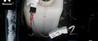
There are usually two reasons, either the pump is about to die, or the wiring is frayed in the area of the engine oil filler neck.
hmm... I found another diagram 1 - ignition module, controller; 2 – canister purge valve, vehicle speed sensor, oxygen (heating) sensor, air flow sensor; 3 – fuel pump relay, fuel pump, injectors. Additional relays: 4 – electric fan relay; 5 – electric fuel pump relay; 6 – main relay (ignition relay).
It turns out that the canister purge valve fuse is on, the vehicle speed sensor, the oxygen (heating) sensor, the air flow sensor... omg so what's the problem?
↑ VAZ-2110 fuse block diagram
The VAZ "Ten" has 2 types of mounting blocks. The main unit fuse box diagram contains a significant portion of fuses and switching relays. In the latest models, the number of relays has increased to 8. Schematically, the fuse box shows a set of twenty fuses arranged in 2 rows. Each component in the block has its own position, on which the value is engraved. The mounting location is provided with a graphic symbol indicating the powered electrical receiver.
The additional block has elements for protecting the power supply circuits of the engine. It contains 3 fuses and 3 relays, which are responsible for the ignition and proper operation of the electric motors of the fan and fuel pump. You can find it inside the center console. It is located behind a plastic cover attached with screws, to the left of the front passenger seat.
If a carburetor is installed on a VAZ 2110, then even if the fuse box is not working, the car is able to operate. Full operation of other components is not guaranteed. In injection models, a separate line is responsible for the uninterrupted operation of the injector, which ensures the timely flow of fuel into the system.
Where is the fuse and fuel pump relay on the VAZ 2110
It’s worth saying right away that the fuse and relay for the VAZ 2110 injector fuel pump are located in the same place. They are both located in the center console on the passenger side below. The main task of a relay in an electrical circuit is to close and open a circuit. Thanks to this, the circuit is protected from high inrush current.
| F1 - 5A | License plate lamps. Instrument lighting lamps. Side light indicator lamp. Trunk light. Left side marker lamps. |
| F2 - 7.5A | Left headlight (low beam). |
| F3 - 10A | Left headlight (high beam). |
| F4 - 10A | Right fog lamp. |
| F5 - 30A | Electric door window motors. |
| F6 - 15A | Portable lamp. |
| F7 - 20A | Engine cooling fan electric motor. Sound signal. |
| F8 - 20A | Rear window heating element. Relay (contacts) for turning on the heated rear window. |
| F9 - 20A | Recirculation valve. Windshield and headlight cleaners and washers. Relay (coil) for switching on the heated rear window. |
| F10 - 20A | Spare. |
| F11 - 5A | Starboard side marker lamps. |
| F12 - 7.5A | Right headlight (low beam). |
| F13 - 10A | Right headlight (high beam). Indicator lamp for turning on the high beam. |
| F14 - 10A | Left fog lamp. |
| F15 - 20A | Electrically heated seats. Locking the trunk lock. |
| F16 - 10A | Relay-breaker for direction indicators and hazard warning lights (in hazard warning mode). Hazard warning lamp. |
| F17 - 7.5A | Interior lighting lamp. Individual backlight lamp. Ignition switch illumination lamp. Brake light bulbs. Clock (or trip computer). |
| F18 - 25A | Glove box lighting lamp. Heater controller. Cigarette lighter. |
| F19 - 10A | Locking door locks. Relay for monitoring the health of brake light lamps and side lights. Direction indicators with warning lamps. Reversing lamps. Generator excitation winding. On-board control system display unit. Instrument cluster. Clock (or trip computer). |
| F20 - 7.5A | Rear fog lamps. |
| K1 | relay for monitoring the health of light bulbs; |
| K2 | front wiper relay; |
| K3 | repeater and alarm relay interrupter; |
| K4 | low beam relay; |
| K5 | high beam relay; |
| K6 | additional relay; |
| K7 | rear window heating relay; |
| K8 | backup relay |
A similar type of relay is installed on the fuel pump, protecting the circuit when the engine starts. It consists of a plastic housing that houses an electromagnetic coil with a core. The incoming voltage allows the core contacts to close. The operating current of the relay is 30 Amperes.
Where is the fuel pump relay located on a VAZ 2110?
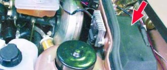
People often wonder where the fuel pump relay is located on a VAZ 2110; this photo will help you answer this question ↓
Where is the fuel pump relay located on a VAZ 2110?
Location of the relay and fuse for the fuel pump VAZ 2110 injector
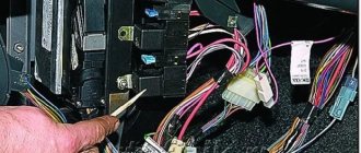
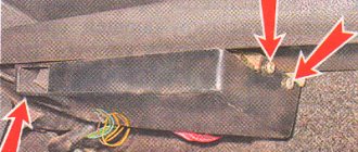
If during repairs or diagnostics, the fault indicates a relay and fuse, then they must be removed and replaced with new parts. You should prepare a Phillips screwdriver and position yourself on the passenger side. At the bottom of the center console there is a cover secured with two screws. You need to unscrew them. It is there that the panel is located where the VAZ 2110 injector fuel pump relay is located and where the fuse for the VAZ 2110 fuel pump is located.
Rice. 2 Removing the side cover
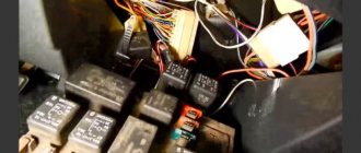
After removing the protective cover, access to the power fuses and relays of the car appears. The required parts responsible for the operation of the fuel pump are marked with numbers 5 and 2 in the center of the photograph.
Fig.3 Power fuses and relays
Why does the VAZ 2110 fuel pump fuse blow out?
Fuse failure is a fairly common occurrence. Burnout indicates one thing - there is a short circuit in the fuel pump power system. In this case, you can change the fuse, drive away for several days without problems, and the situation will repeat again. So it is necessary to look for the reason.
The most common culprits are:
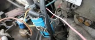
- the wiring harness above the exhaust manifold melted;
- wires under the carpet are damaged or melted;
- interturn short circuit in the pump motor;
- The positive wire going to the pump is damaged (current leakage to ground).
To identify the cause, you should disconnect the power supply from the fuel pump and turn on the ignition. If the fuse is blown, then the problem is in the wiring. Remained intact - short circuit in the electric motor. In the first case, you have to inspect the entire harness, looking for contact of the “plus” with the ground. As a rule, this is a gray wire running from the relay to the tank. The harness runs along the central tunnel, and not from the left threshold.
Description for Renault Kanga 2nd generation
Communication block
It is quite difficult to get to it. To do this, you need to remove the battery, unscrew the cover of the unit next to it and turn it over.
Scheme
Description
| 1 | 7.5A - Fuse for right side light bulbs (172-226) |
| 2 | 7.5A - Fuse for left side lights (173-227) - right rear light (172) - middle license plate lamp (1324) cigarette lighter (101) - socket for additional equipment of the 1st row of seats (506) - door lock and emergency switch alarm (1391) - headlight range control switch (562) - climate control panel (319-419) - audio system (261) - multifunction display |
| 3 | 10A - Right headlight fuse (low beam) (226) - headlight range control switch (562) - right headlight range control motor (538) |
| 4 | 10A - Left headlight fuse (low beam) (227) - left headlight leveling motor (537) |
| 5 | 20A - Fuse for right and left fog lights (176-177) |
| 6 | 10A - Left headlight fuse (high beam) (227) |
| 7 | 10A - Right headlight fuse (high beam) (226) |
| 8 | 25A - ECU of the anti-lock brake system (118) or trajectory stabilization system (1094) |
| 9 | 30A - Windshield wiper motor fuse (212) |
| 10 | 5A - Fuse “+” after the ignition switch of the electric power steering (1232) |
| 11 | Not used |
| 12 | 20A - automatic transmission ECU (119) |
| 13 | Not used |
| 14 | 15A Car with a gasoline engine: injectors 1-2-3-4 (193-194-195-196) – adsorber (371) – lower oxygen sensor (242) – upper oxygen sensor (887) or Car with a diesel engine: supply regulator fuel (1105) – cylinder sensor solenoid valve (746) |
| 15 | Not used |
| 16 | 5A - automatic transmission ECU (119) |
| 17 | 7.5A - Auxiliary heater relay 1 (1067) - Auxiliary heater relay 2 (1068) - Diagnostic connector (225) - Airbag/seat belt pretensioner ECU (756) - Parking assist ECU (1222) |
| 18 | 5A - Fuse "+" after the ignition switch, water in fuel sensor (414) - relay unit in the engine compartment 2 (1683) - injection computer (120) |
| 19 | 10A - Fuse “+” after the ignition switch of the reverse light switch (155) or the reverse light switch with top dead center sensor (1109) |
| 20 | 20A -Injection computer (120) |
| 21 | Not used |
| 22 | 10A - Fuse for the electromagnetic clutch of the air conditioning compressor (171) |
| 23 | 30A - Heated rear window (200) - outside rear view mirrors (239-240) |
Power supply circuit block
Scheme
Purpose
| 1 | 60A Coolant Heater Interface Unit |
| 2 | 7A Diesel engine glow plug relay unit (980) - coolant heater interface unit |
| 3 | 30A Relay block in the engine compartment 2 (1683) – heating element of the fuel heater |
| 4 | 40A Door Power Window Motor Fuse |
| 5 | 70A Fuse and relay box in the passenger compartment |
| 6 | 50A ABS ECU (1094) |
| 7 | 40A Additional heating relay 1 |
| 8 | 70A Fuse and relay box in the passenger compartment |
| 9 | 70A Additional heating relay 2 |
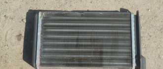
Mechanical fuel pump "tens" VAZ
The VAZ 2110 (Lada-110) car has been produced at AvtoVAZ since 1995, and the first engines on this model came with carburetors. Eight-valve VAZ 2110 engines with a power of 72 hp. With. were set to “tens” until 2000, and the fuel pumps on these internal combustion engines, accordingly, were mechanical.
The 2110 mechanical fuel pump consists of parts:
- metal case (two halves);
- top cover;
- pusher with diaphragm;
- two valves;
- return spring.
Gasoline is pumped from the fuel tank by oscillating the diaphragm and opening and closing valves. The diaphragm with a pusher is driven by the camshaft eccentric; on the lower BN housing there is a manual pumping lever for gasoline.
Which fuse is for the cigarette lighter?
Some car models have a problem when the cigarette lighter fuse fails. This is due to the fact that additional electrical equipment is connected to the cigarette lighter. We are talking about video recorders, air purification devices, FM modulators, navigators, chargers and other devices. The automotive market is full of gadgets that need to be plugged into the cigarette lighter socket, and new items continue to be added to auto stores.
Some of them are low-quality recorders, which often cause the device to break down. This is due to incorrect operation of the gadget and constant voltage surges in the electrical wiring. In this case, not only the fuse, but also the cigarette lighter may break.
DVR plug that requires connection to a cigarette lighter device
There is a possibility of it breaking if a device with a voltage converter is connected to the cigarette lighter. These could be laptops, media players, electric kettles. The device must be protected by a fuse that will take the “blow” in case of overvoltage of the wiring.
In cars, the component is protected by a fuse, but sometimes there is no fuse. This doesn't mean it doesn't exist. It’s just that the cigarette lighter may have the same circuit with a radio or other device, which means they have the same fuse.
Where is?
In most cars, the switch is located in the fuse box.
This is a special device that contains all the fuses that protect the electrical equipment of the vehicle.
This is what the diagram of an average installation power supply for transport looks like
If you don’t know where the checkpoint is, we’ll give you some tips on how to find it:
- Use the vehicle's operating manual. The instructions will indicate the location of the block. The PP will probably be in it. Note that modern vehicles are equipped with several units. One of them contains fuses, the other contains relays. Depends on the manufacturer. One of the blocks will be located in the passenger compartment, and the other in the engine compartment. The block in the cabin is located on the left side of the dashboard, near the steering wheel. It can be located behind the glove box of the car. As for the second unit, it may be located in the engine compartment near the battery. The device responsible for the cigarette lighter can be located not only in the fuse box, but also in the relay box. It is possible that the relay protects several wiring circuits, so it is likely that the relay is responsible for the lighting device. If you have problems finding a PP, use the service book for the car.
- Open the unit cover. On the reverse side of the plastic cover there is a diagram of the location of fusible parts. Each is responsible for the performance of a specific device. Study the diagram to understand where the PP is located. Perhaps the relay of the car radio or other device is responsible for the operation of the cigarette lighter. Therefore, the scheme needs to be studied in detail.
- Ask online. Today there are many thematic automobile forums on the Internet. Ask the owners of your car model where the PP is located and how to replace it. There may be some nuances that should be taken into account when replacing, so it won’t hurt to familiarize yourself with them.
This is what the power supply diagram looks like, from which you can determine the location of the power supply
Repair, replacement
If the external contacts have oxidized (on the assembly itself or in the seat), then they are cleaned, the break in the circuit is corrected by twisting, replacing the wiring, installing a new fuse - perhaps these are all cases when repairs are advisable.
If there is a problem inside the relay, then this usually cannot be repaired - they throw it away and buy a new one. Of course, you can try to open the device and figure out its insides - but the body of the part is sealed, you will need to re-glue it securely. Even if it is possible to repair the internal parts, then, as a rule, the lifespan of a circuit breaker that has survived such intervention may not be long.
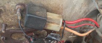
Although there are successful cases of repair - see fig. Below is a successful one, but we personally don’t inspire much confidence.
Let us describe the restoration of the Opel Vectra relay. In this case, such a repair is successful and appropriate - all that was required was to solder the legs (the photo shows that the solder has come off).
Installation and selection of relays is simple: take a device for a specific car brand or one with similar parameters, replacement - the old one is removed from its seat and the new one is inserted. We have described the placement locations and an example of how to remove the block from the relay on a VAZ.
You need to understand that we examined the problems of the relay. That is, even if it is working properly, it may be the fuel pump that is broken or its line may be broken. We touched upon some aspects of checking this node quite deeply. The user will be able to test two mechanisms.
DIY step-by-step repair
If you decide to figure out for yourself why the cigarette lighter is not working and repair the breakdown of your car, then below are the repair instructions.
For this you will need:
- gloves;
- new fuse;
- soldering iron;
- Screwdriver Set;
- tweezers.
Advice! It is not always necessary to go to a car service center. If you understand your car at least a little, then with the help of hints you will figure out why this or that part in the car does not work.
Procedure:
First of all, you need to turn off the power to the car to avoid a short circuit. To do this, remove the negative terminal from the battery; Often the cigarette lighter is located on the center console. Move the driver's seat to get closer to the inoperative device; Using a flashlight, you need to inspect the device socket for the presence of foreign objects. If there are any, then use tweezers to remove them from the socket; If the device does not work, then the first thing you need to do is check the fuse. Due to its burnout, current stops flowing to the device. The instruction book will help you in your search. If necessary, replace it and check again whether the device works; if the problem is not solved, then you should remove the cigarette lighter using pliers
Usually it sits tightly, so you need to make a little effort, but do everything carefully and not harshly, so as not to damage the rim and wires; Pay attention to the appearance of the device. There should be no dark soot on it
Check the wires for integrity; all connectors should be seated tightly; if you find a soldered wire, then solder them using a soldering iron and do not forget about good insulation; then assemble the device and test it for functionality.
VAZ 2115 fuses (Mounting block)
A fairly common type of breakdown in cars is the shutdown of the vehicle's electrical equipment. Quite often this is due to a blown fuse. To quickly fix such a problem, you need to know exactly where the fuse is located, which is responsible for the disabled electronic component of the car, as well as how to replace it.
Where are the fuses located?
No vehicle is designed to have fuses scattered in different places. In every car, including the VAZ 2115, all fuses are located in a special block called a fuse block.
Like most cars, the VAZ 2115 has two fuse blocks. One of them is located in the car's interior, under the dashboard, and the second in the engine compartment, near the left glass.
What fuses are located on the VAZ 2115
Let us recall that in the previous article we looked at malfunctions of the ignition module on the VAZ 2115, its repair and replacement with our own hands.
Each fuse, which is located in the vehicle fuse box, has its own marking, by which you can determine what it is responsible for:
1. “K1” – this element of the fuse block is responsible for the headlight cleaning system relay.2. “K2” - that element of the fuse block is responsible for the relay of the system for switching turning lights, as well as for the alarm system.3. “K3” – is responsible for the windshield cleaning system.4. “K4” – is responsible for monitoring the performance of the lamps.5. “K5” – is responsible for the electric window system.6. “K6” – is responsible for sound signals.7. “K7” – is responsible for the rear window heating system.8. “K8” – is responsible for illuminating the roadway in high beam mode.9. “K9” – is responsible for illuminating the roadway in low beam mode.10. "F1" - "F20" are special fuses.
The design of the fuse box on the VAZ 2115
The interior fuse box has a slightly different structure than the one located under the hood. It includes an electronic control unit, three fuses, and three relays.
Just like in the fuse box located in the engine compartment, here each fuse has its own purpose.
If we describe them from top to bottom, we get the following:
1. The fuse that controls the fuel pump. Its current strength is 15 amperes.2. The fuse is responsible for the electric radiator fan relay, the valve located on the adsorber purge, as well as for the mass air flow sensor, DC and DC. The amperage of this fuse is 7.5 amps. 3. Fuse that controls the ECU. The current on this fuse is 7.5 amps.
Also, in order to fully understand fuse blocks, you should know about the relays that are located in the interior fuse block.
Below you can find their description from top to bottom:
1. Relay, which is responsible for turning on the fuel pump.2. A relay that is responsible for turning on the electric radiator fan of the cooling system.3. Main relay.
How to identify a blown fuse and replace it?
As we said above, each fuse that is located in the car is responsible for its own electrical equipment. In this regard, you only need to look at the cover of the fuse box, and according to the diagram that is printed on it, determine the location of the required fuse.
To get to the fuses themselves, just press the latch with one hand and open the fuse box cover with the other.
How can I be sure the fuse is blown?
There are two main ways to evaluate the performance of a fuse. The first, simpler, but less reliable - “by eye”. To do this, pull out the fuse and see if its middle part is intact.
The second method of checking the fuse is better. You need to turn on the ignition and measure the voltage at the fuse contacts one by one. If one has it, but the other does not, then the fuse has blown.
In conclusion, I would like to note that if your fuses blow quite often, then you should check all the wiring of the vehicle. This requires serious experience and specific knowledge. If you do not have them, then it is better to contact an experienced specialist at a service station.
Operating principle of the fuel pump relay
The EBN relay itself is a regular EM circuit breaker, but there is also a somewhat complex design if the device controls additional car options. The product does not have sensors inside; it responds only to power, which generates an electromagnetic force that closes the contacts. The device is completely controlled by the vehicle's electronic control unit (ECU), which supplies it with power and commands.
The purpose of EM relays is to switch lines (control, control) of more powerful devices, as well as combine and decompose pulses. The process can be most accurately represented by the “trigger (close) - release (return to initial position)” diagram.
Consider the algorithm according to the figure above:
- The state at zero input is shown. the magnitude of X - current Iin in winding 7.
- When in. the current Iin begins to increase at a specific mark, the armature 10 falls off the stopper 77 and is magnetized to the rod 12.
- As the armature moves, its upper end, transmitting force through the pushing element 9, bends the contact spring 6 upward until its part 8 comes into contact with that 7 of the spring 5, which then extends upward until it stops 4.
- Result: in input. line after completion of the transition gap, current Iout begins to flow from out. Y value.
- With future growth of input. The output current changes are negligible, we can assume that they do not exist.
- When does it come in? the current decreases; at a specific value, the mechanical pressure of the bending springs overcomes the EM force, which attracts the armature to the rod 12.
- The contact elements open, and the output circuit is de-energized. With a subsequent current pulse, the cycle repeats.
The operation algorithm in the car is as follows. After turning the key and starting the ignition, the auto switch starts working, sends a command to the VT and it is activated for 2-3 seconds. To the required pressure on the ramp. Then the device deactivates the pump, and then it starts only when the engine is rotated by the starter or while driving. After stopping the engine, the device turns off the EBN and relieves pressure.
Meaning of contacts
There are different pinouts of the fuel pump auto switch, the most common are 4 and 5 pins, but there are also ones with 7 and 9 or another number of pins - they also control some other options of the car. Each terminal has a marking; it and the circuit are always indicated on the body of the device.
The most popular standard, 4 contacts:
- 30 - general (under voltage);
- 87 (maybe 87a or 88) - for power lines. On foreign circuits - 87a, on Russian ones - 88, the only difference is in the designation;
- 86, 85 - electromagnet winding, for commands from the ECU.
Model with 6 contacts, each signed:
Example of relay contacts with extended functionality:
Example of an EBN auto switch on a Mercedes E (there are 8 pins):
There are also options with unusual digital markings:
We will consider 4-pin types with the usual contact designations, since they are the most popular. There is a basic principle: the conclusions are connected to the lines corresponding to them - information about which of them corresponds to the relay contact is in the technical documentation of the car, the device itself. The diagram is easy to find on the Internet. That is, it will not be difficult to navigate through the different options.
An example of pinout with wire colors (standard colors, but may be different) from the ECU:
So, the conclusions of the 4-pin relay:
- 2 - for power cores;
- 2 - for ECU commands.
Pin 30 is always there; in the deactivated position it is closed to 87a, and when the internal combustion engine starts, it is closed to 87 (if the relay has separate such pins). But in four-contact releases, 2 terminals - 87a, 87 - are connected into one, the auto switch works like a regular EM circuit switch. If the power is removed from the starter, it keeps the contacts closed until the engine stops.
Scheme
Below is a diagram of the fuel pump relay in several versions, showing the terminal connections:
EBN relay functions
The main task is to control the fuel pump. When on ignition - creates pressure in the fuel pipe by activating the fuel pump (BN) for several seconds. After this, the latter will function either with starter cranking or with the internal combustion engine activated.
The working product will still partially activate the VT when the starter is operating, if its control resistor is working properly.
The release may be responsible for some other options, for example:
- heating oxygen sensor. It is triggered on the relay in different ways: on some - directly from the BN, on others - through its own transistor. Outdated auto switches do not have such a detector, but heating is done - operation occurs when the pump starts;
- activation of the starting injector (PF) during a “cold” start. This works as long as the starter does, depending on the t° of the motor. The release operates for a certain period, depending on t°: data about it comes from the KE (injection) control unit to the ECU, and it determines the time. So, at +60 on the engine, the PF starts for a fraction of a second, but at low values it can work for 8–10 seconds. The nozzle has 1, or less often 2, channels: for the flow of the sprayed liquid, or it plus a second one - for supplying a similar substance, steam, gas, which helps the specified process take place. A high-quality unit produces a cone-shaped spray—an even, continuous spray appears.
The latest relay models also offer the following options:
- auxiliary function for accelerating the engine with automatic transmission - additionally includes a pump for delivering an increased volume of fuel;
- slowing down the speed: if on the internal combustion engine they are maximum, then the release temporarily turns off the fuel pump, which normalizes them.
How to change fuses
Replacing fuses is necessary when a device becomes inoperable. In most cases, they look for the cause of the breakdown, starting with the fuse, and only then, after making sure that the fuse has burned out, do they repair the circuit or device. It is prohibited to change a fuse without finding out the reasons for its failure; it is even more prohibited to replace a fuse with a higher rating. This can lead to failure of the entire circuit, device or series of devices, and can also lead to a fire in the wiring. Moreover, the use of bugs and homemade devices that replace the fuse is unacceptable.
Checking the fuse for functionality is as easy as shelling pears. It is enough to use a household multimeter to determine whether there is voltage on both legs of the fuse. If no current flows through it, the fuse has blown. You can also check the fuse by removing it from the mounting block with a plastic object and testing it with a multimeter.
In this way, you can quickly identify a malfunction and quickly eliminate it, knowing which fuse is responsible for the operation of which device. Good luck with the repair and don't confuse the fuses!
The VAZ 2110 sedan was put into production by the Volzhsky Automobile Plant in 1995. From the very beginning, this model was equipped with an ECU and a simple on-board computer. In addition, from the first years of production, electric windows for the front doors and electric heated seats for the driver and front passenger were optionally installed on this sedan. The electrical equipment system of the VAZ 2110 car has 2 mounting blocks.
The main mounting block of the VAZ 2110, which has 7 relays and 20 fuses, is located in the lower left part of the dashboard, directly above the driver’s left knee. Repairing the VAZ 2110 mounting block mainly consists of replacing the printed circuit board and soldering wires instead of burnt conductive tracks in it. Removal of the mounting block can be carried out without the help of specialists within a few minutes.
How to access the relay
We remove the armrest in the center and open a segment of the dashboard; a cigarette lighter and ashtray are built into it.
We remove the plastic protection, unscrew the nuts securing the box to the body, take out the block where the relays and fuses are located:
All that remains is to unclip our EM release and insert a new one into the socket.
Finding the fuel pump relay and troubleshooting
As you know, in order to start any process, be it mechanical or electrical, you need a source of energy. And the relay thus represents a kind of trigger mechanism, because its work is to connect the contacts located inside, which close when exposed to electric current. The following two tabs change content below.
About the expert:
Fan-avto All my life I have been surrounded by cars! First, in the village, already in the first grade, I was rushing around on a tractor through the fields, then there was JAVA, then a penny. Now I am a third-year student at the Polytechnic Faculty of Automotive Engineering. I work part-time as a car mechanic and help repair cars for all my friends.
If we personally consider the VAZ-2112 fuel pump relay, then there are certain specifics in its operation. It also happens that many car enthusiasts simply do not know where exactly this relay is located, and how to correct the malfunction when it fails.
Principle of operation
Almost all relays that are mounted on Russian cars are identical. For the most part, they differ in the number of contacts with five versus four, and the latter, as a rule, does not have a central input.
The current strength, measured in Amperes, is also almost the same and is about 30 - 40A.
>
The relay in the photo is 30 Ampere.
The relay is connected to the network using a plastic block (plug - approx.), and when the electric current reaches the coil inside the relay and the magnetization process begins, it then closes and the circuit is connected.
Relay in additional fuse box
Location of the additional relay unit inside the car
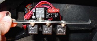
The fuel pump relay is located on the left side of the front passenger's feet, where three relays and three fuses are located next to each other.
After dismantling, we put it aside
The fuel pump relay is located exactly in the middle under the number “5”. The fuse number “3” is also located nearby.
Additional block
Functionality check
In order to check the fuel pump fuse, you just need to inspect it and, if necessary, replace it with a known working one.
There are several methods to check the fuel pump relay:
- The easiest way is to replace the old relay with a known good one.
- If you don’t have one at hand, you can use a regular multimeter.
How to check the EBN relay
In addition to the EBN circuit breaker itself, you need to check the fuse - it is located on the power line, located in the same block as the relay, but in its own location. Usually enclosed in a plastic box. Its composition is usual - inside the flask there is a sensitive low-fusible plate, a wire, which, when overheated (if there are surges or short circuits), melts and breaks, thus de-energizing the circuit and protecting the equipment. Pictured is Renault Safrane:
It is easy to check a fuse with a glass bulb in microcircuits - just look to see if the wire is broken. But in a car the body of the part is different, which complicates visual control. Therefore, it is advisable to check with a multimeter (by ringing for a break) or with a tester.
The method for checking the fuel pump relay with control is applicable to both it and the fuse. The tester will be a light bulb with a current of up to 0.25 A; a 12 V one will do (these are used to illuminate refrigerator chambers). The power should not be greater, as the control unit may burn out.
It is mounted instead of a relay, its wires are twisted to the power wires and inserted into the terminals in the socket. The ends leading to the light bulb can be soldered directly to the base; you can hold them with your fingers, but it will also be more convenient to buy a small socket, on which the wires are clamped with bolts.
We take out the relay. We connect the wires to ground and 87. When the engine starts, the light should light up and not blink - then the fuse is good. If not, then it is broken or there is a break in the chain. It is easy to dismantle - the plastic box snaps out of its seat. There is also a method with jumpers (discussed below).
Photo with instructions for BMW (also suitable for other models):
However, you can immediately check the fuse with a multimeter for a break, and if one is found, then replace it and see if the VT will work. If not, then that's the problem.
So, the main sign of a breakdown is that there is no buzzing from the pump after turning the ignition key, and the first thing to check is the fuse. For example, on the Lada Kalina and Granata it is on the F21 circuit (15 A), and the relay is K12.
Next, we will describe another algorithm of actions for checking the VT relay on the specified models:
- We activate the ignition.
- We remove the relay.
- We supply +12 V (we use a battery) to pin 11 of the diagnostic block or place a jumper between the terminals in the socket for pins 87 and 30 of the circuit breaker. You can take simple thick copper wires. If the pump is working properly, then it starts to work, the relay should be changed. If there is no start, then, without removing the jumpers, holding one control wire to ground, touch the second wire to the EBN supply wire; if there is no light, then there is a break in the circuit.
- We observe whether there is a buzzing sound from the pump.
What is the VAZ 2110-2112 fuse box?
It is not difficult to understand why they are needed. This protective element is found in almost any electrical circuit. It must protect the power source and electrical circuit of the VAZ-2110 from possible overloads and short circuits. Think about what would happen to your car if each of its individual electrical circuit elements were not protected?
The car's operation would be extremely unreliable. Any short circuit or overload in the electrical circuit of the VAZ-2110 would, at best, result in a simple failure of the vehicle, and in the worst case, failure of the battery and power supply circuit elements. That is why on VAZ cars fuses of the 2112 model, as in the top ten, are a key element of the electrical circuit.
Structurally, they are a small transparent plate with two legs for electrical contact. The product itself contains a number with the rated current. This means, if the load in the protected circuit of the VAZ-2110 rises above the specified Ampere value, the fusible insert inside the fuse will melt and break the power circuit. Naturally, after operation, the spent element should be replaced.
The safety block consists of more than just protective elements. The main relays are also located there. They are the actuator. Under the influence of the electromagnetic force created by the control signal to the relay coil, an entire group of contacts can be closed and opened at once.
This is especially important for control lines. For example, the electronic components of the circuit are not able to independently turn on a large load, so they do this using an electromagnetic relay. The same applies to turning the ignition key.
With one turn you turn on a huge number of devices and mechanisms independent from each other.
The same applies to turning the ignition key. With one turn you turn on a huge number of devices and mechanisms independent from each other.
Location of fuses on the diagram for VAZ 2110, 2111, 2112
Today we will look at the location of fuses in VAZ cars of the tenth family, namely models 2110, 21102, 21103, 2111, 2112. We will also show where the fuses and relays are located on the diagram and talk about the purpose of each of them and how to replace the fuses with your own hands. We will also touch on the most common problems with fuses among owners of these cars, diagnostic methods and replacement.
I would like to say that car electrical systems, in particular fuses and relays in the VAZ 2110, 21102, 21103, 2111, 2112, are quite reliable. The service life depends on operating conditions and timely diagnosis and replacement with high-quality components.
Let's figure out why fuses are needed in a car. First of all, they are responsible for the safety of the wiring and other systems of the machine.
It is important to understand that each specific fuse is responsible only for its task and in the event of a short circuit or failure, a fire is practically excluded. A specific fuse blows and this does not cause a chain failure of other systems
Depending on the problem of failure of any component or part of the car for which the electrician is responsible, you need to understand whether the car can be operated with this malfunction or not. The traffic rules contain a list of faults that you cannot operate a car with. If you discover, for example, that the headlights have failed or the wipers are not working at all, you should immediately correct the problem. Well, you can drive a car with non-working power windows. So…
Tips and tricks
When checking and/or replacing fuses and relays, it is important not to mix up the installation locations during reassembly. If the components in the fuse box are installed incorrectly, then various electrical equipment may become inoperable.
Due to the low cost of the relay and fuel pump fuse (about 1-2 USD for each element), it is recommended to completely refrain from installing various jumpers and other solutions unless absolutely necessary. Such methods allow you to bypass power to the pump, which significantly increases the risk of fire or failure of electrical equipment.
Finally, we would like to add that purchasing high-quality original parts guarantees their durability. The possibility that something in the pump circuit will burn out on its own for no reason is minimized. This recommendation fully applies to the fuel pump relay.