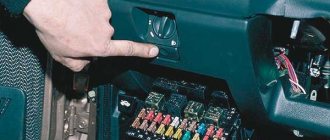
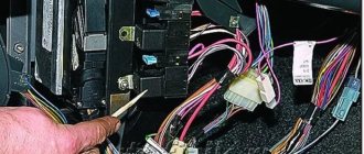
The engine control system of VAZ 2108, 2109, 21099 cars has three relays and three fuses that protect its electrical circuits. They are located in a separate fuse and relay box, which is located under the instrument panel on the right side of the driver under the storage shelf. The block is protected on top by a plastic cover attached to three self-tapping screws.
ECM relay VAZ 2108, 2109, 21099
— Relay for turning on the fuel pump (2).
— Relay for turning on the electric fan of the cooling system (3).
ECM fuses VAZ 2108, 2109, 21099
— Fuse (7.5A) of the control unit (ECU) and ignition module (6).
— Fuse (7.5A) of the winding for turning on the electric fan of the engine cooling system, the canister purge valve, air flow sensor, speed sensor, oxygen concentration sensor (5).
— Fuse (15A) of the fuel pump (4).
— Fuses are removed when repairing electrical circuits, relieving pressure in the fuel line, and measuring compression in the cylinders.
More articles on ECM VAZ 2108, 2109, 21099
If the starter of your car turns normally, but the car does not start, the first thing you need to do is check that the fuel pump is turned on. On domestic cars, its operation can be heard from the passenger compartment; when the ignition is turned on, a characteristic buzzing sound comes from under the rear seat or trunk. If the fuel pump does not work, you need to check the integrity of the fuses and the activation of the main relay of the engine management system and the fuel pump relay. On the VAZ-2107, VAZ-2108, VAZ-2109 and their modifications, relays and fuses are located on the shelf under the glove compartment or under it. On VAZ-2110 and similar ones, you should look in the heater console on the passenger side by unscrewing the fastening screws and removing the side cover. On GAZ cars they are located under the hood on the front wall of the cabin, closer to the passenger side.
Pinout and diagram of a fuel pump with a VAZ relay
The fuel pump on a car is designed to supply fuel to the combustion chamber. Its operation is controlled using a relay. On a VAZ (depending on the model), the fuel supply unit can be electrical or mechanical - it all depends on the fuel supply system. On a fuel-injected car, the fuel pump is located in the tank. When the ignition is turned on, voltage is supplied to the terminals of the unit and it begins to pump fuel. If the required pressure is created in the system, the relay automatically turns off the fuel pump - the engine is ready to start.
When the ignition is turned on, the relay creates pressure in the fuel lines by turning on the fuel pump (BN) for a couple of seconds. After this, the BN will work either when the engine is cranked by the starter, or when the engine is running.
Sometimes this system needs repairs - there is nothing complicated here, and the editors of the 2Skhema.ru website will tell you how to do it yourself. Let's start with the BN pinout, then we will indicate it on the diagrams and at the end there will be instructions for replacing the fuel supply elements.
Where is the fuel filter located?
The fuel filter (TF) on the VAZ-21099i is designed to clean gasoline from debris, dirt and various impurities; it is a monolithic structure with a rigid metal body and a filter element inside. The frequency of its replacement is every 20-30 thousand km of the distance traveled, also if the car begins to move jerkily, and diagnostics showed that the fuel pump is clogged.
It’s easy to find out where the fuel filter is located; to do this, you need to install the car on an inspection hole or a car lift. The TF is located on the bottom of the body, next to the rear beam and the gas tank, and is secured with a special clamp, which is tightened with a bolt and nut.
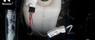
Before you start changing the filter, you need to relieve the fuel pressure, otherwise when you unscrew the fuel fittings, gasoline will splash under high pressure. You can relieve pressure in the line using a special nipple located at the rear of the fuel rail. Before starting such an operation, it is necessary to prepare a plastic container into which gasoline should be poured, then unscrew the safety cap.
To release the pressure, you can use a standard flat-head screwdriver; when you press the nipple valve, gasoline will come out of the system.
After removing fuel from the line, we proceed to replacing the fuel pump.
Related articles:
- The influence of the fuel vapor recovery system on the operation of the Lada Kalina engine. Modern technologies are developing, equipment is becoming more complex and sophisticated, and progress does not bypass motor vehicles. Carburetor cars were very simple, and understanding them [...]
- Front spar of the VAZ-2109 - replacement, repair, cost of work The VAZ-2109 is a car that does not have a strong body; iron corrodes quite quickly, and almost all body parts rust. Replacement of the front side member is required […]
- Features of replacing the VAZ-2114 oxygen sensor, signs and causes of malfunction In connection with tightened environmental standards, all cars began to be equipped with additional systems that reduce the toxicity of exhaust gases, and on almost every car with […]
Pinout of fuel pump VAZ 2107
1 – radiator fan drive motor; 2 – mounting block block; 3 — idle speed sensor; 4 – engine ECU; 5 – potentiometer; 6 – set of spark plugs; 7 – ignition control unit; 8 – electronic crankshaft position sensor; 9 – electric fuel pump; 10 – indicator of the number of revolutions; 11 – lamp for monitoring the health of electronic systems and the brake system; 12 – ignition system control relay; 13 – speedometer sensor; 14 – special factory connector for reading errors using the BC; 15 – injector harness; 16 – adsorber solenoid valve; 17, 18, 19,20 – fuse box for repairing the mounting block that protects the injection system circuits; 21 – electronic fuel pump control relay; 22 – electronic relay for controlling the exhaust manifold heating system; 23 – exhaust manifold heating system; 24 – fuse protecting the heater circuit; 25 – electronic air sensor; 26 – coolant temperature control sensor; 27 – electronic air damper sensor; 28 – air temperature sensor; 29 – pressure control sensor and low oil pressure lamp.
You can check the fuel pump on a VAZ 2107 simply by checking the voltage at its connection block with a tester. The presence of voltage will indicate a malfunction of the electric motor. Instead of a tester (multimeter), you can use a test lamp to diagnose a malfunction.
In the absence of one, this can be done by disconnecting the connection block for the fuel pump and fuel level control and applying voltage with wires from the battery to the place where the gray wire is connected +12 and to the place where the black wire is connected - minus. A humming pump will indicate a faulty fuse, power circuit or ECU.
New VAZ 21099 fuse blocks
Since 1998 they began to install fuse blocks 2114-3722010-60 - for cars with a high “torpedo”:
For cars with a “torpedo” from the VAZ 2115 - blocks 2114-3722010-10 and 2114-3722010-18:
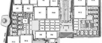
PSU fuses 2114-3722010-60:
Pinout and diagram of a new type of mounting block with an injection motor and a high panel:
Numbering of block pads (in the diagrams they are indicated by the letters “W” or “X”):
To find a break in a particular wire, it is not enough to know only the pinout of the block - you will need a detailed diagram with color coding of the wires.
Electrical diagram of a carburetor VAZ 21099 with a high instrument panel:
Pinout BN VAZ 2108, 2109, 21099
The fuel pump activation relay (2) is shown by an arrow.
1 — nozzles; 2 — spark plugs; 3 — ignition module; 4 — diagnostic block; 5 - controller; 6 — block connected to the instrument panel harness; 7 - main relay; 8 - main relay fuse; 9 — electric fan relay; 10 — controller power supply fuse; 11- electric fuel pump relay; 12 — fuel pump power circuit fuse; 13 — mass air flow sensor; 14 — throttle position sensor; 15 — coolant temperature sensor; 16 — idle speed regulator; 17 — knock sensor; 18 — crankshaft position sensor; 19- oxygen sensor; 20- APS control unit; 21 — APS status indicator; 22 — speed sensor; 23 — electric fuel pump with fuel level sensor; 24 — solenoid valve for purge of the adsorber; 25 — block connected to the ignition system harness; 26 — instrument cluster; 27 — ignition relay; 28 — ignition switch; 29 — mounting block; 30 — electric fan of the cooling system;
A - to terminal “B+” of the generator; B - block connected to block K of the ignition system harness; C - block connected to block L of the ignition system harness; D - wire connected to the interior lamp switch; E - wire connected to the white and black wires disconnected from the interior lamp switch; F - to the “+” terminal of the battery; G1, G2 - grounding points; K - block connected to block B of the front harness; L — block connected to block C of the front harness.
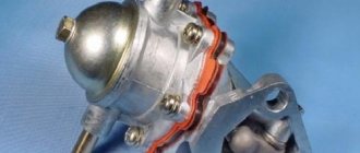
On “nines” with a mechanical fuel pump, the most common malfunction is wear of the fuel pump diaphragm, as a result of which gasoline will leak through the drainage hole in the housing when it operates. The second reason for the failure of such a fuel pump is wear of the pusher, which transmits force from the camshaft cam to the fuel pump drive lever.
Tips for motorists
VAZ-2109 passenger cars of the last years of production had injection engines, so on these “nines” an electric fuel pump was installed in the fuel tank. And on a small part of the VAZ-2109 with a carburetor engine still in use today, mechanical fuel pumps were installed.
Failure of the fuel pump on VAZ-2109i injection engines is determined quite simply, since when the ignition key is turned to the “ignition on” position, the driver simply will not hear the characteristic noise that the operating electric motor of the fuel pump makes. Typically, drivers of “nines” begin their search for the cause of a fuel pump failure by checking the condition of the fuse that protects this electrical circuit.
It is located under the front panel shelf, which is located below the glove compartment. When you unscrew the fastening screws, the block of three relays and three fuses on the wires will move lower, so it will be more convenient to work with it. You will need to check the rightmost fuse and the condition of its contacts. If a blown fuse is detected, it will have to be replaced with a new one. And also find the reason why he burned out.
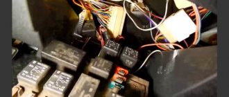
If the fuse is intact and the contacts are not oxidized, then the next step in troubleshooting is to check the functionality of the fuel pump relay. It is located in the same block as the fuse and is located on the far right. Drivers usually check it by replacing it with a known-good relay. If after such a replacement the fuel pump starts working, then you will have to purchase and install a new relay.
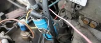
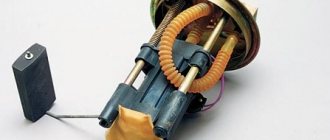
But when the fuel pump still continues to be “silent”, then you will need two wires four meters long. They are needed to check the condition of the fuel pump itself by connecting it to power directly from the battery. To do this you will need to: lift the rear seat cushion, remove the hatch cover, disconnect the plug block and connect the wires from the battery to the fuel pump terminals. There are three terminals in the block: one for ground, the negative one from the battery is connected to it, two more positive ones, for the fuel pump and the fuel level indicator in the tank.
If the fuel pump, when connected directly, works, then you will have to ring the wires going from it to the fuel pump relay, and if it does not work, then either replace it with a new one, or you will have to disassemble it and look for a fault inside the fuel pump.
On “nines” with a mechanical fuel pump, the most common malfunction is wear of the fuel pump diaphragm, as a result of which gasoline will leak through the drainage hole in the housing when it operates. The second reason for the failure of such a fuel pump is wear of the pusher, which transmits force from the camshaft cam to the fuel pump drive lever.
VAZ 2110 fuel pump pinout
If the fuel pump works directly when connected to the battery, then you will have to ring the wires going from it to the fuel pump relay, and if it does not work, then either replace it with a new one, or you will have to disassemble it and look for a fault inside the fuel pump.
Fuel pump characteristics
The technical characteristics of the fuel pump must correspond to those required by the manufacturer. Standard:
- rated operating voltage, V – 12;
- current consumption, A – 6.5;
- productivity, l/h – 60 (at a voltage of 13.5 V and a back pressure of 3 kg/cm2);
- weight, kg – 1;
- pump length, mm – 90.
The performance of the pump purchased for replacement should not be less than required. Otherwise, the engine will “triple” and the power will decrease.
Pinout BN VAZ 2113, 2114, 2115
— block headlights; — gearmotors for headlight cleaners*; - fog lights*; — ambient temperature sensor; - sound signals; — engine compartment lamp switch; — electric motor of the engine cooling system fan; — generator; — low oil level indicator sensor; — washer fluid level sensor; — front brake pad wear sensor; — wire tips connected to the common windshield washer pump**; — windshield washer pump; — headlight washer pump*; — wire ends for connecting to the rear window washer pump on VAZ-2113 and VAZ-2114 cars; — low oil pressure indicator sensor; — engine compartment lighting lamp; — wire lug for connecting to the wiring harness of the engine control system; — gear motor for windshield wiper; — starter; — a block connected to the wiring harness of the ignition system on carburetor cars; — coolant temperature indicator sensor; — reversing light switch; — low brake fluid level indicator sensor; - accumulator battery; — low coolant level indicator sensor; — relay for turning on fog lights; - mounting block; — brake light switch; — plug socket for a portable lamp; — hydrocorrector scale illumination lamp; — switch for the parking brake indicator lamp; — block for connecting a backlight lamp; — switch for instrument lighting lamps; - Understeering's shifter; - hazard warning switch; — front seat heating element relay; — ignition switch; — rear fog light circuit fuse; - fuse for the front seat heating elements; — door lock circuit fuse; — front ashtray illumination lamp; — ignition relay; - cigarette lighter; — glove box lighting lamp; — switch for the glove compartment lighting lamp; — heater fan electric motor; — additional resistor for the heater electric motor; — heater fan switch; - heater switch illumination lamp; — lamp for illuminating the heater levers; — gear motors for electric windows of the front doors; — power window switch for the right front door (located in the right door); — gear motors for locking front door locks; — wires for connecting to the right front speaker; — gearmotors for locking rear doors; — wires for connecting to the right rear speaker; — door lock control unit; — wires for connection to radio equipment; — headlight cleaner switch*; — rear window heating element switch; — relay for turning on the rear fog lights; — block for connection to the heating element of the right front seat; — rear fog light switch; — switch for the heating element of the right front seat; — fog light switch*; — switch for external lighting lamps; — left front seat heating element switch; — block for connection to the heating element of the left front seat; — wires for connecting to the left front speaker; — power window switch for the left front door (located in the left door); — power window switch for the right front door (located in the left door); — wires for connecting to the left rear speaker; — side direction indicators; — courtesy light switches on the front door pillars; — courtesy light switches on the rear door pillars; - lampshade; — ceiling lamp for individual interior lighting; — block for connecting to the wiring harness of the electric fuel pump; — trunk light switch; — instrument cluster; — trunk lighting lamp; — display unit of the on-board control system; - trip computer*; — block for connecting the wiring harness of the engine control system; — rear exterior lights; — rear interior lights; — pads for connecting to the rear window heating element; — license plate lights; — additional brake signal located on the spoiler.
Replacing an electric fuel pump on a VAZ
- Reduce pressure in the fuel supply system.
- Using the fuel supply hose tip clamp, disconnect 2 hoses in turn.
- Unscrew the 8 nuts around the circumference of the clamping ring and remove it.
- A wire with negative polarity is attached to one of the nuts; it must be removed carefully.
- We take the electric pump block out of the fuel tank, tilting it slightly, to keep the fuel level indicator sensor lever intact, otherwise it will produce incorrect parameters.
- Remove the sealing rubber ring of the fuel block. If its properties are lost, the product must be replaced.
- Install the pump in reverse order.
When installing fuel hoses, focus on the direction of fuel supply indicated by the arrows, and the installation arrow on the electric pump cover should point towards the rear of the car!
Work process
Electric fuel pump for VAZ 2110
The driver turns on the ignition switch, a signal is sent from the on-board computer to the electric motor of the pump, in which an electric charge occurs. A motor starts working inside the pump itself, creating a working pressure level in the fuel supply system in a few seconds. After three seconds, the on-board computer does not give a signal to start the engine, and the pump motor automatically turns off. At this time, you can hear the operation of the electric fuel pump. In the first seconds of the pump starting to operate, gasoline enters it through the tube. The fuel exits through a special one-way valve installed by the manufacturer, which traps debris and impurities.
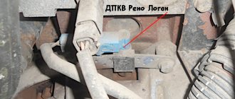
Where is the fuel pump relay located?
Where is the fuel pump relay located? The installation location of the relay varies depending on the make of the car. Most often, it is located under the hood, in the fuse and relay box.
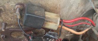
The fuel pump relay is designed in the circuit to prevent accidental application of high voltage to the fuel pump winding. The relay is standard and consists of a plastic body and coils with contacts. It is located in the car interior near the console. To access it, you need to remove the protection cover.
In appearance, it is a small box that resembles a “plug” with an American type of output. Each terminal has a marking that indicates the following: 31 – mass; 30– +12V constant (regardless of ignition); 15– +12 with the ignition on; 50– +12 when the starter is running; TD – signal from the ignition system; TF – engine temperature signal from the injection control unit KE. Outputs: 87 – supplies power to the fuel pump; 87H – oxygen sensor heating; 87V – turns on the starting injector.
Checking the fuel pump
So:
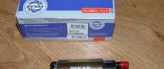
- Let’s immediately look at the two most common types of gasoline pumps, “Pekar” and DAAZ. They are installed on both rear-wheel drive and front-wheel drive cars. To check the serviceability and functionality of the entire fuel supply system:
- Remove the gasoline hose from the outgoing (discharge) fitting of the gasoline pump
- Then press the fuel pumping lever manually several times
- If the VAZ fuel pump is working properly, then a powerful stream of fuel should come out of the fitting
- If there is no stream, or there is a weak stream, perform a second check
To check the serviceability of the intake valve:
- We disconnect the fuel hose from the suction fitting of the pump (it turns out that now we have removed both fuel hoses from two fittings)
- Then we plug the suction fitting with our finger and press the lever for manual pumping several times
- At the same time, you should feel a vacuum on your finger (it should be sucked to the fitting)
- When there is a vacuum, this means that the fuel pump is working, look for faults in the gas tank or fuel lines
- If not, the fuel pump on the VAZ 21093 does not work, remove the pump, disassemble and change the intake valve
To check the exhaust valve for leaks:
- Place your finger on the hole in the injection fitting (the one that supplies gasoline to the carburetor), then press the lever several times to manually pump
- At the same time, a very noticeable stream of air comes out of the fitting hole, it pushes the finger away from the fitting
- If the stream is weak or absent, it means that the fuel pump on the VAZ 2109 does not pump, then remove the pump, disassemble and replace the exhaust valve
- If the filter is deformed or clogged:
- Remove the cap from the fuel pump, take out the fuel filter, clean it, rinse it in gasoline, then blow it with compressed air
- If the filter is deformed, then change it
- In the Pekar brand fuel pump, as well as similar pumps, the filter is removed by unscrewing the suction fitting from the cover, so you don’t have to remove the cover itself
- In case of malfunctions (leaky, torn) of the diaphragm:
A characteristic sign of such a malfunction may be the presence of fuel leaks on the fuel pump housing or the appearance of a gasoline smell in the engine oil. However, these signs may not appear:
- Remove the upper part (cover) of the fuel pump housing
- Take out his diaphragm assembly
- Unscrew the nut on the rod, then remove the diaphragms (there are three in total)
- Replace the diaphragms with new ones (you will need to purchase a repair kit)
- Then put everything back together, the diagram is in the photo below
Scheme of the diaphragm assembly
- The Pekar brand fuel pump has only one diaphragm.
- It can be removed after removing the cover.
- To disconnect the diaphragm assembly, rotate it 90 degrees.
If the valves are faulty, the VAZ 2109 does not pump the fuel pump, therefore:
- Remove the cap from the fuel pump, as well as the fuel pump strainer.
- Visually inspect the intake valve and fuel pump cavity
- Remove the upper body, inspect the exhaust valve
- When the valves are not pressed into the housing tightly or are not pressed tightly, or have lost mobility, then the pump must be replaced
- If blockages are found, they should be removed and then the housing should be blown out with compressed air.
- In the Pekar pump, both of its valves are located in the cover, so in order to assess their condition it is necessary to remove it from the body
- VAZ 21093 fuel pump does not work, if the pusher is damaged:
- Remove the fuel pump from the studs, while unscrewing the nuts that secure it
- At the same time, its gaskets, heat-insulating insert and pusher remain on the engine
- We rotate the crankshaft so that the pusher extends as far as possible
- You should measure how much the pusher protrudes above the plane of the topmost gasket
- The protrusion should be 0.8 - 1.3 millimeters
- When the protrusion of the pusher does not fit into the given size, then you should try to adjust it by selecting shims of smaller or greater thickness (depending on whether the length is not sufficient or it sticks out strongly) or change the pusher
- Replace only the outer thickest gasket located between the thermal insulation insert and the fuel pump
- Although repair kits for fuel pumps with ready-made gaskets are sold, you can also save money and cut it yourself from a piece of paronite
- If the spring under the diaphragm is broken:
- It is necessary to remove the upper part (cover) of the fuel pump housing, then remove the rod with diaphragms, carefully inspect the condition of the spring
- We replace broken, or compressed, lost elasticity
Fuel pump relay VAZ 2109 injector
The engine control system of VAZ 2108, 2109, 21099 cars has three relays and three fuses that protect its electrical circuits. They are located in a separate fuse and relay box, which is located under the instrument panel on the right side of the driver under the storage shelf. The block is protected on top by a plastic cover attached to three self-tapping screws. ECM relay VAZ 2108, 2109, 21099
- Fuel pump activation relay (2).
— Relay for turning on the electric fan of the cooling system (3).
ECM fuses VAZ 2108, 2109, 21099
— Fuse (7.5A) of the control unit (ECU) and ignition module (6).
— Fuse (7.5A) of the winding for turning on the electric fan of the engine cooling system, the canister purge valve, air flow sensor, speed sensor, oxygen concentration sensor (5).
— Fuse (15A) of the fuel pump (4).
— Fuses are removed when repairing electrical circuits, relieving pressure in the fuel line, and measuring compression in the cylinders.
More articles on ECM VAZ 2108, 2109, 21099
Hello everyone, in short, I arrived and parked the car, an hour later I go out and start it, and after a minute it stalls, well, when I start it, it won’t start. I’m starting to make a diagnosis, in short, the fuel pump doesn’t squeak, I changed the relay and previous ones to new ones - it didn’t help. Then I threw the plus directly - the gasoline started working. So now what's the problem? By the way, the immobilizer was disabled a long time ago.
Here's my wiring diagram
Comments 33
Is there a spark? Are the forces working?
The Akum comes with a thin wire from the ECU, there is a fuse on the wire (in the form of a black barrel), disposable, so try it or remove it or throw the wire from the Akum to the relays near the ECU
Check numbers 11 and 12 on the diagram, then the ground of the fuel pump, then check the voltage at the output of relay 11, pin 30, if there is voltage, check the voltage at the fuel pump chip. Doesn't the alarm block the pump?
no it doesn't block
Then check what I wrote above...
if the relay doesn’t click, or the signal from the brains doesn’t come to it, it’s a minus in my opinion, or there’s no plus, but the plus is supplied from the main relay...
Is it possible that you have a problem with your fuse block? The path burned out, because everything works straight
Which fuse box is there? They are not there.
Well then, try ringing the wires and the MB will block the signaling. If everything else is ok IMHO
It was like this, the relay did not click, the power supply to the pump was cut off. I probably spent a whole day searching, but in the end an electrician I knew tore out the parallel circuit from the secret. The point is, the previous owner installed secret locks before me, I removed them safely and drove for half a year without knowing any troubles. It turned out that the secrets also have a bypass circuit, which for some reason was not turned on before, just 2 wiring parallel to the brains. In general, climb under the torpedo and see what is connected to the braid in the notch, perhaps what is left from the old owners. If it’s not a problem to find the signal-secret blocks, then the outline is more difficult to find. Well, or as an option, the immobilizer was not completely turned off, but it’s better to take it to an experienced electrician)
Lada 2109
Removal and replacement process
Now let's look at the process of changing power supply fuses for the old and new types of VAZ 21099. As stated above, the replacement instructions will be relevant for both carburetors and injectors.
Released before 1998
- Open the hood and disconnect the negative terminal of the battery.
- Find your power supply, which is located under the windshield opposite the driver's seat. Press the latches securing the device cover. Dismantle it.
- On the back of the protective cover you can see a diagram showing the location of the PCB and the relay in the block. It also indicates which element is responsible for what.
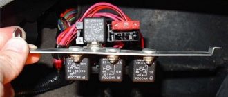
- If you need to replace a relay, then find the one you need and, shaking it up and down, remove it from its seat. Replace the burnt-out element with a relay with the same marking. Accordingly, observe the location of the contacts.
- If you need to replace the PCB, then first you should find out the reason for its failure. If the problem is in the element, then this is much better than if the problem lies directly in the wiring. In any case, if you decide to change the PCB, then keep in mind that the devices must be identical in nominal value, that is, the number indicated on the PCB body must be the same in both cases. Also, do not even think about installing a homemade element into the mounting socket.
- Close the power supply cover and connect the battery.
Released after 1998
As stated earlier, the instructions will be relevant for both carburetor and injection engines of the VAZ 21099.
- Open the hood and disconnect the battery: all work on the power supply must be performed with the battery disconnected.
- Locate the power supply installed in the engine compartment. As in the previous case, it is protected by a plastic cover that you need to remove to get to the elements. The fixing latches are installed on the side, closer to the car fender.
- Remove the cover. On its reverse side there is a diagram with the location of the relay and PP. Determine which element has failed so you can replace it. If the relay needs to be replaced, remove the component by rocking it from side to side.
- As for the fuses themselves, it is more convenient to remove them from the mounting socket using special pliers. By the way, tongs began to appear in blocks of a new type. It is also worth noting that the elements of the block are painted in different colors, but when replacing them, you should take into account not only the color, but also the denomination indicated on the case.
- Install the relay and PCB in reverse order. Don't forget to reconnect the battery.
Let's start with the fact that the fuel pump is controlled through a relay according to the following general scheme:
Also on some cars the device serves as a kind of engine speed limiter. If the engine speed approaches maximum and begins to exceed the permissible threshold, the fuel pump is switched off via a relay. The gasoline supply stops, the speed decreases, after which the element supplies power to the pump again.
If the relay malfunctions, then power may not be supplied to the fuel pump. The second option is that the pump hums or hums constantly, that is, it does not turn off a few seconds after the required pressure is created in the fuel line. In the first case, the engine often cannot be started because the pump does not pump and there is no gasoline in the fuel rail. In the second case, the fuel pump relay gets stuck (the fuel pump relay does not work) and the battery charge is consumed for the constant rotation of the fuel pump motor. Let us add that on some cars, starting the engine is possible even if there are certain malfunctions in the operation of the element, since the pump relay connection diagram allows the device to operate while the starter is cranking.
The fuel pump does not work.
If the starter of your car turns normally, but the car does not start, the first thing you need to do is check that the fuel pump is turned on. On domestic cars, its operation can be heard from the passenger compartment; when the ignition is turned on, a characteristic buzzing sound comes from under the rear seat or trunk. If the fuel pump does not work, you need to check the integrity of the fuses and the activation of the main relay of the engine management system and the fuel pump relay. On the VAZ-2107, VAZ-2108, VAZ-2109 and their modifications, relays and fuses are located on the shelf under the glove compartment or under it. On VAZ-2110 and similar ones, you should look in the heater console on the passenger side by unscrewing the fastening screws and removing the side cover. On GAZ cars they are located under the hood on the front wall of the cabin, closer to the passenger side.
What do you need to know about power supply maintenance and repair?
In terms of maintenance, the blocks are unpretentious. The car owner is recommended to periodically check the working condition of the safety elements. To do this, you need to open the cover of the unit, located in a special compartment behind the partition separating the car interior from the space under the hood. If burnt out components are found, these parts must be replaced. If you don’t have a whole device for this, then you need to purchase it. It is not allowed to install a piece of wire instead of a fuse. This may result in a short circuit and damage to wiring and equipment.
The device is located in a place where moisture can collect during rain. Water flowing down the windshield of the car enters the compartment in which the unit is installed. This compartment has a special drain hole for water, but its presence does not always help to avoid exposure to moisture on the power supply.
If the unit is not properly sealed, the liquid may destroy the unit's internal circuit board, requiring repairs.
The VAZ 2109 channel published a video in which the assembly procedure of the safety block was demonstrated in detail.
How to remove, disassemble and repair a power supply if it fails as a result of exposure to moisture:
- Open the cover of the product, having first turned off the ignition and reset the battery terminal of the car.
- Remove one by one all the parts and relays mounted in the block. Remember their location or take a photo of the power supply so that you don’t confuse anything during installation. Please note that 5 A fuses cannot be replaced with 15 A devices.
- Unscrew the bolts that secure the block to the car body. The mechanism can be additionally fixed using sealant. In this case, it is necessary to remove its remains with a stationery knife.
- After unscrewing the bolts, pull the block out of the seat. To do this, you need to disconnect all the plugs with wires connected to it.
- When you have the block in your hands, visually assess the condition of its board. Prolonged exposure to moisture can cause mold to form on the circuit. You should try to clean the unit board with a dry cloth or a special product that can be purchased at the store. Contacts damaged by moisture must be resoldered. To do this you will need a soldering iron with rosin and tin. After the contacts are re-soldered, the block is mounted in place. Also evaluate the condition of the plugs on the cables connecting to the device. If the contacts are damaged by moisture, they will need to be replaced.
- After installing the device in the mounting location, place all the parts, connect the battery and check the operation of the repaired product.
User Ivan Saichenko in his video showed how to solve the problem if all instruments and equipment in a VAZ 21099 car completely failed.
Hello guys! This is the first time I’m writing. In general, I bought a 99 injector and drove it for a drive, I started to act up a little, the fuel pump went away on its own, then the fuel pump failed and that’s it, I removed the fuel pump itself + and - put it on the battery, checked it works, the fuel pump relay does not work, the fuses are intact, the relay was swapped, nothing to do guys where to go??
Does the check light come on when you turn on the ignition when the relay does not work? Try moving the plugs, relays and fuses in the sockets near the ECU. Most likely the contact there is bad somewhere. But pay attention to the check light first. Also check the ground around the handbrake.
The check doesn't light up, I also think the ground may have come loose, the workers tried to take zero emotions from the mounting block, and if there is no ground, will the relay work?
Last edited by Evgeniy2020; 03.12.2019 at 20:18.
The relay may click and not work. Swap places
The check light does not light up, which means there is no power to the computer. And the reluchi turns on the ecu. How will it turn on if it doesn't work?
There is a separate + to the ecu from the terminal, there is a fuse there
And the other plus comes from the ignition switch.
The funny thing is that when everything was working, the check still didn’t light up when you turned the key, maybe the light bulb had burned out
Last edited by Evgeniy2020; 04.12.2019 at 09:23.
Changed places, zero emotions, only the starter relay clicks and that’s it
Last edited by Evgeniy2020; 04.12.2019 at 09:24.
The fuel pump relay does not turn on.
If the fuel pump does not work, then first of all you need to check the attraction of the main relay and the fuel pump relay. If the main relay does not click, then it is necessary to check its switching circuit and its serviceability. How to do this is described in the article the main relay does not turn on,
In the case when the main relay turns on, but the fuel pump relay does not, it is necessary to check the power at pins 85 and 86. When using a test lamp, its current consumption should not exceed 0.25A, otherwise damage to the controller may occur. If the control lamp does not light up on any terminal, then the relay is not receiving power. This may be caused by a blown fuse or a broken power cord.
In the case when the lamp burns brightly on one terminal, and at half-glow on the second, and the relay may be activated, you should remove the relay from the socket and connect terminals 85 and 86 with a test lamp. When the ignition is turned on, the control lamp should light up and go out after approximately 20 - 30 seconds. If the lamp lights up and there is poor contact in the connection between the block and the fuel pump relay. If the lamp does not light up, there may be a break in the wire connecting the relay to the controller or the controller itself may be faulty.
Signs of a fuel pump failure
A faulty fuel pump is quite easy to identify, since it is characterized by characteristic signs of failure. For example: while driving, the car suddenly stalls - after turning it on again, the engine begins to make uncharacteristic sounds, while the starter does not stop turning. After the car starts up, the picture repeats itself - the fourteenth engine stalls again. It is also possible that the car starts every once in a while - problems usually arise after sitting at neutral speed.
Let's determine the most typical signs of a fuel pump malfunction:
- The engine refuses to start. Of course, there can be many reasons for this problem - the same spark plugs, or the ECU, but the possibility of a fuel pump malfunction is also worth taking into account;
- The pressure level in the fuel relay differs from normal values;
- The motor is tripping. As a rule, if the fuel pump does not pump as it should, the engine begins to twitch quite noticeably because gasoline is not burned properly in the working cylinders;
- The engine growls at low speeds. One of the most truthful signs, which indicates either an immediate breakdown of the pump, or that the low-purity filter is clogged and the mesh needs to be replaced.
There are quite a lot of possible breakdowns that could cause the fuel pump to fail. The following parts of the unit design can present an unexpected surprise: fuse, fuel pump relay, ground, electric motor, contact system. Let's look at each of them separately.
Pressure level
In order to get most of the picture of what is happening, it is enough to measure the pressure in the fuel rail. For this, it is necessary to use a pressure gauge that has a small measurement range (preferably up to 7 atmospheres), since devices with a large range can produce significant inaccuracies.
Rail pressure measurement
Under the hood of the fourteenth there is a pressure fitting; unscrew its cap and connect the pressure gauge to it.
Normal indicators should be as follows:
- When the engine is idling – 2.5 kPa;
- At the moment of ignition - 3 kPa;
- With a pinched drain hose – 7 kPa;
- When gaining speed - 2.5-3 kPa.
If the pressure gauge needle does not move when the ignition is turned on, then the gasoline pressure regulator is most likely broken. When there is no change as the speed increases, the fuel pump itself has failed, but if the needle moves very slowly, which indicates that the pump is pumping, but poorly, the fuel pump screen is clogged.
How to test wiring with a multimeter
If the fuel pump does not work, do not rush to change it - perhaps the problem is in poor-quality wiring. There are 3 wires connected to the pump: to the gasoline level sensor, and positive and negative to power the motor.
No special tools are required to check the wiring - a regular 12-volt light bulb is enough. We connect the light bulb to the negative and positive wires of the pump, and turn on the car’s ignition - if the light blinks, then everything is fine with the wiring.
The fuel pump does not work, the relay turns on.
Checking relay power.
In the case when the fuel pump relay turns on when the ignition is turned on, but the pump itself does not work, you need to check the power at terminal 87 of the fuel pump relay. To do this, touch terminal 87 of the relay socket with the output of the control lamp connected to the vehicle ground, and the lamp should light up. If the lamp does not light, it means the fuse has blown or there is a break in the wire.
If there is power at terminal 87, you should remove the relay from the socket, and instead place a jumper between pins 87 and 30. In this case, if the pump and connecting wires are working properly, the pump should start working and if this happens, the relay should be changed. If the pump does not start working, then, without removing the jumper, you need to touch the power wire on the fuel pump with a test lamp connected to the vehicle ground.
How to check a fuel injector in 20 minutes
The fuel injector is responsible for delivering fuel to the engine and is controlled by the PCM as part of the fuel injection system. The fuel pressure supplied by the fuel pump is measured by the duty cycle computer, which depends on the engine load. This guide will show you how to test the start signal (ground) from the PCM, the power circuits, and the operation of the injector itself. To check the injector signal from the computer, a test light works best. You will need a voltmeter to check the resistance across the injector. Fuel may be present during testing, so normal fire precautions are required. Use protective gloves and goggles for safety. Test for FI systems only.
Checking fuel injectors
- Observe an audible click confirming the injector is working.
- Check trigger output from PCM
- Make sure the injector has power
- Check the coil winding resistance with a voltmeter
- Confirm the operation of the injector valve
- Inspect the injector body for leaks.
- Check flow and spray pattern
let's start
Simple test
- Start the engine and let it idle. Using a long metal rod, such as a screwdriver, touch the end of the screwdriver to the injector. Gently place your ear against the opposite end of the rod or handle to hear an audible click to ensure the injector is working.
Injector Circuit Power Test
- With the key in the on position, use a test light or voltmeter connected to the negative side of the battery. Carefully probe both sides of the injector wiring connector; one of the wires should respond, registering about 12 volts per meter or warning light illumination. If neither wire responds, check the fuel injector fuse in the parking sensors. If the fuse is good, a fuel injection wiring diagram is needed to help trace the wire and repair the connection. Seal test points with a slight touch of silicone rubber after testing is completed.
Injector Grounding Test
- The PCM closes the injector circuit to start the injector. The best way to do this is to monitor the pulse produced by the PCM. Attach the test light to the positive side of the battery and assist in starting or cranking the engine. Probe on the opposite side of the injector connector from the power circuit, you should observe the blinking warning light, which will respond to engine speed / load. If the engine runs and no pulse is observed, suspect a bad wiring connection or a faulty PCM injector driver, which warrants a PCM replacement. A shorted injector may prevent the injector driver from operating for additional injectors, disconnect all injectors and recheck the signal. If the pulse returns, connect the injectors back one at a time until the pulse can replace the shorted injector. If the engine does not run, check the crankshaft angle sensor, which the computer uses to open the injectors (Note: The crankshaft angle sensor will not set a trouble code in most cases).
Checking the fuel injector winding (key off)
- Using a voltmeter, set the value in ohms. This test can be performed with the injector installed or not installed.
- Remove the injector electrical connector
- This will expose the injector electrical terminals.
- Connect the voltmeter leads to the terminals; the polarity of the wires does not matter. This test provides a baseline resistance value for all injectors, the service manual also contains this information. Most injector readings should be between 11 and 24 ohms. Fuel injectors should be tested cold unless otherwise specified, temperature fluctuations will change the readings. If the Test shows high resistance or an open circuit the injector needs replacement.
Jet Spray Test
- For this test the injector must be removed. Inspect the injector body for leaks and electrical connectors for corrosion.
- The valve and spray pattern are the most important part of testing a fuel injector. A valve test can be performed with the injector still installed using the fuel pressure sensor while hot wiring to keep the fuel pump on. Carefully connect the 12V power source (power supply and ground) to the injector, you should be able to see the sensor oscillate as you connect and disconnect the circuit if the injector valve is working and not clogged.
- To check the spray pattern of the injector, it must be removed. Apply compressed air to the injector inlet. Connect 12 volts and ground to the power supply for the injector. Compressed air must be released from the exhaust valve with traces of fuel still remaining from the injector (use fire precaution). Observe the pattern, which must be stable if the pattern The muted injector must be replaced.