This car model was designed on the basis of the 967 model, which was produced for the military industry and had unique characteristics, it was an amphibian with a propeller, the ability to be dropped with a parachute and other characteristics that are not needed in civilian use. The main advantage is that the wiring of the LuAZ 969 is simple, and it is no different from the military version, so it’s not difficult to understand it.
A simple and very passable car is indispensable for off-road use.
Electrical wiring of LuAZ 969 - important features of the system that you should know
This car model was designed on the basis of the 967 model, which was produced for the military industry and had unique characteristics, it was an amphibian with a propeller, the ability to be dropped with a parachute and other characteristics that are not needed in civilian use.
The main advantage is that the wiring of the LuAZ 969 is simple, and it is no different from the military version, so it’s not difficult to understand it. A simple and very passable car is indispensable for off-road use.
LIGHTS
The headlights are equipped with a semi-dismountable sealed optical element, consisting of a reflector, diffuser glass and a flanged double-filament lamp.
Replacement of headlight bulbs must be done in the following sequence:
- remove the outer rim 1 secured with screw 2
- slightly unscrew the screws and remove the optical element, which is secured in the headlight by the inner rim 4;
- remove cover 13 with contacts;
- change the lamp;
- install the cover with contacts, the optical element, secure the inner and facing rims.
Adjusting the headlights FG 122 BV1
FG 122 BV1 headlights with European asymmetric low beam light distribution have a sharp boundary between the light and dark zones. Therefore, headlights must be adjusted very carefully so as not to dazzle oncoming drivers.
To adjust the headlights you need to:
- Place the equipped car with the driver on level ground against the screen located at a distance of 7.5 m from the car.
- Turn on the low beam and rotate two (on each headlight) adjusting screws 9 located at an angle of 90°. install the optical elements so that the boundary between the illuminated and unlit areas runs along line 2, and the inclined segments emerge from the intersection points of lines A and B with line 2, marked in the figure with the sign Each headlight is independently adjustable, and the light from another headlight should not illuminate the screen .
Features of wiring in this model
Let us note right away that in the production of the cars in question, economy has always been a priority, so you can find models with one drive axle (there were simply not enough of these units at one time) and other solutions that reduced the cost, but negatively affected the reliability and durability of the structure.
The following factors can be noted:
- Most cars were equipped with a generator without an integrated board; it did not differ in power, so when idling, most often the battery was not charged, which had a very negative impact on the operation of the battery and sometimes, especially in the cold season, the battery could simply run out.
This diagram is valid for all cars manufactured from March 1981 to August 1986, equipped with a generator without an integrated board
- But generators with an integrated circuit worked much better; they were distinguished by better charging and stable operation of the design. The wiring diagram is similar to the one above, the only difference is in the generator unit. You can easily see the difference yourself by comparing the diagrams in the photo; the generator is indicated by the number 8.
An improved version of the generator caused changes in the circuit
Advice! Some car owners include more powerful generators in this scheme; this provides brighter light and stable battery charging at any speed.
- The wires themselves are not reliable and over time they begin to burn out, rot, or the insulation simply dries out and collapses. There are some simple tips on how to extend the life of the system with your own hands, but this will require time and effort - you need to lay all the harnesses in special corrugations and protect all contacts by installing high-quality terminals and protecting them with heat-shrinkable tubing.
- The electrical wiring of the LuAZ requires constant inspection in order to identify faults at the stage of their development, since if you get stuck in the middle of off-road conditions, the work will become much more complicated.
- In the nineties, cars began to be equipped with ignition switches without steering column locking , which again caused a change in the circuit, but this is not so fundamental. In general, it can be noted that the design has remained virtually unchanged, therefore, having understood one modification, you can easily understand all the others.
- In order to better understand which electricity consumers are included in the system, look at the circuit diagram below. This is a kind of instruction that will help you understand how the circuit works and what is included in it.
From this picture it is easy to understand the features of LuAZ electrical equipment
Studying car electrical circuits
A minimal concept of the action of electric current is enough to understand how an electrical circuit works in a car, in a country house or in a factory. In a book on auto repair, symbols are usually written after the main diagram; there are also digital footnotes for convenience and quick reference.
When studying the circuit, you must have a multimeter.
It should measure quantities such as:
- voltage;
- current;
- resistance.
Each machine sensor must have certain parameters during operation; if they do not match, the electrical equipment will not work correctly.
The electronic circuit consists of:
- power source - it can be a battery or a generator - you need to start reading the diagram from them;
- electrical circuits that transmit current;
- control devices that close or open wiring;
- consumers of electric current.
Control equipment includes:
- relay mechanism;
- switches;
- end elements;
- egnition lock.
The main consumers of electrical energy in a car are:
- lighting network;
- heating (seats, windows, mirrors);
- dashboard;
- car security system.
An example of reading the diagram with your own hands if the car does not start:
- Using the diagram, we determine the color and marking of the conductors for the ignition system.
- We put the ignition key in the on position and measure the voltage value on the ignition unit with a multimeter. If there is voltage, the control unit itself is faulty; when the value on the device is 0, then the reason is in the appropriate wire.
After eliminating the causes, repeat measurements must be taken.
What should you consider?
On the diagram that comes with the car, the color designation of the wires usually matches the color of the car's electrical circuits.
When deciphering the scheme, you need to consider some points:
- The conductor can have one or two colors (be primary or secondary). The main colors are black “-” and red “+”. Transverse or longitudinal strokes are applied to additional ones.
- When two or more cables are placed on the same bundle and have the same markings, this means that they have a galvanic connection.
- If the conductor enters the bundle, it should have a slight slope to the side where it is located.
- Wires with black color are intended for connection to ground.
- There are symbols on electrical circuits that help determine the location of connection to the devices.
- The numbers on the mechanisms must correspond to the numbers in the diagram.
- The numbers indicated in circles indicate the connection of the cable with a “minus”. The combination of numbers and letters must match the plug connections.
The video shows graphic letter symbols. Filmed by chipdip channel.
Tips for Beginners
The main rule is compliance with safety precautions. When working with measuring instruments, it is necessary to take into account the measured limit in advance, measuring values without shorting the probes of the device.
Some features of repair work
If you have any malfunctions, you should fix them immediately. The work is not complicated, because there are no electronics in the system; we will consider only the most general recommendations, without delving into the process.
Maintenance
For work, you will need a simple set of tools and a tester, with which you can quickly and accurately diagnose the system and check the presence of current in a particular node.
In general, here are some tips:
- If the generator does not provide high-quality charging, it is best to replace it, and there can be many options - from VAZ units to foreign cars, the main thing is to choose the optimal configuration of the equipment so that you can get by with a minimum number of alterations, most often you need a bracket, the rest is adjusted locally.
If you are installing a more powerful generator, use this circuit
- When replacing individual cores, be sure to follow the color coding, otherwise it will be difficult to figure out what goes where. That is, if you change the red wire, then replace it with a new product of the same color. When the required option is not available, you can temporarily use what you have, but then be sure to replace it with the correct one.
This connection is not allowed
- Pay special attention to all connections, as they are the most common cause of malfunctions. Twists and electrical tape are unacceptable; you must purchase crimping pliers, install terminals on all ends of the wires, and cover the crimping area with heat-shrink tubing . In some cases, you can make a connection using a soldering iron, but after that it must be carefully tinned and covered with the same heat shrink.
This is what a correctly assembled contact looks like
Replacing electrical wiring
If the LuAZ wiring is in a very poor condition, then it is easier to replace it completely than to work with individual components.
The following can be noted on this issue:
- Finding an original kit is often very difficult, so as a way out of the situation you can use a ready-made wiring kit from a VAZ 2106. It is ideal for doing the job; you just need to understand the diagram in order to understand where each node should be connected. The length of all the harnesses is quite sufficient, and the price of this option is quite affordable.
What you need to know to build the correct website structure
Let’s move a little away from the “WordPress Training” blog, let’s talk about what a site structure is, how to form and create it.
So, let's draw up a small action plan, perhaps it will speed up your search for the necessary information (most likely you have already read something about the structure of the site, and you do not need to re-read everything again).
- What is the site structure;
- requirements for the site structure;
- types of structure, examples in the form of diagrams;
- external and internal structure of the site;
- how to properly change (remake) the structure of the site;
- checklist “WordPress Training” - what, how and why changed after changing the site structure.
What is site structure
The correct site structure is a system for arranging site pages according to a clearly formed logical scheme; the structure can be defined as the hierarchy of all site pages, their belonging to certain directories and folders.
In the abstract, the structure of the site can be described as follows:
- Where am I now (login page);
- where can I go (transition);
- relationship between categories.
When forming a structure, it is worth understanding the desires of potential visitors, what they will look for, and what information interests them.
The structure of the site is the way the user obtains the requested information. Here you can go very deep into SEO (keys, anchors, linking), but now the point is to understand what the site structure is, so I won’t do that. Let me say briefly that the better the structure is built, the better for you and your clients (visitors). It is easier for visitors to find information of interest and move from one page to another.
This way we will get an excellent structure for an online store, where all the pages of the site (articles, products, delivery form) are clearly laid out in their places.
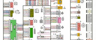
Connection diagram for generator LuAZ 969m
Click to enlarge diagram
I – Low beam; II – High beam; III – Sidelight and rear marker lamp; IV – Direction indicator; V-Brake light;
1. – Additional side direction indicator; 2. – Front right side lamp and direction indicator; 3. – Headlight; 4. – Connecting block; 5. – Front left parking light and direction indicator; 6. – Sound signal; 7. – Oil pressure gauge sensor; 8. – Location of the oil temperature indicator sensor; 9. – Generator; 10. – Ignition distributor; 11. – Connecting block; 12. – Starter; 13. – Spark plugs; 14. – Battery; 15. – Mounting fuse block; 16. – Battery switch; 17. – Electric windshield wiper motor; 18. – Engine compartment lamp; 19. – Relay regulator; 20. – Starter blocking relay; 21. – Relay for signaling the health of the brake system; 22. – Additional starter relay; 23. – Electric motor of the windshield washer pump; 24. – Ignition coil; 25. – Electromagnetic valve EPHH; 26. – Microswitch EPHH; 27. – Stop light switch button; 28. – Lamp in the interior lamp; 29. – Electronic unit, EPHH control; 30. – Plug socket; 31. – Direction indicator relay; 32. – Hazard switch; 33. – Central light switch; 34. – Three-lever steering column switch; 35. – Fuse; 36. – Bimetallic fuse; 37. – Fuse; 38. – Fuse; 39. – Ammeter; 40. – Instrument lighting bulbs; 41. – Indicator lamp for signaling the serviceability of the brake system; 42. – Turn signal control lamp; 43. – Oil pressure gauge (pressure gauge); 44. – Push-button bimetallic fuse; 45. – Speedometer; 46. – High beam warning lamp; 47. – Oil temperature indicator; 48. – Rear axle differential lock control lamp; 49. – Fuel level indicator; 50. – Rear axle differential lock warning lamp switch; 51. – Switches for signaling the serviceability of the brake system; 52. – Reversing light switch; 53. – Push-button bimetallic fuse; 54. – Fuel level sensor; : 55. – Horn contact; 56. – Ignition switch; 57. – Rear light; 58. – Reversing lamp; 59. – License plate lamp lamp; 60. – Heating installation; 61. – Heater temperature switch; 63. – Heater glow plug; 64. – Heater fan electric motor; 65. – Heater fuel metering solenoid valve; 66. – Electric fuel pump for the heater; 67. – Heater warning lamp; 68. – Heater control spiral; 69. – Connecting block; 70. – Heater switch;
Did you like the article? Follow our channel for new ideas of useful car tips. Subscribe to us in Yandex.Zen. Subscribe.
There was a huge demand for mini-compact off-road trucks, especially among residents of rural areas. Therefore, the entire chassis structure, power unit, electrical wiring of the LuAZ 969 and other elements were designed as simple and accessible as possible for self-service of the vehicle by its owners in the field.
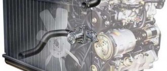
HEATING
What is a contract gearbox
The heating system operates independently of the car engine, which allows it to be used to heat the body when the engine is not running.
Use of the heating system when the engine is not running should be short-term, as the battery may be discharged.
The installation is powered by the same gasoline as the car engine. Rules for turning on and off the heating installation. You can turn on the heating system both when parked and while driving. To enable it you need:
- Pull handle 8 of the switch towards you until the first click is heard.
- Wait 30 seconds, and then move the handle to the second position, pulling it towards you until it stops.
- Monitor (within 45-60 s) the moment when indicator light 20 with a green light filter on the instrument panel lights up. Illumination of the control lamp and its continuous burning indicate normal operation of the heating installation. If the control light does not light up within 1.5 minutes after turning the switch to the second position, the heating installation should be turned off, the fault should be identified and eliminated. To turn off the heating installation, the switch handle must be pushed all the way away. In this case, the control light continues to light for 3-5 minutes and then goes out.
The heating system can only be put back into operation after the indicator light goes out.
To ensure heating of the body and blowing of the windshield, handle 7 of the damper axis must be in a horizontal position.
When the damper axis handle is in a vertical position, the engine will be heated.
The supply of heated air to the area where the driver and passenger’s feet are located or to the windshield is adjusted using handle 17 of the distributor damper.
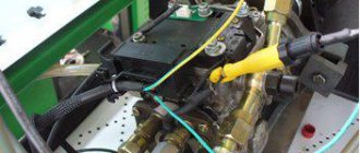
The heater is powered by an electric fuel pump BN-200A2, installed in the engine compartment under the heating installation.
The heating system switch has three switch positions:
- off (handle recessed completely);
- start-up (electric motor, heater glow plug and control spiral included);
- fuel supply (additionally included solenoid valve and solenoid pump).
Maintenance of the heating installation is carried out seasonally (in preparation for autumn-winter operation), and also as needed.
Seasonal maintenance of an electromagnetic fuel pump:
- remove from the car and clean from dust and dirt;
- remove the cover with fittings, rinse and clean the valves;
- if necessary (in case of interruptions in the operation of the pump), remove the cover of the contact system and check the condition of the contacts;
- restore the elasticity of the diaphragm (stretch it with your fingers);
- clean and rinse the sediment filter.
Seasonal heater maintenance:
Gasoline supply regulator. Rinse the filter, clear the float chamber of sediment, check the tightness of the shut-off needle, and blow out the nozzle with compressed air. Heat exchanger. Clean the glow plug from carbon deposits and blow it with compressed air. Blow the heat exchanger with compressed air through the spark plug hole to remove soot deposits. If there is a lot of soot in the exhaust pipe, you should completely remove the heat exchanger and, by tapping the body with a copper object, knock off the soot and blow it out with compressed air. Clean the drain pipe using a metal cleaning rod and also blow it out with compressed air. When installing a glow plug into the chamber, the axis of the spiral must be parallel to the axis of the heater. Gas outlet. Clean from dust and soot
Pay special attention to the safety of the metal-asbestos gasket between the exhaust pipe flange and the gas outlet. Blow out the fuel supply line and drain hose with compressed air, being sure to disconnect it from the regulator.
The following types of maintenance are performed as necessary:
- Clean (bleed) the nozzle by first unscrewing it from the gasoline supply regulator.
- Clean the glow plugs if carbon deposits form.
- Clean the heat exchanger and gas outlet from soot.
- Remove the electric motor, check it, lubricate the bearings.
- Wash the collector with gasoline or alcohol.
It is advisable to carry out troubleshooting and maintenance at a service station.
Owner restrictions
Like most Soviet-era cars, civilian versions of the cars were a continuation of military strategy:
- Even when in use by ordinary citizens, in the event of hostilities, cars were involved in combat missions;
- Each car was registered with the local military registration and enlistment office.
For reference: despite this prospect of possible mobilization, there were a lot of people who wanted to purchase an all-terrain vehicle. In the period from 1980 to 1989 alone, more than 130 thousand LuAZ 969 cars and its comfortable modifications with the “M” index were produced and sold.
Electrical circuits? - even a schoolboy can figure it out!
When I first encountered a schematic electrical diagram of a car, I realized that the principles of its construction and the designation of elements on it are standardized, and those elements that are present in all cars are designated the same way, regardless of the car manufacturer. It is enough to figure out once how to read such electrical diagrams, and you can easily understand what is shown on it, even if this is the first time you have seen a specific diagram from a specific car and have never even climbed under the hood of it.
Graphic designations of circuit elements may differ slightly; in addition, there are black and white and color versions. But the letter designation is the same everywhere. In addition to schematic electrical diagrams, it is useful to have diagrams that indicate the physical location (in space) on the body of various harnesses, connectors and grounding points - this will help you quickly find them. So, let's take a look at examples of such circuits, and then proceed to describe their elements.
An example of a car electrical circuit diagram
The circuit diagram does not indicate the physical relative positions of the elements, but only shows how these elements are connected to each other
It is important to understand that if two elements on such a diagram are shown next to each other, on the body itself they can be in completely different places
Schematic arrangement of electrical components on the body
Such a diagram carries another type of information: the routing of the cable braids and the approximate location of the connectors on the body.
Three-dimensional accurate diagram of the location of electrical components of the car
There are also diagrams that show exactly how and where the cable routes go in the car body, as well as grounding points.
Ignition system features
Since the civilian version of the car could not swim, the ignition systems were designed according to the classical scheme:
- Battery-coil design with one spark plug per cylinder;
- The battery is standard 6ST-55;
- Alternating current generator G-501 (or G-502 on modifications);
- Rectifier unit BVG-2A;
- Blocking relay;
- Fuses (6 pcs).
Also on the instrument panel there are 2 thermometallic fuses with a nominal value of 20A for protection:
- Heater electrical circuit;
- Lighting of the body and engine compartment;
- Plug sockets;
- Sound signal;
- Brake alarm systems (see also wiring diagram Niva 21213).
Advice: If the protection is triggered, it is necessary to determine the cause of the failure, eliminate it and restore the circuit by pressing the thermal fuse button on the instrument panel.
A bimetallic fuse is also used to protect the windshield washer and wiper circuit. It is installed under the hood and has a response threshold of 3.5A.
CIRCUIT BREAKERS
The following fuses are used in the vehicle electrical system:
- two thermobimetallic push-button type with a rated current of 20 A to protect the circuits of the heating system, body and engine compartment lighting, power socket, horn and brake warning system; installed on the instrument panel;
- three fusible fuses with a rated current of 6 A to protect the power circuits of instrumentation, a flashlight and a reverse switch and a turn signal relay (separately for the right and left sides), installed on wires under the instrument panel;
- thermobimetallic with a rated current of 3.5 A to protect the power supply circuit of the electric motors of the windshield wiper and washer; installed in the engine compartment on the bulkhead;
- a block of six fuses; installed in the body on the left side under the instrument panel.
Purpose of fuses:
- fuse A (8 A) - circuits of the sidelight and rear light of the left side (side marker), license plate lamp;
- fuse B (8 A) - circuits of the sidelight and rear light of the starboard side (side marker), lighting of instrumentation;
- fuse B (16 A) - left headlight high beam circuit;
- fuse G (16 A) - circuit of the main beam of the right headlight and the control lamp for turning on the main beam of the headlights;
- fuse D (8 A) - left headlight low beam circuit;
- fuse E (8 A) - low beam circuit of the right headlight.
Before replacing a blown fuse, eliminate the cause that caused its failure.
Thermal fuses are activated by pressing a button.
STARTER
Installed on the right side of the engine.
Starter Maintenance
During operation, it is necessary to periodically check the condition of the clamps of the starter traction relay wires and the fastening of the starter to the engine.
Every 36,000 km, you need to remove the starter from the engine to thoroughly check and replace worn parts and components. It is recommended to carry out this work in special workshops or service stations.
If there are malfunctions in the operation of the starter, it is recommended to remove it, disassemble it and eliminate the malfunction.
To remove the starter, you need to disconnect the wires from the starter, unscrew the two nuts of the starter mounting studs, move the length of the starter studs towards the timing gear cover and remove it. Installation of the starter must be done in reverse order.