The Chevy Niva has a very nice and convenient steering column switch compared to VAZ cars of the ninth and tenth families. It not only looks better, but also works quieter, and the key strokes are shorter than those of the “nine”. Accordingly, it has softer shifts, which is why craftsmen immediately began installing this product on other Lada cars. In some cases, the replacement is quite simple, in others, electrical skills will be required.
Disassembling the steering column turn signal switch Chevrolet Niva
08/02/2019 Niva
Our prices fluctuate quite significantly from 25 to hryvnia. This office is Ukrainian, but the high-quality cardboard packaging does not tell where these switches are made. Probably in China.
To replace it, you need to unscrew the 5 self-tapping screws that hold the steering shaft housing together. Next, remove the old switch and install a new one in its place.
Disassembling the steering column turn signal switch Chevrolet Niva
If not a single self-tapping screw is lost, then the turn and light switch lever on a Chevrolet Niva will change in no more than 15 minutes. Mileage mileage.
Chevrolet Niva turn switch It is clear that replacing the switch solves this problem and is not difficult. Chevrolet Niva turn switch, for your consideration, I present my experience in the execution of the said part. Looking ahead, I’ll say that: A I took it apart, B I fixed it. And now let’s talk about everything in order: The removed steering column cover greeted me with chipped fasteners on all fronts. The lid fits quite tightly and opening was accompanied by the fear of breaking it to the nuclear granny, but unhealthy interest and brute physical force once again drowned out the voice of reason and as a result the lid was removed.
Light and turn switch lever
The handle is removed from the groove by a movement exposing the contacts. An inspection showed that everything inside the box looks more than decent and even the lubricant tastes the same as in the good old days.
The desired culprit turned out to be the switch handle itself, namely the part that contacts the high beam activation mechanism - it, being made of metal, rubbed all the way to the spring return rod, and even scratched it. My poor calculator was never able to capture the essence, but if you look closely, you can see the Chevrolet Niva turn switch on the metal part of the handle, but it’s not there. Because of this selection, the high beam switch was not pressed.
The principle of operation of the mechanism as I understand it is described below. Once the enemy has revealed himself, it is time to strike back.
At first the thought came to me to simply turn the piece of iron over to the other side. It is held on by a pin that needs to be knocked out.
To do this, I ground the tail of the nano tap to the appropriate size and hit it with a hammer a couple of times. Then the handle can be easily removed when pulled out. The statement is also true for the windshield wiper mode switch.
If, as a result of diagnostics, it turns out that one of the steering column switches has failed, you need to purchase a new part, catalog number, or install it on the car, following this algorithm: Release the steering wheel adjustment switch and move the column to the lower position - for convenience .
Disassemble the plastic cover of the steering column, which consists of two halves.
To do this, use a screwdriver to unscrew several screws that connect them. Disconnect the connectors from the old key and pull it out of the socket, bending the plastic latches. Attach the connector to the new part and insert it into place.
Place the plastic casing and connect the battery. Where do the keys go? Steering column switches from a Chevy Niva car, with varying degrees of complexity, can be installed on the following cars: On all cars of the ninth and Chevrolet Niva turn switch family, keys from a Chevy Niva are installed almost without problems.
This is interesting: Checking the level and changing the oil in a Chevrolet Niva manual transmission
Positions of the gazelle steering column switch:
- 0 - disabled
- I - slow (one click down)
- II - fast (two clicks down)
- III - intermittent (one click up)
- IV - washer (handle towards you)
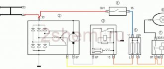
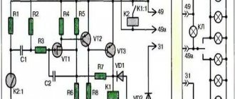
The second modification option using relay 524.37 47 Relay 524.37 47 compares favorably with 522.37 47 in three parameters:
- has a body half the size due to the fact that it consists of almost one chip
- The pause countdown in intermittent mode begins from the moment the brush motor stops (when contact 31B of the relay is connected to ground through the contact group in the wiper unit)
- the pause value can be changed from 4 s to 15 s (or more if desired) with a variable resistor R=10k (see Fig. 3), which can be output to any convenient location. In principle, you can connect this relay without a resistor, then this will be the circuit in Figure 2.

I highly recommend the second modification option. I myself am just about to start converting the first option into the second.
If you marked something wrong (after all, I did it a year and a half ago, maybe I got something mixed up), don’t judge strictly, but it’s better to call the contacts yourself before assembling.
Do-it-yourself Chevrolet rocker adjustment: instructions
To set up the scenes you need to perform a number of actions.
- 1st gear does not engage at the gearbox. To turn it on, you need to start the engine, moving the gearbox lever until the car starts moving. Next, turn off the engine while 1st gear is engaged. You need to place shoes or wheel chocks under the tires, not forgetting the parking brake.
- Next, you will need to lower yourself into the hole to unscrew the clamp bolt of the rocker itself.
- Now you need to find the plastic traction lock in the Chevrolet Niva interior and move it to the far left position.
- Next, you need to once again lower yourself into the inspection ditch to tighten the loosened clamp bolt.
So, the gearbox traction adjustment can be considered complete. Now it’s worth checking the functionality of the part. It happens that this process does not help, there is no result, and removal and, therefore, complete repair of the component is required.
Replacing the turn switch
To figure out how to install steering column switches from a Niva Chevrolet on another car, you must first understand how to change them on your “native” car. The Lada Kalina car also has keys of this modification.
Switches for light alarms and windshield wipers of the VAZ 2131 (Lada Kalina) are considered quite reliable products and function flawlessly for many years. The first problems with them were recorded after a run of 120 thousand km. This does not take into account operation in extreme conditions on dusty dirt roads, where all electrical parts wear out faster.
A failure of the turn switch on a Chevrolet Niva is often confused with a breakdown of the relay responsible for the operation of the corresponding light signals. The relay also fails rarely, but is cheaper than the keys. Therefore, in the event of a failure, it is better to start troubleshooting with the relay, provided that the fuse is in order. The statement is also true for the windshield wiper mode switch.
If, as a result of diagnostics, it turns out that one of the steering column switches has failed, you need to purchase a new part (catalog number 21230-3709330-00-0 or 2123-3709330) and install it on the car, following this algorithm:
- Just in case, disconnect the battery by disconnecting the ground contact.
- Release the steering wheel adjustment lock and move the column to the lower position for convenience.
- Disassemble the plastic cover of the steering column, which consists of two halves. To do this, you need to use a screwdriver to unscrew several screws that connect them to each other.
- Disconnect the connectors from the old key and pull it out of the socket, bending the plastic latches.
- Attach the connector to the new part and insert it into place. Place the plastic casing and connect the battery.
Mechanism problems
After the procedure for adjusting the traction of the Niva Chevrolet gearbox, faults continue to appear? Pay attention to them:
- free movement of the transmission lever increases;
- speeds do not change;
- difficult gear shift;
- switching on another gear or there is no possibility of switching gears.
When these problems are identified, there is a need for significant action, expressed in the repair or replacement of the scenes. However, to actually carry out such activities, the mechanism must be removed.
Transmission linkage: removal
The rocker on a Niva Chevrolet SUV is removed in the following order:
- Open the hood of the car and find the clutch tip of the lever, as well as the gearbox linkage. The rod has a turnbuckle with a protective cover that will need to be removed.
- In the Shnivy interior, remove the trim of the gearbox lever using a screwdriver. You should be careful not to damage the latches.
- Turn the cover the other way, and then cut the fastening clamp. Next you need to remove the cover from the lever.
- Remove the front of the floor tunnel lining.
- Unfasten the fasteners from the lever and remove the axle.
- Remove the shift lever by moving it up, and the remaining rubber cuff must be returned inside the removed lever.
- Remove the lever housing fixing bolts and remove the rocker.
- Remove the rod (rubber sleeve) from the shaft.
- Observe the rod for damage or defects. This way it will be possible to determine whether the backstage requires repair or replacement.
Replacement should be carried out if there is a gap in the hinges or serious wear of the play under the axis of the speed shift knob. If the boot is damaged, you will have to replace it with a new one. So, you need to cut off the worn boot and remove it, installing a new one in its place. You should first lubricate the internal parts with Litol.
In other cases, it’s time to repair the backstage. You will need to buy a repair kit in advance, which contains plastic seals. Before installing the seals, you need to lubricate them with Litol-24. After completing the repair, all that remains is to assemble all the parts in the reverse order of removal. Upon completion of assembly, it is worth remembering the new clamp that was cut when removing the cover.
This is interesting: Chevrolet Niva axle shaft assembly
Sound signal
Procedure for checking the Niva 2121 carburetor valve control system, electrical diagram of Niva 2131, VAZ 2121
Diagnostics of electrical circuits of the Niva 2121 car. Instructions for repairing electrical equipment: generator, starter. Niva 2131 car diagram.
Sound signal activation circuit
1 – plug socket for a portable lamp; 2 – sound signal; 3 – sound signal switch; 4 – fuse block.
Sound signal Niva 2121 - type S-308 or S-309. It is secured in the engine compartment on a bracket to the radiator frame panel. It is turned on by the central button of the car's steering wheel. The contact ring of the switch is attached to the steering wheel, and the spring-loaded contacts are on the connector of the VAZ 2131 steering column switch. If the signal sound becomes weak and hoarse, adjust it by turning the screw on the housing in one direction or another.
The second version of the NIVA 21213 scheme
1. Headlights 2. Lights 3. Wiper motors 4. Horn 5. Headlight washer motor 6. Windshield washer motor 7. Alternator 8. Side turn signals 9. Battery 10. Heater motor 11. Heater motor auxiliary resistance 12. Relay -windshield wiper switch 13. Snack 14. Wiper motor 15. Carburetor limit switch 16. Carburetor solenoid valve 17. Carburetor solenoid valve control unit 18. Switch 19. Spark plugs 20. Ignition distributor sensor 21. Oil pressure warning lamp sensor 22. Indicator sensor temperature 23. Portable lamp socket 24. Ignition coil 25. Brake fluid level in the sensor warning lamp 26. Headlight washer and headlight washer ignition relay 27. Rear window heating relay 28. Headlight high beam relay 29. Headlight low beam relay 30. Ignition relay on 31. Starter switch relay 32. Differential lock warning lamp switch 33. Exterior lighting switch 34. Cigarette lighter 35. Brake light switch 36. Reversing light switch 37. Turn signal and hazard warning relay switch 38. Main fuse box 39. Additional fuse block 40. Heater control lamps, 41. Rear fog light switch 42. Rear window defroster switch 43. Heater motor switch 44. Rear window wiper and washer switch 45. Hazard light switch 46. Power switch 47. Control panel carburetor choke lamp 48. Lighting switch 49. Three-lever switch on the steering column 50. Carburetor choke warning lamp switch 51. Rear windshield washer motor 52. Ceiling switches located in the door shelves 53. Internal lampshades 54. Instrument panel 55. License plate lights 56. Parking brake warning lamp switch 57. Level indicator and fuel reserve sensor 58. Tail lights 59. Rear window wiper motor 60. Rear window resistance 21213.
Where do the keys go?
Steering column switches from Chevy Niva cars, with varying degrees of complexity, can be installed on the following cars:
- VAZ 2109, VAZ 2110 and all modifications;
- VAZ 21213 Niva;
- Oka.
On all cars of the ninth and tenth families, keys from Chevy Niva are installed almost without problems.
For replacement, the algorithm of actions given above is used. There can only be one problem: to turn on the highest speed windshield wipers, you will have to trim the plastic steering column cover a little.
As a result, the switch levers move away from the steering wheel by approximately 1.5-2 cm. At the same time, each key becomes shorter than the standard one by 1 cm. That is, the car owner will need a little time to get used to using the new petals. Overall, the driver's workplace looks better.
Installation on other vehicles
To install beautiful switches on a regular Niva or Oka, you will have to tinker a lot. There are several installation methods, but some of them should be discarded as unaesthetic, and to implement the rest you need electrical skills or a familiar auto electrician who can connect everything according to the diagram.
It is necessary to take into account that it is better to replace the “original” steering column casing with another one from a Chevrolet Niva. To keep the old one, you will have to cut a large opening in it, which will not make the driver’s seat look any more beautiful. Ideally, you should also change the steering wheel - install a wheel from a VAZ 2131, then all the parts will fit perfectly. What you need to buy:
- steering column switch assembly with central clutch;
- connector blocks from the same Chevy Niva;
- adapter for switch from VAZ 2105;
- connectors from an old switch.
If adapter 2105 cannot be found, then you will have to fit a thin-walled pipe of the same diameter by cutting a longitudinal groove at least 5 mm wide in its wall. To replace it, you need to disassemble the steering column assembly and remove the steering wheel itself, after which an adapter (or a pipe with a clamp) is installed on the shaft in the right place.
The clutch assembly with switches should be positioned so that the contacts are at the very top. Then the pads are connected and electrical wiring is done, at the end the steering wheel and a new casing are installed.
On the Oka, the coupling with switches from the Chevrolet Niva fits without an adapter, but for the sound signal to work, you will need to change the contacts on the steering wheel. First, the assembly is disassembled, the wiring harness is cut off from the “original” switch, and the switch itself is removed. The new control unit is pushed onto the steel shaft casing until it stops. The ends of the cut wires must be soldered to the connectors in accordance with the pinout diagram. You can also connect wires from the rear wiper button there, which is controlled separately in Oka.
The modification of the signal contacts on the steering wheel is so that they reach the corresponding terminals on the steering column switch from the Chevrolet Niva. You will have to remove the inner plastic ring, rotate the contact plate, drill and tap two new holes in the steering hub. The part is now secured with screws in the new position and aligned with the contacts on the switch. After this, the assembly can be assembled by slightly modifying the plastic panels of the steering column casing.
Sometimes, after such a replacement, fuse No. 2 on the Oka constantly blows out when the windshield wipers operate continuously. The fact is that some cars used a relay that was incompatible with the VAZ 2131 switch. The issue is resolved by replacing the corresponding relay with a new one.
Why do the brake lights on the VAZ 2107 not light up?
What compression should the Niva have?
Electrical part
The Gazelle windshield wiper switch, unlike the Kamaz Guitar, does not cover the speedometer and can be installed without removing the steering wheel. After a year and a half of operation, they showed themselves to be excellent and the design is good. (The turn signal switch can be installed without any problems).
Standard UAZ scheme
(from 31519)
Standard switch positions:
- 0 - disabled
- I - slow (one click)
- II - fast (two clicks)
- III - washer (press)
Modified scheme
We install:
- We buy a steering column from a Gazelle, a wiper relay from a V8 522.3747 and contact blocks for 8 contacts - 1 piece (for the steering column) and 6 contacts - 2 pieces (for the standard adapter and for the wiper relay)
- Removing the standard wiper switch
- We are finalizing the standard adapter cable from the switch to the wiper motor:
- we break wire 4-4 (where the red cross is) and connect its ends to contacts 31B and S of the wiper relay
- connect wire 5-2 of the cable to pin 15 of the wiper relay
- We connect contact J of the relay with contact 2 of the steering column switch
- We connect contact 13 of the relay to ground
- We make an adapter cable from the Gesel contact block
- We connect the washer motor contacts to switch contacts 6 and 7
- Connect relay contact 86 to pin 6 of the steering column switch.
switch to the standard terminal block, to which the standard switch was previously connected
Removing and installing steering column switches
1. Disconnect the negative terminal of the battery.
Using a Phillips screwdriver, unscrew the two self-tapping screws securing the lower part of the casing to the steering column bracket
We unscrew the two screws connecting the lower and upper parts of the casing (the screws are installed in the recesses).
Using a Phillips screwdriver, unscrew the self-tapping screw securing the casing to the steering column switch.
We unscrew one screw on each side connecting the lower and upper parts of the casing
Lowering the steering column adjustment knob, remove the lower part of the casing.
Remove the rubber ring from the ignition switch
Remove the top part of the casing
Squeeze the two latches with your fingers
Remove the left steering column switch from the connector
Disconnect the wiring harness block from the switch
We also remove the right steering column switch.
To remove the switch connector you need to remove the steering wheel, then:
Using a screwdriver, press the clamp of the instrument panel wiring harness
Remove the wire block from the connector connector
Using a size 8 wrench, loosen the coupling bolt securing the connector on the steering column body (shown on the removed column).
Removing the connector
When installing the connector, make sure that the recess on the connector aligns with the protrusion on the steering column housing
Install all parts in reverse order
Additional schemes
Diagram for switching on direction indicators and hazard warning lights
1 — direction indicators in the headlights; 2 — side turn signals; 3 — ignition switch; 4 - ignition relay; 5 — fuse block VAZ-21213; 6 — direction indicators in the rear lights; 7 - control pump for direction indicators in the instrument panel; 8 — relay switch for direction indicators and hazard warning lights; 9 — alarm switch; 10 — direction indicator switch.
External lighting switching diagram
1 — side lights in the front lights; 2 - fuse block; 3 — external lighting switch; 4 — instrument lighting switch; 5 - indicator lamp for external lighting in the instrument panel; 6 — license plate illumination; 7 — side lights in the rear lights; A - to the illumination of the instrument cluster, switches and display illumination of the VAZ-21213.
Connection diagram for carburetor solenoid valve control system
1 — ignition switch VAZ-21213; 2 - ignition relay; 3 - ignition coil; 4 — control unit; 5 - solenoid valve; 6 — carburetor limit switch.
Let's finally return to the implementation of large plans. Leafing through the in-flight magazines, I collected a bunch of different options for modifying the steering column switches, which at the same time forced me to modify the ignition switch on the right side and replace the wiper motor gearbox. My conversion took several months and the car is always at hand. I’m not the first, so I’ll briefly describe the nuances so as not to make any mistakes. First you need to stock up on the “ingredients”: 1. Steering column switches for the Shniv or Kalina assembly (consist of the right, left and middle parts, I came across Shniv ones for 650 rubles) 2. Connector covers on the steering column, 3. Ignition switch (maybe the tenth one, you can use a chisel, if the lock has a relay, then take a more powerful five-pin relay of about 40A, because the weak one sticks at the most inconvenient moment), 4. The mating part of the connector for the lock, 5. Pulls for the steering column trim (remove the fasteners from the casing, rubber ring under the ignition switch 10), 6. The tenth gearbox of the wiper motor (on the plastic cover 842-3730 select the designation, it has a slot and the fasteners exactly fit the original stage lever, I took it apart for 300 rubles), 7. The mating part of the connector to motor, the mating part of the windshield wiper relay connector (original 4 pins, but 6 are needed), 8. Windshield wiper relay 10th, there is no difference in the chisel, I found one to suit my taste and a wallet for 90 rubles. (best with an adjustable pause), 9. A handful of connectors for mothers, heat-shrink tubing to their size or electrical tape, soldering iron. 10. A piece of hydraulic hose with a diameter of 40 mm, a large clamp for climbing on it with a reserve, 11. Cables for construction and laying new ones, 5 meters.
Our job is to take the grinder and cut, cut, cut. But seriously, we remove the steering wheel, remove the steering column cover, the steering column switch (after cutting off the wires from it for the same rape). We put the ignition switch on the steering column body, glue it so that it can move along the body. We apply the steering column cover, resting against the dashboard and centering it relative to the steering shaft. We align the ignition switch with the hole in the steering housing and secure it. Then remove the cover and use a sharp tool to mark the position of the ignition switch on the steering column housing. We will need these marks to cut a hole for fixing the steering lock.
On the ignition switch, where the steering lock tongue comes from, there is a rectangular protrusion; you need to drill a hole for this protrusion with a grinder. But first we unscrew the steering column housing, closer to the seat there are two bolts of 13 or 14 and closer to the engine shield two bolts with round heads, which need to be unscrewed with a sharp chisel or a rod and a hammer. Then unscrew the bolt by 13, fixing the steering shaft clamp where the grooves enter the cardan. We remove the steering shaft from the steering housing, having first removed the rubber bearing (pay attention to the bearing, the cylinders may fall out of it). A hole was drilled in the steering housing for the ignition switch. A cylinder with a groove for the steering wheel locking tongue is welded to one side of the steering shaft. We fix the shaft in a vice and use a grinder to cut the weld seam between the cylinder and the shaft. We move the cylinder along the shaft to a new place where the ignition switch will be fixed and weld it. Reassembling everything in reverse order, we put the ignition switch on the steering housing. We remove the connector block from our ignition switch, take out the wires from it and insert these wires into the block of 6 connectors according to the connection diagrams (the colors of the wires are almost the same), turn the key and see what works and what doesn’t, correct errors.
The steering column switch is mounted on the steering shaft bracket.
The switches on the left control the turn signals (short) and headlights (long), while the switches on the right control the windshield wipers and windshield wipers. (The rear wiper and washer are activated by a button on the dashboard.)
Other section materials
| Electrical package control unit - removal and installation |
| Motor test data |
| Data for checking the windshield wiper gearmotor |
| Data for checking the front door electric window gearmotor |
| Heater Fan Motor Test Data |
| Power windows for front doors |
| Immobilizer |
| Motor reducer for headlight range control |
| Rear window wiper |
| Features of the heater fan electric motor |
| Features of the instrument cluster device |
| Mounting block |
| Features of the windshield wiper device |
| Lighting and light signaling: device features |
| Data for checking the gear motor of the door lock system |
| Checking control device sensors |
| Wires and fuses |
| Adjusting the fog lights |
| Windshield wiper relay |
| Relay-breaker for direction indicators and hazard warning lights |
| Adjusting the headlights |
| Headlight relay |
| Understeering's shifter |
| Door lock system |
| Electrical package remote control system “Norma” |
| Heated exterior mirrors and rear window |
| Front seat heating system |
| Exterior mirror control system |
| Removing and installing the windshield wiper |
| Removing and installing the rear window wiper |
| Removal and installation, checking the instrument cluster |
| Possible malfunctions of the heater fan motor, their causes and methods of elimination |
| Possible malfunctions, their causes and methods of elimination |
| Possible malfunctions of the instrument cluster, their causes and methods of elimination |
| Replacing the remote control key battery |
| Ignition switch |
| Sound signal |
| Possible malfunctions of the windshield wiper, their causes and methods of elimination |
| Replacing lamps |
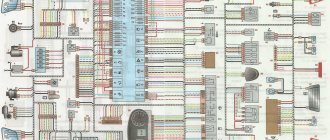
Electrical diagram of VAZ-21213
1. Headlights 2. Side turn signals 3. Windshield washer motor 4. Headlight washer motor *. 5. Switch 6. Battery 7. Starter VAZ-21213.8. Generator 9. Headlights 10. Headlight washer gear motors *. 11. Horn 12. Spark plugs 13. Carburetor limit switch 14. Carburetor solenoid valve 15. Ignition coil 16. Windshield wiper motor 17. Carburetor solenoid valve control unit 18. Ignition distributor 19. Coolant temperature sensor 20. Oil pressure indicator sensor 21 .Portable flashlight ** 22. Insufficient brake fluid level indicator sensor 23. Windshield wiper relay 24. Rear fog lamp activation relay *** 25. Rear window heating element activation relay. 26. Relay for turning on headlight washers and washers *. 27. Low beam relay 28. High beam relay 30. Starter relay 31. Hazard and turn signal switch relay 32. Electric heater motor 33. Additional resistance of the electric heater motor 34. Lighting indicators for the heater control levers 35. Exterior light switch. 36. Main fuse box 37. Additional fuse box 38. Reversing light switch 39. Brake light switch 40. Instrument lighting control 41. Ignition switch 42. Three-lever switch 43. Alarm power switch 44. Headlight and headlight washer switch 45. Switch heater electric motor 46. Rear window resistance switch 47. Rear fog light switch 48. Light switches are located in the door shelves 49. Interior lamps 50. Cigarette lighter VAZ-21213.51. Carburetor choke warning lamp switch 52. Carburetor choke warning lamp 53. Differential lock warning lamp switch 54. Parking brake warning lamp switch 55. Fuel level and reserve sensor 56. Instrument cluster 57. Rear windshield washer motor 58. Tail lights 59 Block for connecting additional brake lights 60. Blocks for connecting side sensors 61. Blocks for connecting to the rear window heater 62. License plate lights 63. Rear window wiper motor.
The order of conditional numbering in blocks: A - windshield wipers for headlights and rear window, windshield wiper relay switch; B — ignition distributor sensor; B - signal relay switch and turn signals; G - switch; D - three-lever switch; E - hazard warning switch; W — relay for turning on rear fog lights; Z — rear lights; E - instrument cluster VAZ-21213.
In the dashboard wiring, the second ends of the white wires are brought together into one point, which is connected to the dimmer of the device. The other ends of the black wires are also connected at a point connected to ground. The other ends of the yellow wires with the blue stripe connect at a point connected to the "A" terminal of the main fuse box. And the second ends of the orange wires are also connected at the point connected to the "B" terminal of the main fuse box.