Causes of malfunction
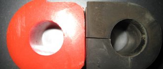
View of the old and new voltage regulator relay
There are several reasons for the failure of the regulator relay on a car. Let's consider the main ones :
- A short circuit in the on-board network, which led to the failure of the regulator relay. This happens quite often because the generator itself serves as the power source and there is no fuse between it and the current produced to protect it.
- Wear . Like any part in a car, the regulator relay can wear out.
- The brushes are worn out .
The arrow indicates worn brushes. Their length is 3 mm instead of the required 5 mm.
How to determine that the regulator relay has failed?
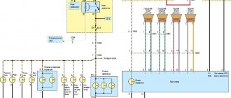
Connection diagram of the generator to the electrical circuit
Let's consider the main options:
- Insufficient battery charge means that after the ignition is turned off, the car has difficulty starting or may not start at all.
- The light shines normally at 2000 rpm, but dims at idle.
Once the root causes have been sorted out, you can move on to the replacement process.
Kalina generator design
The process of replacing the generator regulator relay
So, the process of replacing the generator regulator relay will require dismantling the product itself, but it will not require a pit, and all operations can be carried out from the engine compartment. Let's take a step-by-step look at how to replace the generator regulator relay on a Lada Kalina:
- We remove the “minus terminal”.
- To replace the relay, you will have to dismantle the generator.
The device serves to transform mechanical energy from the crankshaft into electricity. The generator charges the battery and is also a source of alternating current and power for all electrical equipment of the car. It has a diode bridge (rectifiers) and a voltage regulation unit, operating in parallel with the battery.
Recommendations for increasing the service life of the regulator
In order to increase the service life of the voltage regulator, it is necessary to adhere to several simple rules aimed at implementing preventive measures. Among them:
- do not allow excessive contamination of the generator, periodically inspect its condition, and, if necessary, dismantle and clean the unit;
- check the tension of the alternator belt, tighten it if necessary (either yourself or in a car service);
- monitor the condition of the generator windings, in particular, do not allow them to darken;
- check the contact on the control wire of the relay-regulator, both its quality and the presence of oxidation on it;
- Perform periodic voltage checks on the vehicle battery with the engine running.
Following these simple rules will allow you to increase the resource and service life of both the generator and the vehicle voltage regulator.
Results
Checking the voltage regulator relay is not a difficult task, and almost any car enthusiast with basic repair skills can handle it. The main thing is to have the appropriate tools for this - a multimeter, a power supply with a voltage regulator (although you can connect it to a battery with a charger), a 12 V lamp and pieces of wires for mounting the appropriate circuit.
If during the inspection you find out that the regulator is out of order, then it must be replaced (repair work is usually not carried out). The main thing is not to make a mistake when choosing it and purchase the part that is suitable specifically for your car.
| Home Auto Electronics Voltage regulators for automobile alternators |
Rice. 1. Methods of controlling the excitation current: G - generator with parallel excitation; Wв — excitation winding; Rd - additional resistance; R - ballast resistance; K - current switch (regulating body) in the excitation circuit; a, b, c, d, e are indicated in the text.
A modern automobile internal combustion engine (ICE) operates over a wide speed range (900–6500 rpm). Accordingly, the rotor speed of the automobile generator changes, and therefore its output voltage.
Standard generator Grants
At the factory, VAZ 2190 and 2191 are equipped with a device with the catalog designation KZATE 115A (9402.3701-14). It has the following technical characteristics:
- rated voltage – 14 V;
- maximum current – 115 A;
- shaft rotation speed – 1200 rpm. (without load);
- shaft rotation speed at a maximum current of 115 A – 6000 rpm.
The main components of the generator are a stationary stator and a rotor rotating in it. The parts are separated from each other by an air gap. Their main working part is the winding and magnetic circuit. Other components serve to provide adequate rigidity, cooling, etc.
The brush assembly is necessary to connect the rotor electrical network to the stationary stator winding; it consists of several graphite contacts. A diode bridge is used to convert AC to DC current and is also called a rectifier block. The regulator converts the output electricity into the desired voltage.
Changing the generator regulator relay on Lada Kalina
A three-phase voltage regulator (charging relay) is installed on the generator. Responsible for maintaining the voltage of the on-board network within a given limit in all operating modes.
The output voltage may be affected by changes in rotor speed, electrical load, and ambient temperature.
Failure is considered one of the most common problems associated with the operation of the generator. Replacing an element does not require practical skills.
Replacement process
The process of removing the generator on Kalina depends on whether it has a tensioner on it or not. A belt without a tensioner can only be removed together with the generator or simply cut (if it’s old).
- Disconnect the negative wire from the battery.
- Loosen the generator and remove the belt.
Use a 13 key to loosen the tensioner and remove the belt.
By pressing the latch, we snap off the plastic block.
Lift the boot and unscrew the nut by 10.
The mounting bolts are located at the top and bottom of the generator.
The latches are located on the side surface of the cover.
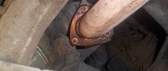
Mounting the regulator relay: 1 – contact under the bushing, 2 – bolts securing the relay body.
View of the generator with the relay removed.
After assembling the unit, it is necessary to check the reliability of the wire connections and tighten the generator belt.
Important! Before installing a new generator charging relay on Kalina, it is recommended to check its condition: make sure that the brushes are intact (they must protrude from the relay housing by at least 5 mm ); easy, without delay, clicking into the initial position after pressing.
Critical wear of the brushes on the old relay.
Briefly about articles and applicability
We should talk about the applicability of a particular charging relay after the model of the generator from which it was removed has been installed.
9402.3701-06 or 9402.3701-14 ( 14 V , 85 A were predominantly installed on Kalina, Granta and Priora . Part numbers of compatible voltage relays:
- KZATE "Orbita" (Saransk) 849.3702 , costing 500-750 rubles .
New voltage regulator made in Saransk.
Important ! On Priors with a generator 3701010 , which has an output current of up to 115 A, is not interchangeable with the Kalinovsky one !
Causes and symptoms of malfunction
The regulator will need to be replaced if the part fails. This can happen for several reasons:
- Short circuit in the circuit , which led to its breakdown. This happens quite often, since the “relay” is a power source, and there is no fuse between it and the rotor.
- Brushing of brushes resulting from friction against the rotor .
You can find out about problems with the operation of the generator, in particular with the charging relay, by changing the voltage of the on-board network.
In practice, during the operation of the car this is determined by the following symptoms:
- Headlight beams of different brightness . When you press the gas pedal they light up brighter, at idle they dim.
- An undercharged battery will affect the morning start-up. The starter turns much harder than usual.
Battery overcharging due to increased voltage . It can affect you in several ways:
- Electrolyte boiling in jars . It will manifest itself as a sharp, unpleasant odor emanating from the battery;
- Frequently blown fuses . If they are missing, the “weakest” part of the wiring will burn out (places with pockets of copper oxidation, poor contacts).
Basic faults
Failures associated with the failure of the Granta generator lead to discharge or, conversely, overcharging of the battery and its boiling. In both cases, this will make further operation of the car impossible. If the belt is overtightened, problems with high bearing wear will soon arise. If the belt tension is insufficient, slipping will occur and the battery will receive too little charge.
Normally, a working generator produces 14.5 V; exceeding this value is most often due to a breakdown of the voltage regulator. Without urgent replacement of the element, constant recharging of the battery will lead to shedding of lead plates and battery malfunction. If the unit does not produce the required voltage, and it is below 13 V, then the problem may not only be with the regulator, but also with the fact that the brushes are worn out, the diode bridge or windings are damaged.
It happens that suspicious sounds occur during operation, in which case the nature of the noise is important. It’s not difficult to deal with this: just remove the wires from the generator. If the rotation of the pulley is accompanied by a howling or squealing noise, then the problem is in the bearings. If, after removing the wires, the noise disappears, then it is in the diode bridge, or a short circuit has occurred in the winding. In any case, repairs are inevitable, and sometimes only replacing the unit will help.
Typical faults and methods for their elimination:
Cause of malfunction
Remedy
The table shows the main faults. Mechanical and other damage is also possible.
Generator brushes.
Generator brushes are a part that is found in almost every generator.
The more modern the car, especially a foreign car, the more electrical consumers it has, which in one way or another make life easier for the car owner. Accordingly, an increasingly important role among automobile units is played by the autogenerator, which supplies electricity to all consumers in the car.
What are generator brushes used for?
Using the generator brushes, the voltage from the regulator relay is supplied to the excitation winding - the rotor. The rotor has commutator rings attached to it - the rotor commutator to which the brushes fit tightly. To transfer current from the voltage relay to the rotor winding, the brushes must be in a certain position and pressed against the commutator rings with a certain force. To do this, they are installed in the seats of the brush holder and are pressed by a spring on the reverse side.
The material from which the brushes of foreign manufacturers' generators are made - a mixture of copper and graphite - differs from domestic ones in better wear resistance and conductivity. For this reason, it is not recommended to install this element on foreign cars from domestic cars.
How do you know when you need to replace your generator brushes?
- Car mileage, 150-200 thousand km. is the period when the part is worn out.
- The battery charging indicator light comes on and goes off again. This may continue for several days until the icon lights up completely.
- Loss of power or voltage drop due to a loose fit of a worn part.
- Voltage surges in the vehicle's on-board network may indicate a faulty part.
- If a lot of motor oil or other technical fluid gets on the generator, then the part is subject to increased wear.
How to check whether replacing the generator brushes is really necessary?
To determine the causes of the malfunction, it is necessary to disassemble the generator and inspect the generator brushes - they must be long enough and in contact with the slip rings.
If the remaining length of at least one element is less than 3 mm, replacement is necessary in any case. Also, the generator brushes must be well movable in their seats, have approximately equal residual length, must not be dirty, and the springs must press with the same force.
How to replace brushes on a generator? Procedure.
On many modern autogenerators, the brushes are integral with the voltage regulator relay, for example, this is true for Valeo, Bosch, Mitsubishi, Magneti Marelli; for Denso, the relay regulator is made separately from the brush assembly.
To replace the generator brushes , if they are built into the regulator relay, the tools you will need are a 40-100 W soldering iron, solder, flux, a 1.5-3 mm drill, a drill or screwdriver, as well as a tool for removing the regulator.
Alternative belt replacement options
Insufficient tension creates less inconvenience than constriction. The latter provokes too rapid wear of the bearings. To avoid such a problem, many Grant owners install the tensioner themselves: a part from the Lada Kalina is perfect for this.
The manufacturer does not initially install the part at the factory, since it positions Granta as the most affordable in its class, hence the savings on components. This is typical for the cheapest models with an 8-valve power unit.
To adjust the belt tension, you can use a bracket from Kalina, modifying it a little with your own hands. To do this you will need the following set:
- bracket;
- tensioner;
- roller bracket;
- alternator belt from Kalina 1;
- screw tensioner.
Thanks to this kit, you can significantly improve the design of your car, extending the service life of some parts and components.
Checking and replacing the voltage regulator on the Lada Granta generator
Tools:
- Open-end wrench 8 mm
- Open-end wrench 10 mm
- Open-end wrench 12 mm
- Open-end wrench 13 mm
- Open-end wrench 19 mm
- Ratchet wrench
- 8 mm head
- 13 mm head
- Medium flathead screwdriver
- Large flat-head screwdriver (for alternator without tensioner)
- Knife (for generator without tensioner)
- Vernier calipers (or ruler)
- Test instrument with ohmmeter and voltmeter functions
- Torque wrench
Parts and consumables:
- Battery (or 12V power supply)
- Connecting wires with terminals
- Indicator lamp 12 V
- Voltage regulator (replacement if necessary)
Notes:
Initially, check the voltage regulator without removing the generator from the car. For this:
1. Move the rubber boot aside and connect the plus wire to the volts, and the minus wire to the generator housing.
2. Start the engine and turn on the car's headlights.
3. After 15 minutes of engine operation at medium speed, measure the voltage; it should be 14.4-15.1 V. If an incomplete charge or overcharge is observed (the voltage does not fall within the specified limits), replace the voltage regulator on the generator.
1. Disconnect the negative battery terminal.
2. Remove the alternator from the vehicle as indicated here.
3. Remove the brush holder from the alternator voltage regulator relay assembly as described here.
4. Check the ease of movement of the brushes in the brush holder and their protrusion.
Note:
If the brushes protrude less than 5 mm from the brush holder, replace the voltage regulator with brush holder.
5. Check that the voltage regulator is working properly. Connect a 12V test lamp to the brushes. Apply a voltage of 12 V “plus” to the terminal, and minus to the “ground” of the brush holder. In this case, the control lamp should light up.
Note:
Set the voltage to 15-16 V. The lamp should go out. If the lamp is on or off in both cases, then the regulator with brush holder is faulty and needs to be replaced.
6. Install a new voltage regulator (if necessary), assemble the generator and install in the reverse order of removal.
Note:
If necessary, you can check and replace the voltage regulator without removing the generator from the car.
The article is missing:
- Photo of the instrument
- Photos of parts and consumables
Generator replacement
The problem with the standard Lada Granta generator is known to many owners of this car. To troubleshoot problems, it is most often necessary to remove the device. Conventionally, unit breakdowns can be divided into two types - mechanical and electrical. But one of the most common problems associated with replacing a device is the natural wear and tear of components. Therefore, sooner or later, every car enthusiast faces the question of replacing or repairing a generator.
The procedure has some difficulties, but it is quite possible to do it yourself. Removing the unit may also be necessary for maintenance or to improve the design of the car. The dismantling procedure has its own characteristics depending on the engine configuration (8- or 16-valve), as well as on the presence of air conditioning.
Replacing the Grant Voltage Regulator
Checking and replacing the Lada Granta voltage regulator
To make sure that the voltage regulator is working properly, turn off all consumers except the high beam headlights and measure the voltage at the battery terminals.
It should be in the range of 14.4 - 15.1 V, at an engine speed of 3000 min -1.
If the voltage differs from the specified one, the regulator must be replaced.
You can remove the brush holder with the regulator without removing the generator from the car.
1. Disconnect the wire terminal from the negative terminal of the battery.
2. Disconnect the wiring harness block from the generator.
3. Remove the protective rubber cover...
...and use a 13 mm socket wrench to unscrew the nut securing the wire lugs to the “B+” terminal of the generator.
4. Remove the ends of the two wires from the contact bolt.
5. Release the three spring clamps securing the casing of the rectifier unit (shown on the removed generator) and remove the casing from the generator.
6. Disconnect the voltage regulator wire block from the output of the rectifier unit
7. Using an 8 mm socket wrench, unscrew the two bolts securing the voltage regulator
8. Using a 12 mm open-end wrench, unscrew the contact bolt nut
9. Disconnect the lead from the contact bolt and remove the voltage regulator
We install the voltage regulator in the reverse order of removal.
Before installing a voltage regulator that is in operation, we inspect the brushes and make sure they are mobile.
If the brushes are broken or badly worn (protrude no more than 5 mm from the brush holder), or they become wedged in the brush holder, the regulator must be replaced.
Replacing a generator on an 8-valve Granta engine
To work, you need to use three keys (at “8”, “10”, “13”) and a mounting blade. First, disconnect the “–” terminal from the battery. The operating procedure is as follows:
- Remove the engine protection by removing two rear and four front bolts.
- Disconnect the wire block.
- Remove the protective cap from the nut that holds the power wire.
- Unscrew the power cable nut.
- Release the top fastening by unscrewing the nut.
- Move the generator away with a mounting spatula or a long screwdriver, and remove the upper mounting bolt.
- Loosen the lower fastening.
- Press the generator from the engine using improvised means, for example, a mounting spatula, removing the lower mounting bolt.
- Move the generator to the right side.
- Remove the belt from the pulleys.
- Remove the generator.
To install the device in its original place, perform all steps in reverse order. You need to make sure that the grooves on the pulleys match the grooves on the belt.
Checking and replacing the Lada Granta voltage regulator
To make sure that the voltage regulator is working properly, turn off all consumers except the high beam headlights and measure the voltage at the battery terminals.
It should be in the range of 14.4 - 15.1 V, at an engine speed of 3000 min -1.
If the voltage differs from the specified one, the regulator must be replaced.
You can remove the brush holder with the regulator without removing the generator from the car.
1. Disconnect the wire terminal from the negative terminal of the battery.
2. Disconnect the wiring harness block from the generator.
3. Remove the protective rubber cover...
...and use a 13 mm socket wrench to unscrew the nut securing the wire lugs to the “B+” terminal of the generator.
4. Remove the ends of the two wires from the contact bolt.
5. Release the three spring clamps securing the casing of the rectifier unit (shown on the removed generator) and remove the casing from the generator.
6. Disconnect the voltage regulator wire block from the output of the rectifier unit
7. Using an 8 mm socket wrench, unscrew the two bolts securing the voltage regulator
8. Using a 12 mm open-end wrench, unscrew the contact bolt nut
9. Disconnect the lead from the contact bolt and remove the voltage regulator
We install the voltage regulator in the reverse order of removal.
Before installing a voltage regulator that is in operation, we inspect the brushes and make sure they are mobile.
If the brushes are broken or badly worn (protrude no more than 5 mm from the brush holder), or they become wedged in the brush holder, the regulator must be replaced.
Replacing a generator on a car with a 16-valve engine
Dismantling and subsequent installation of the device on Grant modifications with a 16-valve power unit have their own characteristics: there is a belt tensioner. Therefore, the procedure for removal and installation is somewhat more complicated. As in the previous case, you will need a standard set of tools, and before starting work, the negative terminal of the battery is disconnected. It is necessary to remove the engine protection, if any. After this, you can begin to remove the unit by following these steps:
- Disconnect the wiring harness from the generator.
- Remove the cap covering the power wire.
- Using a “10” wrench, unscrew the nut that holds the wire tip.
- Use a key set to “13” to loosen the tension bar nut.
- Loosen the belt by unscrewing the adjusting bolt to the left.
- Move the generator to the right and remove the belt.
- Unscrew the adjustment bolt completely and remove it.
- Remove the tension bar.
- Unscrew the fastening nut from below.
- Remove the bushing and remove the bolt holding the lower mount.
- Remove the generator.
To install, do all the steps starting from the end, then tighten the belt.
How to replace the voltage regulator and check its serviceability on a VAZ 1117-VAZ 1119?
Checking the voltage regulator for serviceability:
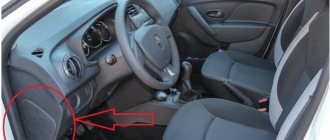
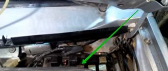
1) At the beginning of the operation, you will need to find where the generator itself is located and after you find it, move your hand to the side with the rubber cover indicated by the red arrow, this cover covers the “B+” terminal; in simpler words, this is the positive terminal and it comes from the generator to this terminal (By the way, it is also indicated by a blue arrow) you will need to connect the positive wire of the voltmeter and after connecting it, throw another wire (Minus wire) coming from the same voltmeter to ground (The places where you need to connect the wire , indicated by a green arrow), after the operation has been completed, a DC voltmeter will show you the voltage in the vehicle’s on-board network.
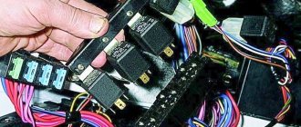
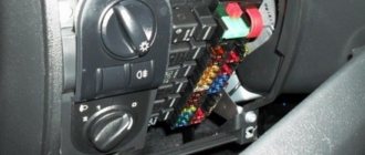
Block in the cabin
On cars of all years of production, it is located near the driver’s left foot and is covered with a plastic panel.
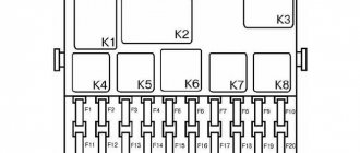
Appearance
The diagrams and their explanation are given below. The LADA Granta cigarette lighter fuse is designated as follows:
- 2011-2014 in: F20;
- 2015: F18;
- 2016, 2022: F27;
- 2018 - present v.: F25
For cars assembled in 2011-2014
Circuit breakers
| Designation | Denomination, A | Protected element |
| F1 | 15 | Controller; Cooling fan; Ignition coil; Injectors |
| F2 | 30 | Power window motors |
| F3 | 15 | Alarm |
| F4 | 20 | Windshield wiper, airbags |
| F5 | 7.5 | Ignition switch (pin 15) |
| F6 | 7.5 | Reversing lamp in the right rear lamp |
| F7 | 7.5 | Canister purge valve; Sensors: mass air flow, vehicle speed, oxygen concentration |
| F8 | 25 | Rear window heating element |
| F9 | 5 | Side lights (right side) |
| F10 | 5 | Side lights (left side); Illumination of the instrument cluster and switches on the instrument panel |
| F11 | 5 | Fog lamp in the left rear light |
| F12 | 7.5 | Low beam headlights, right headlight |
| F13 | 7.5 | Low beam headlights, left headlight |
| F14 | 10 | High beam headlights, right headlight |
| F15 | 10 | High beam headlights, left headlight |
| F16 | – | Not used (until 2013) |
| 10 | PTF right (since 2013) | |
| F17 | – | Not used (until 2013) |
| 10 | PTF left (since 2013) | |
| F18 | – | Not used (until 2013) |
| 15 | Heated seats (since 2013) | |
| F19 | – | Not used (until 2013) |
| 10 | ABS/ESC | |
| F20 | 15 | Sound signal; Instrument cluster; Cigarette lighter; Diagnostic connector; Electric trunk lock |
| F21 | 15 | Fuel pump |
| F22 | 15 | central locking |
| F23 | 10 | Daytime Running Lights |
| F24 | – | Not used (reserve) |
| F25 | 10 | Main and additional brake lights; Interior lighting |
| F26 | – | Not used (reserve) |
| F27 - F30 | – | Spare fuse |
| F31 | – | Not used (reserve) |
| F32 | 30 | Heater fan motor and electric power steering control circuits |
Relay
| Designation | Protected element |
| K1 | Cooling fan motor |
| K2 | Power window motors |
| K3 | Starter |
| K4 | Low and high beam headlights; Daytime Running Lights; Heated rear window; Heater fan motor; Windshield cleaner and washer |
| K5 | Turn signal lamps |
| K6 | Windshield wiper motor |
| K7 | High beam headlights |
| K8 | Sound signal |
| K9 | dipped headlights |
| K10 | Heated rear window |
| K11 | Engine ECU |
| K12 | Fuel pump |
For cars assembled in 2015
In 2015, there were 2 versions of the interior fuse box in the LADA Granta: from ABAR and Delphi. Their diagrams and explanations are given below.
AVAR block diagram
Delphi block diagram
Circuit breakers
| Designation | Denomination, A | Protected Circuits |
| F1 | 15 | Ignition coils; Injectors; Engine Control System Controller |
| F2 | 5(1) | Daytime Running Lights |
| 25(2) | Central body electronics unit; Driver door module | |
| F3 | 10(1) | Alarm |
| 10(2) | Automatic transmission control controller; Automatic gearbox control drive | |
| F4 | 10 | Airbag system controller |
| F5 | 7.5 | Terminal 15 devices |
| F6 | 7.5(1) | Reversing light; Direction indicators |
| 7,5(2) | Reversing light; Automatic transmission control controller; Safe parking system control unit | |
| F7 | 7.5 | Canister purge valve; Sensors: mass air flow/pressure, phases, oxygen concentration |
| F8 | 25 | Heated rear window(1) Heated rear window and outside mirrors(2) |
| F9 | 5 | Side lights (right side) |
| F10 | 5 | Side lights (left side); Illumination of instruments and keys; License plate lights; Luggage and glove box lighting |
| F11 | 5 | Rear fog lights |
| F12 | 10 | Low beam (right headlight); Electrical corrector for right headlight |
| F13 | 10 | Low beam (left headlight); Left headlight electric corrector |
| F14 | 10 | High beam (right headlight) |
| F15 | 10 | High beam (left headlight) |
| F16 | 10 | Fog lights, right(2) |
| F17 | 10 | Fog lights, left(2) |
| F18 | 20 | Front seat heaters; Cigarette lighter |
| F19 | 15 | Door locking motors(1) |
| 5 | ABS(2) | |
| F20 | 15 | Sound signal |
| F21 | 10 | Fuel pump |
| F22 | 15(1) | Washers, windshield and rear window cleaners; |
| 25(2) | Central body electronics unit; | |
| F22 | 25(2) | Central body electronics unit; Washer, rear window cleaner |
| F23 | 5 | Instrument cluster; Diagnostic connector |
| F24 | 7.5(2) | Air conditioning compressor clutch; Automatic climate control system controller |
| F25 | 7.5(1) | Brake signals; Interior lighting |
| 7,5(2) | Brake signals | |
| F26 | 10(2) | Central body electronics unit |
| F31 (for the pre-function block AVAR) F27 (for the pre-function block Delphi) | 30 | Power windows for front doors(1) |
| 25 | ABS(2) | |
| F32 (for the pre-function block AVAR) F28 (for the pre-function block Delphi) | 30(1) | Electric heater fan |
| 30(2) | Electric heater fan; Automatic climate control system controller |
Relay
| Designation | Protected Circuits |
| K1 | Electric radiator cooling fans |
| K2 | Power windows(1) Electric radiator cooling fans(2) |
| K3 | Additional starter relay |
| K4 | Ignition switch unloading relay |
| K5 | Turn signals and hazard warning lights(1) |
| K6 | Windshield wiper(1) Heated seats(2) |
| K7 | High beam headlights |
| K8 | Sound signal |
| K9 | dipped headlights |
| K10 | Heated rear window; Heated exterior mirrors(2) |
| K11 | Engine ECU |
| K12 | Fuel pump |
| K13 | Additional hazard warning lights(1) Reversing lights(2) |
| K14 | Additional hazard warning lights(1) Electric radiator cooling fans(2) |
| K15 | Heated windshield(2) |
| K16 | |
| K17 | A/C electromagnetic clutch(2) |
Note to the table:
- (1): “Standard” package;
- (2): “Norma”, “Lux” configurations.
For cars assembled in 2016, 2022
Circuit breakers
| Designation | Denomination, A | Protected Circuits |
| F1 | 15 | Ignition coils; Injectors; Engine Control System Controller |
| F2 | 30 | Central body electronics unit(3) |
| F3 | 15(1),(2) | Alarm |
| 10(3) | Central body electronics unit; Light switch | |
| F4 | 20(1),(2) | Windshield washer and wiper |
| 15(3) | Airbags; Rain sensor | |
| F5 | 7.5 | Terminal 15 devices |
| F6 | 7.5(1),(2) | Reversing light; Direction indicators |
| 7.5(3) | Reversing light; Safe parking system | |
| F7 | 7.5 | Canister purge valve; Sensors: mass air flow/pressure, phases, oxygen concentration; Tire pressure monitoring system(2),(3) |
| F8 | – | Reserve |
| F9 | 5 | Side lights (right side) |
| F10 | 5 | Side lights (left side); Illumination of instruments and keys; License plate lights; Trunk lighting; Glove compartment lighting(2),(3) |
| F11 | 5 | Rear fog lights |
| F12 | 10 | Low beam headlights (right headlight) |
| F13 | 10 | Low beam headlights (left headlight) |
| F14 | 15 | Cartridge for connecting additional devices in the trunk |
| F15 | 10 | Rear window wiper and washer (optional) |
| F16 | 5 | Driver door module(3) |
| F17-F20 | – | Reserve |
| F21 | 10 | High beam headlights (left headlight) |
| F22 | 10 | High beam headlights (right headlight) |
| F23 | 10 | Fog lamp (right) |
| F24 | 10 | Fog lamp (left) |
| F25 | 15 | Heated front seats(2),(3) |
| F26 | 5 | ABS/ECS |
| F27 | 15 | Cigarette lighter |
| F28 | 15 | Fuel pump |
| F29 | 15 | Motor gearboxes for locking doors and trunk(1),(2) |
| 20 | Central body electronics unit; windshield cleaner and washer(3) | |
| F30 | 10 | Daytime running lights(1),(2) |
| F31 | 7.5 | A/C compressor clutch(2),(3) |
| F32 | 7.5 | Brake signal; Automatic transmission control controller(2),(3); Interior lighting(1),(2) |
| F33 | 25 | ABS/ECS |
| F34 | 5 | Instrument cluster; Diagnostic connector |
| F35 | 15 | Airbags(1),(2) |
| F36 | 10 | Sound signal |
| F37 | 10 | Multimedia system |
| F38-F40 | – | Reserve |
| F41 | 50 | Heated windshield(2),(3) |
| F42 | 30 | Power windows for front doors(2) |
| F43 | 50 | Robotic gearbox control controller |
| F44 | 30 | Electric heater fan; Air conditioning control system controller(2),(3) |
| F45 | 25 | Heated rear window Heated outside mirrors(2),(3) |
| F46 | – | Reserve |
Relay
| Designation | Protected Circuits |
| K1 | Ignition switch unloading relay |
| K2 | Starter |
| K3 | Windshield wiper(1),(2); Radiator cooling fan(3) |
| K4 | Electric radiator cooling fan; Turn signals and hazard warning lights(1),(2) |
| K5 | A/C compressor clutch(3) |
| K6 | Front power windows(2) Heated rear window and outside mirrors(3) |
| K7 | High beam headlights |
| K8 | Sound signal |
| K9 | dipped headlights |
| K10 | Reversing light(2),(3) |
| K11 | Engine ECU |
| K12 | Fuel pump |
| K13 | Heated seats(2),(3) |
| K14 | Heated windshield(2),(3) |
| K15 | Heated rear window and exterior mirrors(1),(2) |
| K16 | A/C compressor clutch(2) |
| K17 | Reserve |
| K18 | Radiator cooling fan(2) |
Note on tables:
- (1): “Standard” package;
- (2): “Norma” package;
- (3): “Lux” package.
For cars assembled from 2022
Circuit breakers
| Designation | Denomination, A | Protected element |
| F1 | 15 | Electric radiator fan (minimum speed) (version with air conditioning or climate control system); Electric radiator fan (maximum speed); Air conditioning compressor clutch (cars with air conditioning or climate control); Engine ECU; Injectors; Ignition coils 2×2 (for 8-valve internal combustion engines); Ignition coils (for 16-valve internal combustion engines) |
| F2 | 7.5 | Intake pipe damper valve (for engine 21127); Canister purge valve; Oxygen, phase sensors (for 16-valve engines), mass air flow (for 8-valve internal combustion engines or 16-valve engines 21126); AMT selector (version with AMT controller); Tire pressure monitoring system |
| F3 | 5 | ABS/ECS |
| F4 | 15 | Airbags |
| F5 | 7.5 | Automatic Transmission Starter/Controller; Ignition switch unloading relay; Heated windshield and rear window; Seat heating; Fuel pump; ECU for electrically heated windshield; Engine ECU; Audio system; Electric power steering ECU; Wiper switch; Central body electronics unit; Terminal block "ERA-GLONASS"; Clutch pedal switch (for manual transmission); Brake pedal switch; Instrument cluster; Door lock system; Driver's door lock switch; Air conditioner switch; Automatic transmission speed sensor; Automatic transmission mode switch; AMT controller; Tire pressure monitoring system |
| F6 | 7.5 | Reversing light; Direction indicators; Parking system ECU |
| F7 | 10 | High beam (right) |
| F8 | 10 | High beam (left |
| F9 | 5 | Side lights (right side) |
| F10 | 5 | Side lights (left side); License plate lights; Trunk light; Illumination of instruments and keys |
| F11 | 5 | Rear fog lights |
| F12 | 10 | Low beam (right); Electric headlight corrector |
| F13 | 10 | Low beam (left); Electric headlight corrector |
| F14 | 20A | Central body electronics unit; Cleaner, windshield washer; Steering column wiper switch |
| F15 | 10 | Cleaner, rear window washer |
| F16 | 5 | Audio system; Ignition switch unloading relay |
| F17 | 5 | Door lock system |
| F18 | 5 | Heated mirrors |
| F19, F20 | – | Reserve |
| F21 | 15 | Fuel pump |
| F22 | 7.5 | Brake light switch |
| F22 | 7.5 | Main and additional brake lights; ABS/ECS; AMT controller |
| F23 | 5 | Instrument cluster; Diagnostic connector |
| F24 | 10 | Sound signal |
| F25 | 15 | Cartridge for connecting additional consumers in the passenger compartment/Cigarette lighter |
| F26 | 5 | Terminal block "ERA-GLONASS" |
| F27 | 10 | Fog lamp (right) |
| F28 | 10 | Fog lamp (left) |
| F29 | 15 | Heated front seats |
| F30 | 10 | Audio system |
| F31 | 10 | Direction indicators; Power supply for body electronics unit; Daytime Running Lights |
| F32 | 30 | Central body electronics unit: electric windows; Door and trunk locks; Rain sensor; Interior, glove box and trunk lighting |
| F33 | 5 | Driver door module |
| F34 | 7.5 | Air conditioning compressor clutch (version with air conditioning or climate control system); Automatic climate control system controller |
| F35 | 15 | Automatic transmission controller; Automatic transmission control drive |
| F36 | 15 | Alarm |
| F37 | 15 | Trunk lock actuator switch; Trunk lock actuator control relay; Trunk lighting; Door lock control unit |
| 5 | Trunk lock actuator switch; Trunk lighting | |
| 25 | Trunk lock actuator switch; Trunk lock actuator control relay; Trunk lighting; Door lock control unit | |
| F38 | 10 | Daytime Running Lights |
| F39 | 15 | Cartridge for connecting additional consumers in the trunk |
| F40 | 10 | Trailer |
| F41 | 50 | Heated windshield |
| F42 | 30 | Heated rear window and exterior mirrors |
| F43 | 50 | AMT controller |
| F44 | 30 | Electric heater fan; Automatic climate control system controller |
| F45 | 30 | Power windows for front doors; Exterior mirror control |
| F46 | – | Reserve |
Relay
| No. on the diagram | Denomination, A | Purpose |
| K1 | 50A | Ignition switch unloading relay |
| K2 | 30A | Starter |
| K3 | 30A | Windshield wiper; Autostart (optional) |
| K4 | 30A | Electric radiator fan of maximum speed (optional) |
| K5 | 30A | Turns and hazard warning lights; K15A (autostart) (in variant version) |
| K6 | 30A | Heated rear window |
| K7 | 20A | High beam headlights |
| K8 | 20A | Sound signal |
| K9 | 20A | dipped headlights |
| K10 | 20A | Air conditioning compressor clutch (version with air conditioning or climate control) |
| K11 | 20A | ECM main relay |
| K12 | 20A | Fuel pump |
| K13 | 20A | Heated seats (optional) |
| K14 | 70A | Heated windshield (optional) |
| K15 | 20A | Turning on the alarm |
| K16 | 30A | Alarm power supply; Turning on the reverse lamp (optional) |
| K17 | 30A | Electric windows; Radiator fan in autostart mode (optional) |
| K18 | 30A | Minimum speed radiator fan (optional) |